adding oil PONTIAC FIERO 1988 Service Repair Manual
[x] Cancel search | Manufacturer: PONTIAC, Model Year: 1988, Model line: FIERO, Model: PONTIAC FIERO 1988Pages: 1825, PDF Size: 99.44 MB
Page 44 of 1825
AIR CONDITIONING 1B-1
SECTION 1B
R COND
When performing air conditioning diagnosis on vehicles equipped with a catalytic converter, it will be necessary to
WARM the engine to a NORMAL operating temperature BEFORE attempting to idle the engine for periods greater
than five
(5) minutes. Once the engine attains normal idle, diagnosis and adjustments can be made.
CONTENTS
.................. General Description .................................. 1B-1 Accumulator Assembly Service .1B-19
.......................... C.C.O.T. A!C System ................................ 1B-1 On-Vehicle Sewice ..... 1B-20
....................................... System Components - Functional ................. 1B-2 Blower Motor .1B-20
..................................... System Components - Control ..................... 1B-3 Hi-Blower Relay 1B-20
...................................... Relays and Switches ................................... 1B-3 Blower Resistor 1B-20
Diagnosis ................................................. 1B-5 Controller, Blower Switch or Vacuum
................................................ Testing the Refrigerant System ...................... 1B-5 Valve .lB-20
Insufficient Cooling "Quick-Check Temperature Control Cable ....................... .1B-20
.................................... Procedure.. ............................................. 1B-5 Vacuum
Harness .lB-20
C.C.O.T. A/C System Diagnostic Control Wiring Harness ........................... .1B-20
..... ................................. Procedure.. ............................................. 1B-8 Heater
Core .. .lB-21
................................ Leak Testing ........................................... 1B-12 Lower Heater Outlet 1B-21
............................... Service Procedures ................................. .1B-12 Heater Module Case .lB-21
.......................... O-Ring Replacement ................................ .1B- 12 Pressure Cycling Switch .1B-21
....................................... Handling Refrigerant- 12 ............................ .1B- 13 Vacuum Tank .lB-21
Discharging, Adding Oil, Evacuating Liquid Line .......................................... .1B-23
and
Charging Procedures - AIC Accumulator ......................................... .1B-23
.................................... Systems .............................................. .1B-14 Evaporator Core .1B-24
In-Line Air Conditioning Evaporator Case .................................... .1B-24
.......................................... Filter
Installation.. .................................. .1B- 18 Compressor .lB-24
.............................................
................ Expansion Tube (Orifice) Service .1 B- 19 Condenser IB-24
GENERAL DESCRIPTION
All engines are equipped with a fixed displace- evaporator temperature. The pressure cycling switch
ment (R-4) air conditioning compressor. This
com- is the freeze protection device in the system and
pressor may cycle on and off under normal air
senses refrigerant pressure on the suction side of the
conditioning demand. system. This switch is located on a standard
Schrader- -
All air conditioning systems that use the fixed
displacement R-4 compressor are referred to as
C. C.O.T. (Cycling Clutch, Orifice Tube) type sys-
tems. This is the same system that has been used on
all General Motors vehicles in the past several years.
The C.C.O.T. NG System
The Cycling Clutch Orifice Tube (C.C.O.T.)
refrigeration system is designed to cycle a compressor
on and off to maintain desired cooling and to prevent
evaporator freeze. Passenger compartment comfort is
maintained by the temperature lever on the controller.
Control of the refrigeration cycle (on and off
operation of the compressor) is done with a switch
which senses low-side pressure as an indicator of type
valve low-side fitting. During air temperatures
over 10°C
(50°F), the equalized pressures within the
charged
A/C system will close the contacts of the
pressure switch. When an air conditioning mode
(max, norm, bi-level, defrost) is selected, electrical
energy is supplied to the compressor clutch coil. AS
the compressor reduces the evaporator pressure
to
approximately 175 kPa (25 psi), the pressure switch
will open, de-energizing the compressor clutch.
As
the system equalizes and the pressure reaches approxl-
mately 315 kPa (46 psi), the pressure switch contacts
close, re-energizing the clutch coil. This cycling
coy
tinues and maintains average evaporator discharge air
temperature at approximately 1°C (33°F). Because of
this cycling, some slight increases and decreases of
engine speedlpower may be noticed under certain con-
ditions. This is normal as the system is designed
to
cycle to maintain desired cooling, thus preventing
evaporator freeze-up.
Page 55 of 1825
18-12 AIR CONDITIONING
ELEGTRICAWACUUM SYSTEM
DIAGNOSIS
When diagnosing problems in the electrical sys-
tems of the air conditioning system, consult section
8A.
LEAK TESTING THE REFRIGERANT
SYSTEM
Whenever a refrigerant leak is suspected in the
system or a service operation performed which results
in disturbing lines or connections, it is advisable to
test for leaks.
Liquid Leak Detectors
There are a number of locations (fittings,
valves, etc.) on the air conditioning system where a
liquid leak detector solution may be used to pinpoint
refrigerant leaks.
By applying test solution to the area in question
with the swab that is attached to the bottle cap, bub-
bles will form within seconds if there is a leak.
For restricted access areas, such as sections of
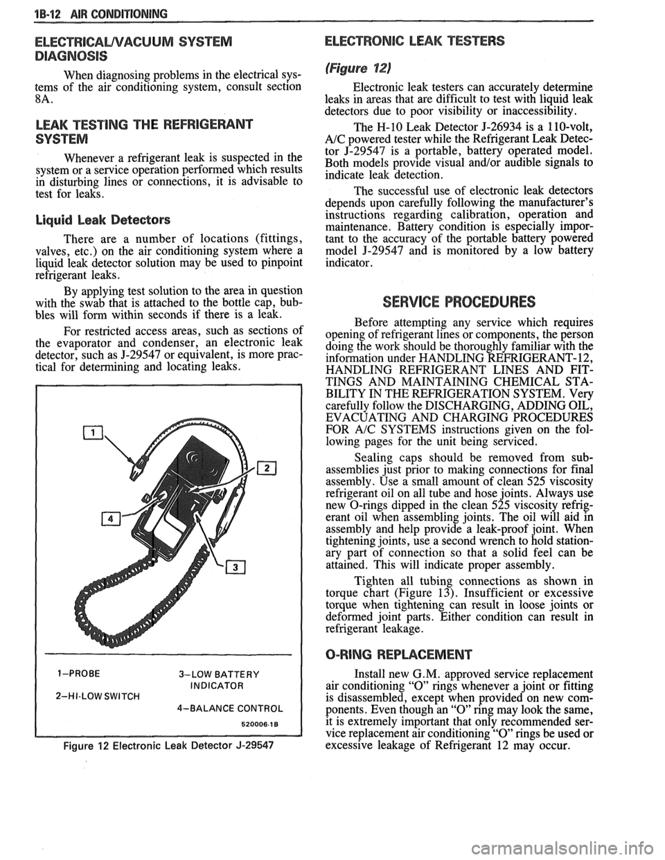
the evaporator and condenser, an electronic leak
detector, such as
5-29547 or equivalent, is more prac-
tical for determining and locating leaks.
3-LOW BATTERY
INDICATOR
2-HI-LOW SWITCH
4-BALANCE CONTROL
Figure 12 Electronic Leak Detector J-29547
ELECTRONIC LEAK TESTERS
(Figure 12)
Electronic leak testers can accurately determine
leaks in areas that are difficult to test with liquid leak
detectors due to poor visibility or inaccessibility.
The H-10 Leak Detector 5-26934 is a 110-volt,
A/C powered tester while the Refrigerant Leak Detec-
tor J-29547 is a portable, battery operated model.
Both models provide visual
and/or audible signals to
indicate leak detection.
The successful use of electronic leak detectors
depends upon carefully following the manufacturer's
instructions regarding calibration, operation and
maintenance. Battery condition is especially impor-
tant to the accuracy of the portable battery powered
model
5-29547 and is monitored by a low battery
indicator.
SERVICE PROCEDURES
Before attempting any service which requires
opening of refrigerant lines or components, the person
doing the work should be thoroughly familiar with the
information under HANDLING REFRIGERANT- 12,
HANDLING REFRIGERANT LINES AND FIT-
TINGS AND MAINTAINING CHEMICAL STA-
BILITY IN THE REFRIGERATION SYSTEM. Very
carefully follow the DISCHARGING, ADDING OIL,
EVACUATING AND CHARGING PROCEDURES
FOR
A/C SYSTEMS instructions given on the fol-
lowing pages for the unit being serviced.
Sealing caps should be removed from sub-
assemblies just prior to making connections for final
assembly. Use a small amount of clean 525 viscosity
refrigerant oil on all tube and hose joints. Always use
new O-rings dipped in the clean 525 viscosity refrig-
erant oil when assembling joints. The oil will aid in
assembly and help provide a leak-proof joint. When
tightening joints, use a second wrench to hold station-
ary part of connection so that
a solid feel can be
attained. This will indicate proper assembly.
Tighten all tubing connections as shown in
torque chart (Figure
13). Insufficient or excessive
torque when tightening can result in loose joints or
deformed joint parts. Either condition can result in
refrigerant leakage.
O-RING REPWCEMENT
Install new G. M. approved service replacement
air conditioning
"0" rings whenever a joint or fitting
is disassembled, except when provided on new com-
ponents. Even though an
"0" ring may look the same,
it is extremely important that only recommended ser-
vice replacement air conditioning
"0" rings be used or
excessive leakage of Refrigerant 12 may occur.
Page 57 of 1825
18-14 AIR CONDITIONING
HANDLING OF REFRIGERANT LINES AND
FI-INGS
Tighten all tubing connections as shown in
torque chart (Figure 13). INSUFFICIENT OR
EXCESSIVE TORQUE WHEN TIGHTENING CAN
RESULT IN LOOSE JOINTS OR DEFORMED
JOINT PARTS. Either condition can result in refrig-
erant leakage.
All metal tubing lines should be free of dents or
kinks to prevent loss of system capacity due to line
restriction.
@ The flexible hose lines should never be bent to a
radius of less than four (4) times the diameter of
the hose.
@ The flexible hose lines should never be allowed
to come within a distance of
63.5mm (2-112") of
the exhaust manifold.
@ Flexible hose lines should be inspected regularly
for leaks or brittleness and replaced with new
lines if deterioration or leaking is found.
@ When disconnecting any fitting in the refrigera-
tion system, the system must first be discharged
of all Refrigerant- 12. Proceed very cautiously
regardless of gauge readings. Open very slowly,
keeping face and hands away so that no injury
can occur if there happens to be liquid
Refriger-
ant-12 in the line. If pressure is noticed when
fitting is loosened, allow it to bleed off as
described under DISCHARGING, ADDING
OIL, EVACUATING AND CHARGING PRO-
CEDURES FOR
A/C SYSTEMS.
@ In the event any refrigerant line is opened to the
atmosphere, it should be immediately capped or
taped to prevent entrance of moisture and dirt,
which can cause internal compressor wear or
plugged lines, in the condenser and evaporator
core and expansion (orifice) tubes or compressor
inlet screens.
@ The use of the proper wrenches when making
connections on O-ring fittings is important. The
opposing fitting should always be backed up
with a wrench to prevent distortion of connecting
lines or components. When connecting the flexi-
ble hose connections, it is important that the
swaged fitting and the flare nut, as well as the
coupling to which it is attached, be held at the
same time using three
(3) different wrenches to
prevent turning the fitting and damaging the
ground seat.
@ O-rings and seats must be in perfect condition. A
burr or piece of dirt may cause a refrigerant leak.
When replacing the O-ring, first dip it in clean
525 viscosity refrigeration oil.
MAINTAINING CHEMICAL STABILITY IN
THE
REFRIGERATION SYSTEM
The efficient operation and life of the air condi-
tioning system is dependent upon the chemical stabil-
ity of the refrigeration system. When foreign materials, such as
dirt, air, or moisture, contaminate
the refrigeration system, they will change the stability
of the Refrigerant-12 and 525 viscosity compressor
oil. They will also affect pressure-temperature rela-
tionship, reduce efficient operation and possibly cause
interior corrosion and abnormal wear of moving parts.
The following general practices should be
observed to insure chemical stability in the system:
1. Before disconnecting a refrigerant connection,
wipe away any dirt or oil at and near the connec-
tion to reduce the possibility of dirt entering the
system. Both sides of the connection should be
capped, plugged or taped as soon as possible to
prevent the entry of dirt, foreign material and
moisture.
2. Keep tools clean and dry. This includes the
manifold gauge set and replacement parts.
3. When adding 525 viscosity refrigerant oil (see
ADDING OIL in the DISCHARGING,
ADDING OIL, EVACUATING AND
CHARGING PROCEDURES FOR
AIC SYS-
TEMS, the transfer device and container should
be clean and dry to assure that refrigeration oil
remains as moisture-free as possible.
4. When it is necessary to "open" an
AIC system,
have everything needed ready and handy so that
as little time as possible will be required to per-
form the operation. Do not leave the
AIC system
open any longer than is necessary.
5. Any time the
A/C system has been "opened," it
should be properly evacuated before recharging
with Refrigerant- 12 according to the DIS-
CHARGING, ADDING OIL, EVACUATING
& CHARGING PROCEDURES FOR AIC
SYSTEMS.
All service parts are dehydrated and sealed
prior to shipping. They should remain sealed until just
prior to making connections. All parts should be at
room temperature before uncapping. (This prevents
condensation of moisture from the air entering the
system.) If, for any reason, caps are removed but the
connections are not made, parts should be resealed as
soon as possible.
DISCHARGING, ADDING OIL,
EVACUATING AND CHARGING
PROCEDURES FOR NC SYSTEMS
The refrigerant system may be discharged,
evacuated and charged using air conditioning service
charging station J-23500-01 or equivalent, or the
manifold and gauge set
5-23575-01 and 420ml (14
oz.) disposable cans of Refrigerant-12 (Figure 16).
Charging lines from the charging station or
manifold and gauge set require the use of gauge
adapters to connect to the system service fitting.
A
straight gauge adapter 5-5420 and a 90" angle gauge
adapter
5-9459 are available (see A/C Special Tools).
Always wear goggles and wrap a clean cloth
around fittings and connections when doing work that
Page 58 of 1825
AIR GONDlTlONlNG 1B-15
involves opening the refrigeration system. Always
work in a well ventilated area and avoid breathing any
refrigerant fumes. If liquid refrigerant comes into con-
tact with the eyes, injury may result.
@ Before removing and replacing any of the air
conditioning refrigeration lines or components,
the system must be completely discharged of
Refrigerant- 12.
@ Always use service valve and pressure gauge
sets during evacuation and charging procedures.
@ Always discharge system at low-side service fit-
ting and perform the entire evacuate and charg-
ing procedure through the low-side service
fitting.
@ Do not connect high-pressure line or any line to
the high-side
service fitting during discharging
and charging procedures.
CAUTION: Never remove a gauge line
from its adapter when line is connected
to
AIC system. Always remove the line
adapter from the service
fining to dis-
connect a line. Do not remove charging
hose at gauge set while
anached to ser-
vice low-side
fining. This will result in
complete discharge of system due to
the depressed Schrader valve in
service
low-side fining and may cause personal
injury due to escaping Refrigerant-12.
Discharging the NG System
In replacing any of the air conditioning refriger-
ation components, the system must be completely dis-
charged of Refrigerant- 12.
ALWAYS DISCHARGE SYSTEM AT
LOW-SIDE SERVICE FITTING.
1. With ignition turned "OFF," remove protective
cap from LOW-SIDE service fitting (on most
models) on Accumulator and connect charging
station
J-23500-01 or equivalent gauge set. If
charging station J-23500-01 or equivalent is not
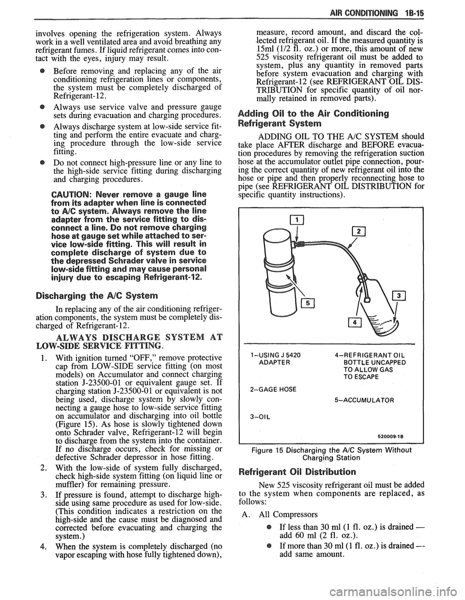
being used, discharge system by slowly con-
necting a gauge hose to low-side
sewice fitting
on accumulator and discharging into oil bottle
(Figure 15). As hose is slowly tightened down
onto Schrader valve, Refrigerant-12 will begin
to discharge from the system into the container.
If no discharge occurs, check for missing or
defective Schrader depressor in hose fitting.
2. With the low-side of system fully discharged,
check high-side system fitting (on liquid line or
muffler) for remaining pressure.
3. If pressure is found, attempt to discharge high-
side using same procedure as used for low-side.
(This condition indicates a restriction on the
high-side and the cause must be diagnosed and
corrected before evacuating and charging the
system.)
4. When the system is completely discharged (no
vapor escaping with hose fully tightened down), measure, record
amount, and discard the col-
lected refrigerant oil. If the measured quantity is
15ml (112 fl. 02.) or more, this amount of new
525 viscosity refrigerant oil must be added to system, plus any quantity in removed parts
before system evacuation and charging with
Refrigerant-12 (see REFRIGERANT OIL DIS-
TRIBUTION for specific quantity of oil nor-
mally retained in removed parts).
Adding Oil to the Air Conditioning
Refrigerant System
ADDING OIL TO THE A/C SYSTEM should
take place AFTER discharge and BEFORE evacua-
tion procedures by removing the refrigeration suction
hose at the accumulator outlet pipe connection, pour-
ing the correct quantity of new refrigerant oil into the
hose or pipe and then properly reconnecting hose to
pipe (see REFRIGERANT OIL DISTRIBUTION for
specific quantity instructions).
1-USING J 5420 4-REFRIGERANT OIL BOTTLE UNCAPPED
TO ALLOW GAS
TO ESCAPE
2-GAGE HOSE 5-ACCUMULATOR
Figure 15 Discharging the A/C System Without
Charging Station
Refrigerant Oil Distribution
New 525 viscosity refrigerant oil must be added
to the system when components are replaced, as
follows:
A. All Compressors
@ If less than 30 ml(1 fl. oz.) is drained -
add 60 ml (2 fl. oz.).
@ If more than 30 ml(1 fl. oz.) is drained --
add same amount.
Page 80 of 1825
W-4 AIR CONDITIONING COMPRESSOR OVERHAUL 1 Dl-l
SECTION 1 Dl
R COND NG COMPRESSOR
OVERHAUL
For Compressor REMOVAL AND INSTALLATION, see Air Conditioning Section 1B. For
DISCHARGING, ADDING OIL, EVACUATING AND CHARGING PROCEDURES FOR
A/C
SYSTEMS, see Air Conditioning Section 1B.
CONTENTS
General Description ............................... 1D1-1
Service Procedures .................................. 1D1-4
Minor Repair Procedures ....................... 1D1-4
Clutch Plate and Hub Assembly ............... 1D1-4
Clutch Rotor and Bearing: Four-Pole
Clutch
..................................................... 1D1-5
Clutch Rotor and Bearing: Six-Pole
Clutch
.......................... ... ....................... 1 D 1-7
Clutch Coil and Pulley Rim ...................... 1 D 1 - 10
Major Repair Procedures ....................... 1D1-12
Shaft Seal .................................................. 1Dl-12
Seal Leak Detection ........................... .... 1D1-12
Replacement (On Car) ........................... 1 D 1- 12
Replacement (Off Car)
........................... 1 D 1 - 13
Pressure Relief Valve
................................. 1 D 1 - 13
Nigh Pressure Cut-Off Switch
................... 1 D 1 - 13
Front Head and 0-Ring
............................ 1 D 1 - 14
Thrust and Belleville Washers
................... 1 D 1 - 16
Main Bearing
.............................................. 1 D 1- 16
Shell and 0-Ring
....................................... 1D 1- 17
Discharge Valve Plate and Retainer
......... 1 D 1 - 18
Cylinder and Shaft Assembly
.................... 1 D 1 - 19
Leak Testing (External and Internal)
........ 1D1- 19
Special Tools ..................................... ... .. 1D1-21
GENERAL DESCRIPTION
M22 X 1.5 THREAD M22 X 1.5 THREAD
6 POLE DRIVER- 4 POLE DRIVER-
SHORT SHAFT SHORT SHAFT
J20001.1 Dl
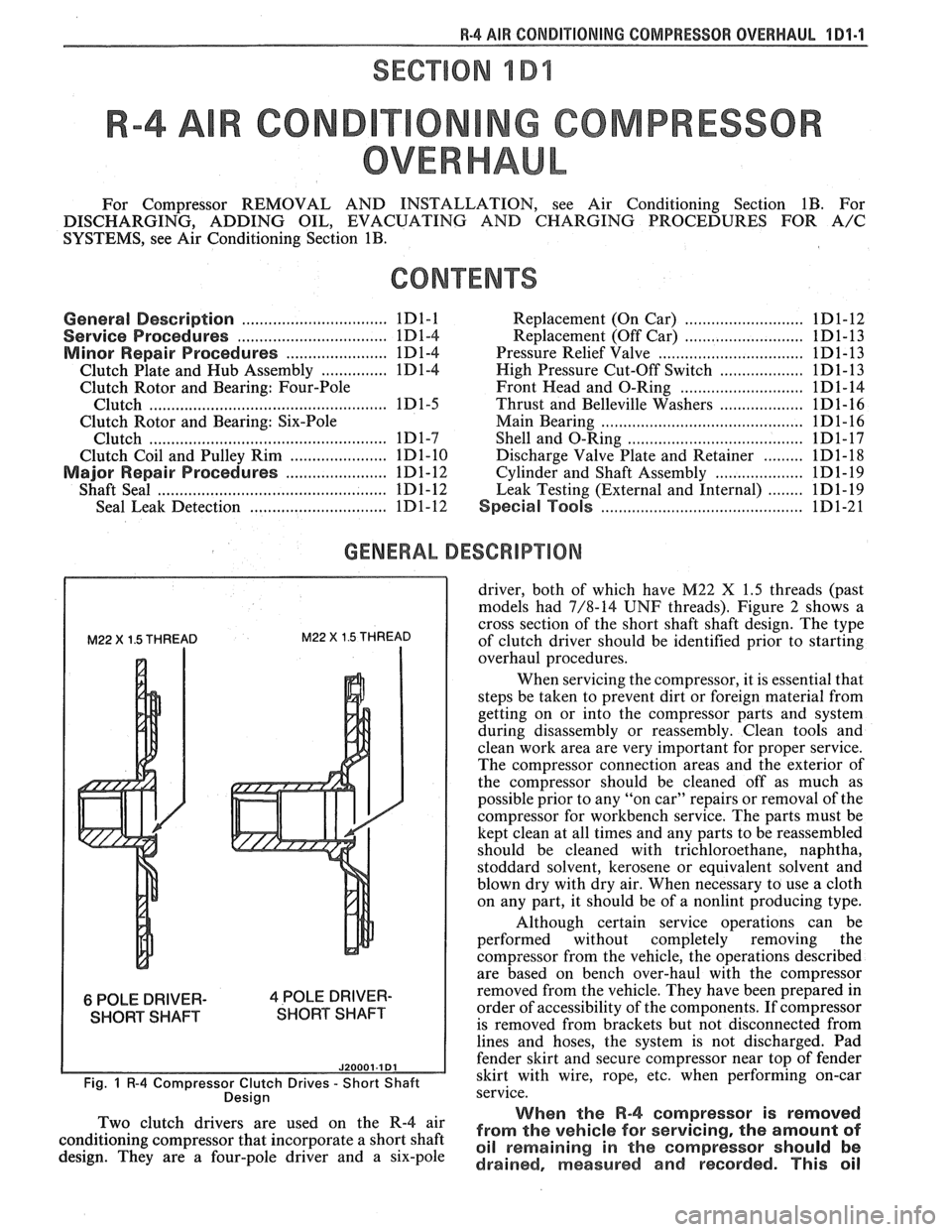
Fig. 1 R-4 Compressor Clutch Drives - Short Shaft
Desian
driver, both of which have M22 X 1.5 threads (past
models had 7/8-14
UNF threads). Figure 2 shows a
cross section of the short shaft shaft design. The type
of clutch driver should be identified prior to starting
overhaul procedures.
When servicing the compressor, it is essential that
steps be taken to prevent dirt or foreign material from
getting on or into the compressor parts and system
during disassembly or reassembly. Clean tools and
clean work area are very important for proper service.
The compressor connection areas and the exterior of
the compressor should be cleaned off as much as
possible prior to any "on car" repairs or removal of the
compressor for workbench service. The parts must be
kept clean at all times and any parts to be reassembled
should be cleaned with trichloroethane, naphtha,
stoddard solvent, kerosene or equivalent solvent and
blown dry with dry air. When necessary to use a cloth
on any part, it should be of a nonlint producing type.
Although certain service operations can be
performed without completely removing the
compressor from the vehicle, the operations described
are based on bench over-haul with the compressor
removed from the vehicle. They have been prepared in
order of accessibility of the components. If compressor
is removed from brackets but not disconnected from
lines and hoses, the system is not discharged. Pad
fender skirt and secure compressor near top of fender
skirt with wire, rope,
etc, when performing on-car
service.
., When the R-4 compressor is removed Two 'lutch drivers are wed On the R-4 air from the vehicle for servicing, the amount of conditioning compressor that incorporate a short shaft oil remaining in the should be design. They are a four-pole driver and a six-pole drained, measured and recorded. This oil
Page 302 of 1825
BRAKES 5-9
TUBE hlUST BE
SUBMERGED IN
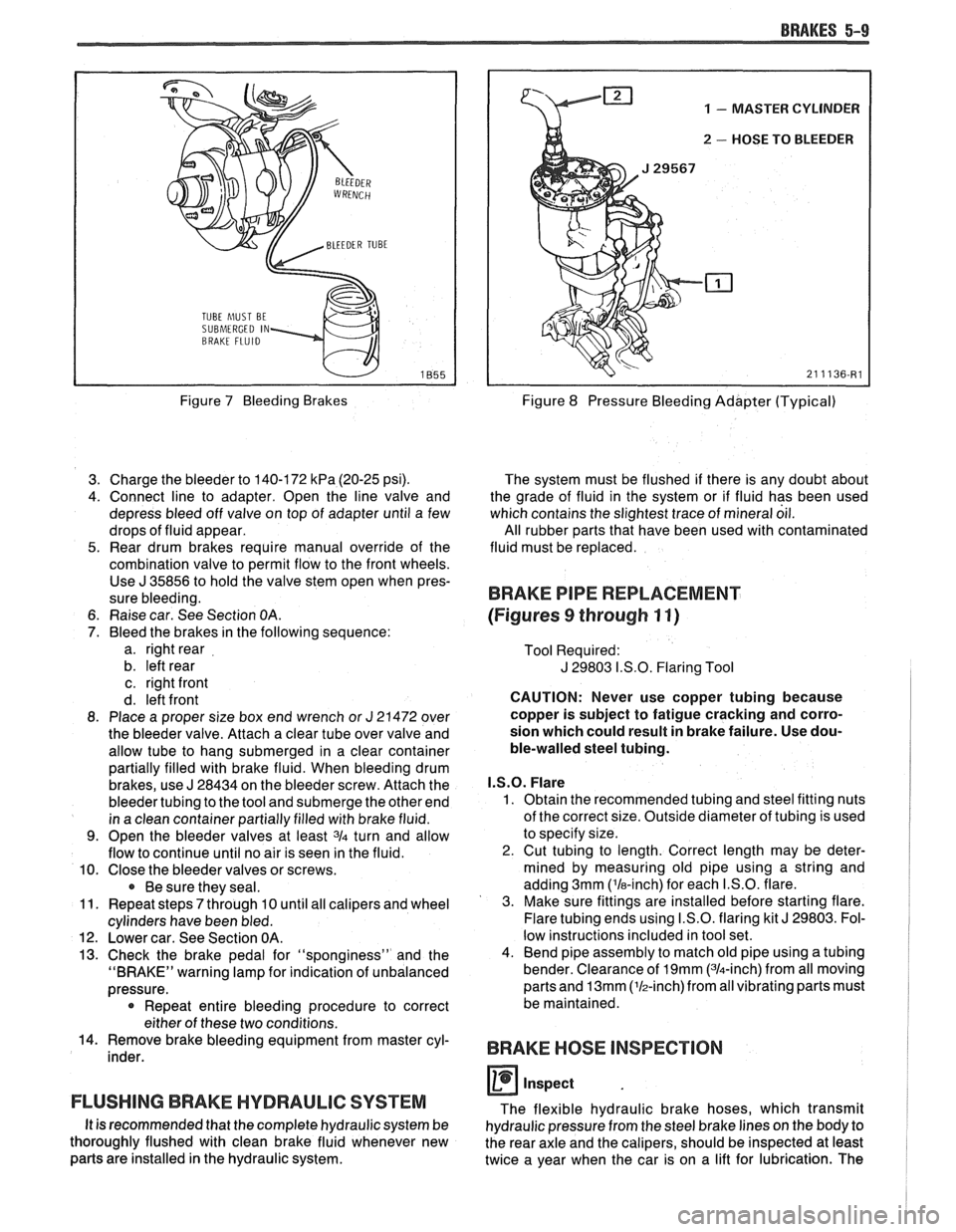
Figure 7 Bleeding Brakes
3. Charge the bleeder to 140-172
kPa (20-25 psi).
4. Connect line to adapter. Open the line valve and
depress bleed off valve on top of adapter until a few
drops of fluid appear.
5. Rear drum brakes require manual override of the
combination valve to permit flow to the front wheels. Use
J 35856 to hold the valve stem open when pres-
sure bleeding.
6. Raise car. See Section
OA.
7. Bleed the brakes in the following sequence:
a. right rear
b. left rear
c. right front
d. left front
8. Place a proper size box end wrench or
J 21472 over
the bleeder valve. Attach a clear tube over valve and
allow tube to hang submerged in a clear container
partially filled with brake fluid. When bleeding drum
brakes, use
J 28434 on the bleeder screw. Attach the
bleeder tubing to the tool and submerge the other end
in a clean container partially filled with brake fluid.
9. Open the bleeder valves at least 3/4 turn and allow
flow to continue until no air is seen in the fluid.
10. Close the bleeder valves or screws.
Be sure they seal.
11. Repeat steps
7 through 10 until all calipers and wheel
cylinders have been bled.
12. Lower car. See Section OA.
13. Check the brake pedal for "sponginess" and the
"BRAKE" warning lamp for indication of unbalanced
pressure.
* Repeat entire bleeding procedure to correct
either of these two conditions.
14. Remove brake bleeding equipment from master cyl-
inder.
FLUSHING BRAKE HYDRAULIC SYSTEM
It is recommended that the complete hydraulic system be
thoroughly flushed with clean brake fluid whenever new
parts are installed in the hydraulic system.
1 - MASTER CYLINDER
u 2 - HOSE TO BLEEDER
Figure 8 Pressure Bleeding Adapter (Typical)
The system must be flushed if there is any doubt about
the grade of fluid in the system or if fluid has been used
which contains the slightest trace of mineral oil.
All rubber parts that have been used with contaminated
fluid must be replaced.
BRAKE PIPE REPLACEMENT
(Figures
9 through 11)
Tool Required:
J 29803 I.S.O. Flaring Tool
CAUTION: Never use copper tubing because
copper is subject to fatigue cracking and corro-
sion which could result in brake failure. Use dou-
ble-walled steel tubing.
I.S.O. Flare
1. Obtain the recommended tubing and steel fitting nuts
of the correct size. Outside diameter of tubing is used
to specify size.
2. Cut tubing to length. Correct length may be deter-
mined by measuring old pipe using a string and
adding 3mm ('la-inch) for each I.S.O. flare.
3. Make sure fittings are installed before starting flare.
Flare tubing ends using I.S.O. flaring kit
J 29803. Fol-
low instructions included in tool set.
4. Bend pipe assembly to match old pipe using a tubing
bender. Clearance of
19mm (314-inch) from all moving
parts and
13mm (lh-inch)from all vibrating parts must
be maintained.
BRAKE HOSE INSPECTION
0 inspect
The flexible hydraulic brake hoses, which transmit
hydraulic pressure from the steel brake lines on the body to
the rear axle and the calipers, should be inspected at least
twice a year when the car is on a lift for lubrication. The
Page 418 of 1825
ENGINE COOLING BB-7
NOTICE: If recommended quality antifreeze is
used, supplemental inhibitors or additives claiming
to provide increased cooling capability are not
necessary. They may be detrimental to the efficient
operation of the system, and represent an
unnecessary operating expense.
Every 12 months or 15,000 miles, the cooling
system should be serviced as follows;
1. Wash radiator cap and filler neck with clean
water.
2. Check coolant for proper level and freeze
protection.
3. Pressure test system and radiator cap for proper
pressure holding capacity, 103
kPa (15 psi). If
replacement of cap is required, use the proper cap
specified for car model.
4. Tighten hose clamps and inspect all hoses. Replace
hoses whenever cracked, swollen or otherwise
deteriorated.
5. Clean frontal area of radiator core and air
conditioning condenser.
DRAINING AND REFILLING THE COOLING
SYSTEM
Replace hoses every 24 months or 30,000 miles or
earlier if cracked, swollen or otherwise deteriorated.
Every two years or 30,000 miles, whichever first
occurs, the cooling system should be flushed and
refilled using the following recommended procedure:
1. Remove radiator cap, or thermostat housing cap
(VIN
0, J, R and U), when engine is cool by:
a. Slowly
rotating cap counterclockwise to
detent. (Do not press down while rotating.)
b. Wait until any
residual pressure (indicated
by a hissing sound) is relieved.
c. After all hissing ceases, press down on cap
while continuing to rotate
counterclockwise.
CAUTION: To avoid the danger of
being burned, do not remove radiator
cap while engine and radiator are still
hot. Scalding fluid and steam may be
blown out under pressure.
2. Remove the thermostat by using the wire handle
to lift it out of the housing (VIN
0, J, R and U).
3. With the thermostat removed, reinstall the
thermostat housing cap (VIN
0, J, R and U).
4. Open radiator drain valve and block drain plugs
to drain coolant. On VIN R and
9 (P series)
engines, open coolant pipe plugs.
5. Close valve. Reinstall drain plugs, and add
sufficient water to fill system.
6. Run engine, drain and refill the system, as
described in steps
4 and 5 a sufficient number of
times, until the drained liquid is nearly colorless.
Important
BLOCK DRIVE WHEELS, place
transmission in PARK (automatic
transmission) or NEUTRAL (manual
transmission) and set the parking brake. 7.
Allow system to drain completely. Then close
radiator drain valve tightly, and reinstall block
drain plugs.
8. Remove recovery cap leaving hoses in place.
Remove coolant recovery tank and empty of
fluid. Flush tank with clean water, drain and
reinstall.
9. Add sufficient ethylene glycol coolant, meeting
GM specification 1825-M, to provide the
required freezing and corrosion protection
- at
least 50 percent solution -37°C (-34°F). Fill
radiator to the base of the radiator fill neck and
add sufficient coolant to the recovery tank to
raise level to the "FULL" mark. Reinstall
recovery tank cap.
10. Run engine, with radiator cap or thermostat
housing cap removed, until normal operating
temperature is reached. (Radiator upper hose
becomes hot.)
11. With engine idling, add coolant until level
reaches bottom of filler neck and reinstall cap,
making certain arrows line up with overflow tube.
CAUTION: Under some conditions, the
ethylene glycol in engine coolant is
flammable. To help avoid being
burned when adding coolant, DO NOT
spill
it on the exhaust system or hat
engine parts.
It is the owner's responsibility to keep the freeze
protection at a level appropriate to the
temperatures which may occur in the area of
vehicle operation.
a. Maintain
cooling system freeze protection
at
-37°C (-34"F), to ensure protection
against corrosion and loss of coolant from
boiling, even though freezing temperatures
are not expected.
b. Add ethylene glycol base coolant that meets
GM Specification 1825-M, when coolant
additions are required because of coolant
loss, or to provide additional protection
against
freezing at temperatures lower than
-37°C (-34°F).
NOTICE: Alcohol or methanol base coolants, or
plain water, are not recommended at any time.
DRlVE BELT
NOTICE: Routine inspection of the belt may
reveal cracks in the belt ribs. These cracks will
not impair belt performance and therefore should
not be considered a problem requiring belt
replacement. However, the belt should be
replaced if belt slip occurs or if sections of the
belt ribs are missing.
A single (serpentine) belt is used to drive all
engine accessories formerly driven by multiple drive
belts. All belt driven accessories are ridgedly mounted
with belt tension maintained by a spring loaded
tensioner.
The drive belt tensioner has the ability to control
belt tension over a fairly broad range of belt lengths.
Page 419 of 1825
68-8 ENGINE COOLING
However, there are limits to the tensioner's ability to
The tensioner has rovisions for a visual check to
compensate for varying lengths of belts. With the
ten- verify that it is in t e "operating range" (see Figures
sioner outside of its operating range, poor tension
608 and 609). R
control andlor damage to the tensioner may result.
ALUMINUM RADIATOR REPAIR
This radiator utilizes an aluminum core with
plastic side tanks. The core and side tanks can be
replaced separately and core repair is easily made with
the hot melt adhesive method. A transaxle oil cooler
is located in one of the side tanks. The oil cooler can
be replaced. The drain cock is located on the lower part
of one of the tanks. The drain cock is also serviceable.
Core
The core is made of aluminum and is of the
crossflow design. It utilizes large tubes that resist
plugging, and repairs to the tubes and core are easily
made using the hot melt adhesive method.
The core is attached to the tanks by clinched tabs
on the core that can be bent back if tank or core
replacement is required.
If the damage to a tube is too severe, a tube can
be blocked or plugged as explained in "Tube Blocking.
" No more than two tubes should ever be blocked on
a core. Also replace the core if more than three tabs are
broken on one side, or if two adjacent tabs are broken.
Tanks
The tanks are attached to the core by the use of
clinched tabs. The clinched tabs can be bent back if the
tanks need to be removed from the core. Bend the tabs
back only enough to remove the tank. Overbending
will weaken the tabs.
A high temperature rubber gasket is used to seal
the mating surface between the core and the tank. (See
Fig. 8). The gasket must be replaced any time a tank
is removed from the core.
Transaxle Oil Cooler
The transaxle oil cooler is located in one of the
radiator side tanks. The oil cooler can be replaced by
removing the tank from the core.
A leaking oil cooler gasket can be replaced
without removing the tank from the core.
Drain Cock
The aluminum/plastic radiator utilizes a two
piece plastic drain cock and a rubber seal. The drain
cock is serviceable (See Fig.
9).
ALUMINUM RADIATOR SERVICE
The aluminum-plastic radiator can be repaired at
the dealership. The following components are easily
replaced:
e Core
e Tanks and gaskets
o Oil coolers and gaskets
e Drain cock and gasket The
tanks cannot be repaired if broken or
cracked. The radiator core can be replaced and the new
core used with the original tanks and oil cooler.
Precautions
As with all cooling system service, take measures
to prevent personal injury and damage to the system.
CAUTION: To help avoid the danger of
being burned, do not remove the
radiator cap while the engine and
radiator are
still hot. Scalding fluid
and steam can be blown out under
pressure if the
cap is taken off too
soon.
NOTICE: DO NOT USE "BOIL OUT" TANKS
OR VATS. Common service methods may
actually destroy an aluminum radiator. Caustic or
lye cleaning solutions must NOT be used for
aluminum radiators.
e Do not open the hood if you can see, or hear,
steam or coolant escaping from the engine
compartment.
e Do not remove radiator cap if radiator feels
warm.
e Do not remove the radiator cap or coolant
recovery tank cap if the coolant in the recovery
tank looks like it is boiling.
Wear eye protection.
e Wear gloves to protect your hands against
excessive heat, or the effects of chemicals on your
skin.
o Prevent dirt and water from entering the
transmission oil cooler.
e Do not use boil-out tanks, or vats, or other tanks
that have been used for copper and brass
radiators. The flux, acid, and caustic cleaners
remaining in these tanks will attack the
aluminum and cause radiator failure.
A separate
test tank containing clean water is strongly
recommended for servicing aluminum-plastic
radiators.
RIOTICE: Never use shop air that is not regulated
at
20 psi (138 kPa) to pressure test radiator.
Pressures over
20 psi (138 kPa) will damage the
radiator.
DIAGNOSIS
Leak Testing
Some core leaks can be detected by merely adding
water to the radiator. It is helpful to clean the core so
that the damaged area can be more easily found.
Page 1158 of 1825
CLUTCH 7C-4
SECTION 76
CLUTCH
CONTENTS
GENERAL DESCRIPTION .......................... .. ............................................................. 7C-I
DIAGNOSIS ...................................................................................................................... 7C-3
Preliminary Checks ....................... ... ............................................................................ 7C-2
Bleeding Hydraulic Clutch System ................... .. .......................................................... 7C-2
ON-VEHICLE SERVICE ................................................................................................. 7C-5
Clutch Hydraulic System ................................................................................................. 7C-5
..................... Pressure Plate and Disc .. ........................................................................... 7C-6
Clutch Pedal ..................................................................................................................... 7C-6
Pilot Bearing .................................................................................................................. 7C-6
....................................................................................................... SPECIFICATIONS 7C-8
............................................................................................................ SPECIAL TOOLS 7C-8
GENERAL DESCRIPTION
COMPONENTS
The principal parts of a clutch system are: the
driving member and the operating members. Figure
7C-1 shows an exploded view of the clutch system.
DRIVEN MEMBERS (FIGURES 7C-1 AND 7C-2)
The driven member is the clutch disc with a
splined hub which is free to slide lengthwise along the
splines of the input shaft, but which drives the input
shaft through these same splines.
The driving and driven members are held in
contact by spring pressure. This pressure is exerted by
a diaphragm spring in the pressure plate assembly.
HYDRAULIC CLUTCH (FIGURE 7C-3)
A hydraulic clutch operating mechanism is used
on all models. The
mechanism consist of a remote
reservoir, clutch master cylinder and slave cylinder.
The remote reservoir is mounted to a bracket which
bolts to the power brake booster. The clutch master
cylinder is mounted on the cowl panel and the slave
cylinder is mounted on the bell housing. The clutch
master cylinder is operated directly off the clutch
pedal.
When the clutch pedal is pressed down, hydraulic
fluid under pressure from the clutch master cylinder
flows into the slave cylinder. Since the piston is also
connected to the clutch fork this lever moves the
release bearing into contact with the clutch cover
release fingers to disengage the clutch. The hydraulic
clutch system locates the clutch pedal height and
provides automatic clutch adjustment. No adjustment
of clutch linkage or pedal position is required.
OPERATING MEMBERS (FIGURE 7C-3)
HYDRAULIC CLUTCH FLUID
When adding fluid to or refilling the system after
The clutch release system is operated by service operations use GM Delco Supreme No. 11 hydraulic pressure and consists of the clutch pedal, brake fluid or an equivalent fluid that meets DOT 3 clutch master cylinder, clutch slave cylinder, clutch specifications. fork and clutch release bearing.
NOTICE: Do not use mineral or paraffin base oil in
the Clutch Hydraulic System. These fluids will
damage the rubber parts in the cylinders.