fuse diagram PONTIAC FIERO 1988 Service Repair Manual
[x] Cancel search | Manufacturer: PONTIAC, Model Year: 1988, Model line: FIERO, Model: PONTIAC FIERO 1988Pages: 1825, PDF Size: 99.44 MB
Page 501 of 1825
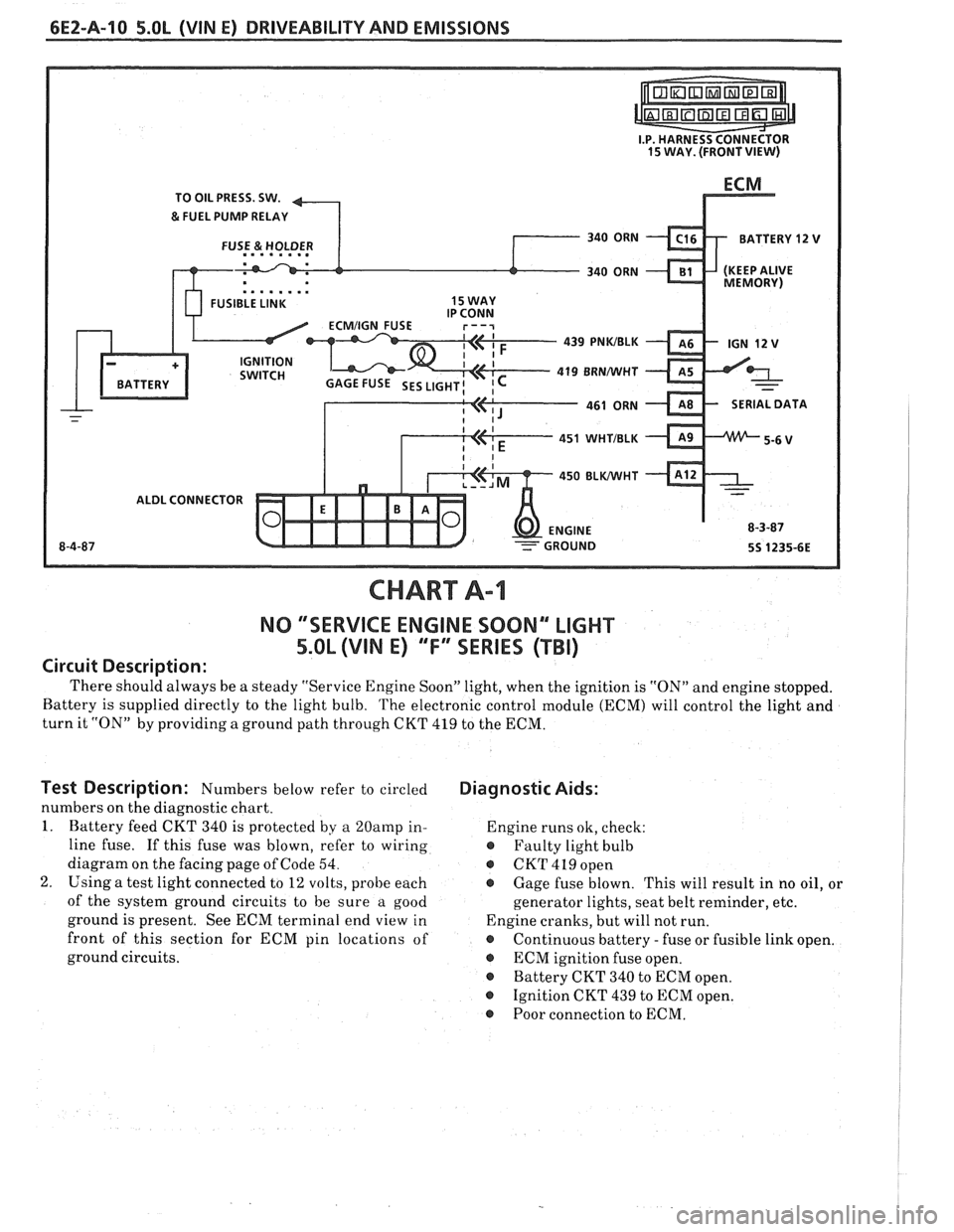
6EZ-A-10 5.0L (VIN E) DRIVEABILITY AND EMISSIONS
TO OIL PRESS. SW.
&FUEL PUMP RELAY
BATTERY
12 V
. . . . . . . . FUSIBLE LINK 15 WAY
439 PNWBLK
419
BRNNVHT
SERIAL DATA
451
WHTIBLK
450 BLWHT
ALDL CONNECTOR
NO "SERVICE ENGINE SOON" "LIGHT
5.OL (VIN E) "F'" SERIES (TBI)
Circuit Description:
There should always be a steady "Service Engine Soon" light, when the ignition is "ON" and engine stopped.
Battery is supplied directly to the light bulb.
The electronic control module (ECM) will control the light and
turn it "ON" by providing a ground path through CKT 419 to the ECM.
Test Description: Numbers below refer to circled
numbers on the diagnostic chart.
1. Battery feed CKT 340 is protected by a
20amp in-
line fuse. If this fuse was blown, refer to wiring
diagram on the facing page of Code 54.
2. Using a test light connected to 12 volts, probe each
of the system ground circuits to be sure
a good
ground is present. See ECM terminal end view in
front of this section for ECM pin locations of
ground circuits.
Diagnostic Aids:
Engine runs ok, check:
@ Faulty light bulb
@ CKT419open
@ Gage fuse blown. This will result in no oil, or
generator lights, seat belt reminder, etc.
Engine cranks, but will not run.
@ Continuous battery - fuse or fusible link open.
@ ECM ignition fuse open.
@ Battery CKT 340 to ECM open.
o Ignition CKT 439 to ECM open.
@ Poor connection to ECM.
Page 663 of 1825
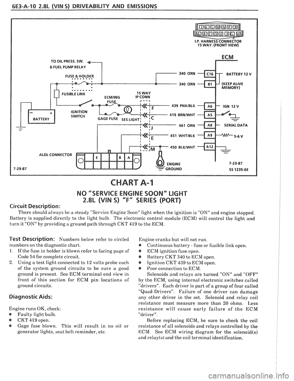
6E3-A-"I 2.8L (VlN S) DRIVEABILITY AND EMlSSlONS
TO OIL PRESS. SW.
&FUEL PUMP RELAY
FUSE
81 HOLDER BATTERY 12 V .. m.. . n.
. . . . . . . . FUSIBLE LINK
439 PNWBLK
419 BRNNVHT
SERIAL
DATA
451
WHTJBLK
450 BLKNVHT
ALDL CONNECTOR
NO "SERVICE ENGlNE SOON" "LIGHT
2.8b (VIM 5) 'T" "SERIES (PORT)
Circuit Description:
There should always be a steady "Service Engine Soon" light when the ignition is "ON" and engine stopped.
Battery is supplied directly to the light bulb. The electronic control module
(ECNI) will control the light and
turn it "ON" by providing a ground path through CKT 419 to the ECM.
Test Description: Numbers below refer to circled
numbers on the diagnostic chart.
1. If the fuse in holder is blown refer to facing page of
Code
54 for complete circuit.
2. Using a test light connected to 12 volts probe each
of the system ground circuits to be sure a good
ground is present. See ECM terminal end view in
front of this section for
ECM pin locations of
ground circuits.
Diagnostic Aids:
Engine runs OK, check:
@ Faulty light bulb.
@ CKT 419 open.
@ Gage fuse blown.
This will result in no oil or
generator lights, seat belt reminder, etc. Engine
cranks but will not run.
@ Continuous battery - fuse or fusible link open.
@ ECM ignition fuse open.
@ Battery CKT 340 to ECM open.
@ Ignition CKT 439 to ECM open.
e Poor connection to ECM.
Solenoids and relays are turned "ON"
and "OFF"
by the ECM, using internal electronic switches called
"drivers". Each driver is part of a group of four called
"Quad-Drivers". Failure of one driver can damage
any other driver in the set. Solenoid and relay coil
resistance must measure more than 20 ohms. Less
resistance will cause early failure of the ECM
"driver".
Before replacing ECM, be sure to check the coil
resistance of all solenoids and relays controlled by the
ECM. See ECM wiring diagram for the
solenoid(s)
and relay(s) and the coil terminal identification.
Page 711 of 1825
6E3-B-2 2.8L (VIN 5) DRIVEABILITY AND EMISSIONS
Problem may or may not turn "ON" the "Service Engine SoonJ' light, or store a code.
DO NOT use the trouble code charts in Section
"A" for intermittent problems. The fault must be
present to locate the problem. If a fault is
intermittent, use of trouble code charts may result
in replacement of good parts.
@ Most intermittent problems are caused by
faulty electrical connections or wiring. Perform
careful check as described at start of Section
"B". Check for:
@ Poor mating of the connector halves, or
terminals not fully seated in the connector
body (backed out).
@ Improperly formed or damaged terminals.
All connector terminals in problem circuit
should be carefully reformed to increase
contact tension.
@ Poor terminal to wire connection. This
requires removing the terminal from the
connector body to check. See "Introduction"
to Section
"6E".
@ If a visual check does not find the cause of the
problem, the car can be driven with a voltmeter
connected to a suspected circuit. A "Scan" tool
can also be used for monitoring input signals to
the ECM to help detect intermittent conditions.
An abnormal voltage, or "Scan" reading, when
the problem occurs, indicates the problem may
be in that circuit. If the wiring and connectors
check OK and a trouble code was stored for a
circuit having a sensor, except for Codes
43, 44,
and 45, substitute a known good sensor and
recheck. An
intermittent "Service Engine Soon" light
with no stored code may be caused by:
@ Ignition coil shorted to ground and arcing at
spark plug wires or plugs.
@ "Service Engine Soon" light wire to ECM
shorted to ground. (CKT 419).
@ Diagnostic "Test" terminal wire to ECM,
shorted to
ground.(CKT 451)
@ ECM power grounds. See ECM wiring
diagrams.
@ Loss of trouble code memory. To check,
disconnect TPS and idle engine until "Service
Engine Soon" light comes "ON". Code
22 should
be stored, and kept in memory when ignition is
turned "OFF". If not, the ECM is faulty.
@ Check for an electrical system interference
caused by a defective relay, ECM driven
solenoid, or switch. They can cause
a sharp
electrical surge. Normally, the problem will
occur when the faulty component is operated.
@ Check for improper installation of electrical
options, such as lights, 2-way radios, etc.
@ EST wires should be kept away from spark plug
wires, distributor wires, distributor housing,
coil, and generator. Wire from ECM to
distributor (CKT
453) should be a good
connection.
@ Check for open diode across A/C compressor
clutch, and for other open diodes (see wiring
diagrams).
HARD START
Definition: Engine cranks OK, but does not start for a long
time. Does eventually run, or may start hut immediately dies.
@ Perform careful check as described at start of -
Section "B".
@ Make sure driver is using correct starting
procedure.
@ CHECK:
- TPS for sticking or binding or a high TPS
voltage with the throttle closed (should read
less than
,700 volts).
- High resistance in coolant sensor circuit or
sensor itself. See Code 15 chart or with
a.
"Scan" tool compare coolant temperature with
ambient temperature on
a cold engine. 8
- Fuel pressure CHART A-7. Water contaminated
fuel.
EGR operation. Be sure valve seats properly and
is not staying open. See CHART C-7.
Both injector fuses (visually inspect).
Ignition system
- Check distributor for:
Proper output with ST-125.
Worn shaft.
Bare and shorted wires.
Pickup coil resistance and connections.
Loose ignition coil ground.
Moisture in distributor cap.
If problem exists in cold weather, check cold start
valve. See CHART A-9.
Page 723 of 1825
6E3-Cl-4 2.8L (VIN S) DRIVEABILITY AND EMISSIONS
BarWNeutral Switch (Auto Only)
The ParWNeutral (PIN) switch indicates to the
ECM when the transmission is in Park or Neutral.
This information is used for the TCC and the IAC
valve operation.
Important
Vehicle should not be driven with ParWNeutral
switch disconnected as idle quality will be affected
and a possible false Code
24 (VSS).
See Section "$A" for more information on the PIN
switch, which is part of the neutrallstart and backup
light switch assembly.
NC '"n" Signal
This signal tells the ECM that the A/C selector
Switch is turned on, and that the pressure cycling
switch is closed. The ECM uses this to adjust the idle
Speed when the air conditioning is working.
If this signal is not available to the ECM, idle may
be rough, especially when the
A/C compressor cycles.
The voltage at ECM terminal "B8" should equal
battery voltage when
AIC is requested and the
pressure cycling switch is closed.
The signal at
B8 will cause the ECM to turn on the
A/C clutch by energizing the A/C relay.
Distributor Reference Signal
The distributor sends a signal to the ECM to tell it
both engine RPM and crankshaft position. See EST
System for further information.
To read the codes, use a "Scan" tool or ground the
diagnostic terminal with the engine not running and
the ignition on. The "Service Engine Soon" light will
flash Code 12 three times and
then flash each code
stored in memory three times. All codes stored in
memory would have been read when Code 12 was
flashed again. No new codes can be stored when in the
Diagnostics Mode (diagnostics lead grounded).
This
eliminates confusion while the system is being worked
on. To clear the codes from memory:
@ Ignition off
@ Remove fuse located in a weather proof holder
located near the battery for 30 seconds.
Since the ECM can have
a failure which may
effect only one circuit, following the Diagnostic
Procedures in this section will determine which circuit
has a problem and where it is. If
a diagnostic chart indicates that the ECM
connections or ECM is the cause of
a problem and the
ECM is replaced, but does not correct the problem, one
of the following may be the reason:
€9
connections. - The diagnostic chart will say "ECM
connections or ECM. The terminals may have to be
removed from the connector in order to check them
properly.
@ The ECM or PROM is not correct for the
application.
- The incorrect components may cause a
malfunction and may or may not set a code.
@ The problem is intermittent. - This means that
the problem is not present at the time the system is
being checked. In this case, refer to the "Symptoms"
portion of the manual and make a careful physical
inspection of all portions of the system involved.
@ Shorted solenoid, relay coil, or harness. -
Solenoids and relays are turned "ON" and "OFF" by
the
ECM,using internal electronic switches called
"Drivers". Each driver is part of
a group of four called
"Quad-drivers". Failure of one driver can damage any
other driver in the set.
Solelloid and relay coil
resistance must measure more than 20 ohms. Less
resistance will cause early failure of the ECM
"driver". A shorted solenoid, relay coil, or harness,
with a GMP4 computer, will not damage the ECM, but
will cause the component to be inoperative.
Before replacing an ECM, be sure to check the coil
resistance of all solenoids and relays controlled by the
ECM. See ECM wiring diagram for the
solenoid(s)
and relay(s) and the coil terminal identification.
534636 or BT 8405 testers or equivalent provide
a fast, accurate means of checking for a shorted coil or
a short to battery voltage.
@ The PROM may be faulty. - Although these
rarely fail, it operates as part of the ECM. Therefore,
it could be the cause of the problem. Substitute a
known good PROM.
@ The replacement ECM may be faulty. - After the
ECM is replaced, the system should be rechecked for
proper operation. If the diagnostic chart again
indicates the ECM is the problem, substitute
a known
good ECM. Although this is a rare condition, it could
happen.
ECM
A faulty ECM will be determined in the diagnostic
charts or
by a Code 55.
PROM
A faulty PROM may result in a Code 51.
Page 867 of 1825
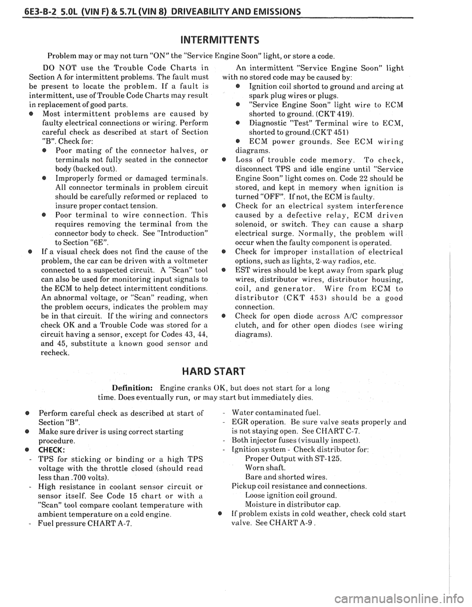
6E3-B-2 5.OL (VIN F) & 5.7L (VIN 8) DRIVEABILITY AND EMISSIONS
Problem may or may not turn "ON" the "Service Engine Soon" light, or store a code.
DO NOT use the Trouble Code Charts in
An intermittent "Service Engine Soon" light
Section A for intermittent problems. The fault must
with no stored code may be caused by:
be present to locate the problem. If a fault is
@ Ignition coil shorted to ground and arcing at
intermittent, use of Trouble Code Charts
may result
spark plug wires or plugs.
in replacement of good parts.
"Service Engine Soon" light wire to
ECM
@ Most intermittent problems are caused by
shorted to ground. (CKT 419).
faulty electrical connections or wiring. Perform
Diagnostic "Test" Terminal wire to ECM,
careful check as described at start of Section
shorted to
ground.(CKT 451)
"B". Check for:
@ ECM power grounds. See ECSI wiring
@ Poor mating of the connector halves, or diagrams.
terminals not fully seated in the connector
@ Loss of trouble code memory. To check,
body (backed out). disconnect TPS and idle engine until "Service
@ Improperly formed or damaged terminals.
Engine Soon" light comes on. Code 22 should be
All connector terminals in problem circuit
stored, and kept in memory when ignition is
should be carefully reformed or replaced to turned "OFF". If not, the ECM is faulty.
insure proper contact tension.
@ Check for an electrical system interference
@ Poor terminal to wire connection. This caused by a defective relay, ECM driven
requires removing the terminal from the
solenoid, or switch. They can cause a sharp
connector body to check. See "Introduction"
electrical surge. Normally, the problem will
to Section
"6E". occur when the faulty component is operated.
@ If a visual check does not find the cause of the @ Check for improper installation of electrical
problem, the car can be driven with a voltmeter
options, such as lights,
%way radios, etc.
connected to
a suspected circuit. A "Scan" tool
EST wires should be kept away from spark plug
can also be used for monitoring input signals to wires, distributor wires, distributor housing,
the ECM to help detect intermittent conditions. coil, and generator. Wire from
ECM to
An abnormal voltage, or "Scan" reading, when distributor
(CKT 453) should be a good
the problem occurs, indicates the problem
may connection.
be in that circuit. If the wiring and connectors
@ Check for open diode across AIC compressor
check OK and a Trouble Code was stored for a
clutch, and for other open diodes (see wiring
circuit having a sensor, except for Codes
43, 44, diagrams).
and 45, substitute a known good sensor and
recheck.
HARD START
Definition: Engine cranks OK, but does not start for a long
time. Does eventually run, or may start but immediately dies.
Perform careful check as described at start of
Section
"B".
@ Make sure driver is using correct starting
procedure.
@ CHECK:
- TPS for sticking or binding or a high TPS
voltage with the throttle closed (should read
less than
.700 volts).
- High resistance in coolant sensor circuit or
sensor itself. See Code 15 chart or with
a
"Scan" tool compare coolant temperature with
ambient temperature on a cold engine.
- Fuel pressure CHART A-7.
- Water contaminated fuel.
- EGR operation. Be sure valve seats properly and
is not staying open. See CHART C-7.
- Both injector fuses (visually inspect).
- Ignition system - Check distributor for:
Proper Output with ST-125.
Worn shaft.
Bare and shorted wires.
Pickup coil resistance and connections.
Loose ignition coil ground.
Moisture in distributor cap.
@ If problem exists in cold weather, check cold start
valve. See CHART A-9.
Page 1209 of 1825
POWER DISTRIBUTION
CIRCUIT OPERATION
Electrical power for the car is provided by the
Generator when the engine is running. The
schematic diagram shows how each circuit gets
its power. For more details about the Gener-
ator, and connections to the Battery and
Starter, see Starter and Charging System, Sec-
tion
8A-30.
The car's Power Distribution System con-
sists of Fusible Links, Fuses, Circuit Breakers,
the Light Switch and the Ignition Switch. Fusi-
ble Links are short pieces of wire to which they
supply power. They are covered with a special
high-temperature insulation. When conducting
a high current, the Fusible Link will melt and
stop current flow. They are designed to protect
the car's electrical system from electrical
shorts where it is not protected by the Circuit
Breakers and Fuses. See Fuse Block Details
and Light Switch Details for complete wiring to
the first component in each circuit.
The Ignition Switch has six positions, five of
which have detents. The BULB TEST position
is after the RUN position and just before the
START position. BULB TEST does not have a
detent. As shown in the schematic, circuits
which are supplied from the Ignition Switch are
On (Hot) for different switch positions. Indi-
vidual schematics show their fuses supplied
from headings such as "Not In Run. "The head-
ing corresponds to the Ignition Switch position
in which power is On.
Page 1602 of 1825
LIGHTING SYSTEMS AND HORNS 8B-3
HORNS the steering wheel sounds the horn by closing the horn
relay (in the convenience center behind the instrument
panel, to the right of the steering column). The horns
The holm(§) are mounted behind the front fascia use a solenoid-operated diaphragm to generate sound.
on the driver's side. $ushing the pad in the center of See Section 8A-40 for wiring and circuit information.
ON-CAR SERVICE
Wiring diagrams and other diagnosis information
is given in Section
8A. Information on properly
repairing wiring harnesses, connectors, etc., is on
8A-5.
Most lighting problems are caused by loose
connectors, open or shorted wiring, burned-out bulbs,
bad switches, inadequate ground or blown fuses. Many
of these require only replacement of a defective part.
When replacing a part that requires a special procedure
(such as a lens and housing assembly sealed together),
follow the instructions normally included in the
replacement parts package.
When removing a part that requires special
sealing items (such as sealing washers), be sure to
reinstall those items when replacing the part. Also, if
any body sealing items (grommets, etc.) are disturbed,
be sure to repair them so the passenger compartment
remains properly sealed.
EXTERlOR LIGHTS
BACK-UP LIGHTS
Fig. 8B-8
Replacement Bulb: Trade No. 1156, 32
Candlepower
To replace a back-up light bulb, see "Rear
Tail/Stop/Turn Signal Lights9' in this section. For
information on the back-up light switch on the
transmission, see Section
7.
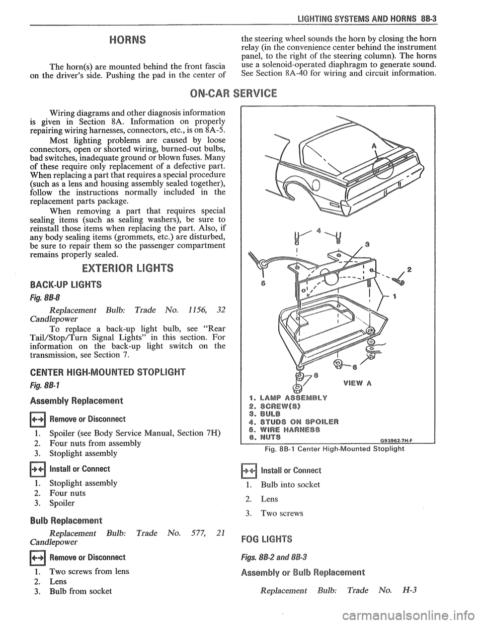
CENTER HIGH-MOUNTED STOPLIGHT
Fig. 8B-7
Assembly Replacement
Remove or Disconnect
1. Spoiler (see Body Service Manual, Section 7H)
2. Four nuts from assembly
3. Stoplight assembly
Install or Connect
1. Stoplight assembly
2. Four nuts
3. Spoiler
Bulb Replacement
Replacement Bulb: Trade No. 577, 21
Candlepo wer
Remove or Disconnect
1. Two screws from lens
2. Lens
3. Bulb from socket
1. LAMP ASSEMBLY
2. SCREW($) 3. BULB
4. STUD8 ON SPOILER 5. WIRE HARNESS
Fig. 8B-1 Center High-Mounted Stoplight
Install or Corrnect
1. Bulb into socket
2. Lens
3. Two screws
FOG LIGHTS
Figs. 8B-2 and 88-3
Assembly or Bulb Replacement
Replacement Bulb: Trade No. H-3
Page 1614 of 1825
INSTRUMENT PANEL. GAGES & CONSOLE 8C-3
tank only when ignition switch is turned to "ON" or
"ACCESSORY" positions.
When ignition is turned to "OFF" or "START"
positions, the pointer may come to rest at any position.
The letters
"E" and "F" on the fuel gage are used to
point out direction of indicator travel only.
TEMPERATURE WARNING LIGHT
The engine temperature warning light is
controlled by a thermal switch which senses engine
coolant temperatures.
When the ignition switch is turned to "START"
position, a test circuit is closed and the light will come
on to indicate whether the light is functioning properly.
It is important to note that with low boiling-point
coolants (such as plain water) the temperature light
may not come on even though the coolant is boiling.
GENERATOR WARNING LIGHT
The generator warning light, located in the
instrument cluster, should come on when the ignition
switch is turned
"ON" and engine is not running. If
not, either the bulb is burned out or wiring to generator
has an open circuit.
When the generator voltage output becomes
greater than the battery voltage, the
"GEN" light
should go out. This does not, however, indicate
whether the battery is being charged or if the voltage
regulator is functioning properly.
Checks of the charging system are covered in
Section 6D, 'Engine Electrical'.
ENGINE OIL PRESSURE LIGHT
The engine oil pressure warning light is mounted
in the instrument cluster and controlled by a pressure
operated switch located on the engine block. When the ignition switch is
in the
"run" or "start9' position, the
oil pressure light should come on. If not, the bulb is
burned out, there is an open circuit between the bulb
and the oil pressure switch, or there is an open circuit
between the oil pressure switch and the choke heater.
After the engine is running, the oil pressure light
should go out when the oil pressure reaches the correct
specification. If not an oil pressure problem, a faulty oil
pressure switch or an open circuit from the choke
heater fuse to the oil pressure switch is indicated.
"SERVICE ENGINE SOON" LIGHT
All cars have a "SERVICE ENGINE SOON"
light mounted in the instrument cluster. The
"SERVICE ENGINE SOON9' light should come on
during engine starting. The light may stay on
a short
time after the engine starts.
If the light comes on while
driving, service to the emission control system may be
required. See Section
6E and Section 8A-80,
'Instrument Cluster', for complete diagnosis and
wiring diagrams of the
""P;RVICE ENGINE SOON"
light circuit.
UPSHIFT INDICATOR LIGHT
If your vehicle has a manual transmission, there
may be an
''Upshift" light on the instrument panel.
This light is illuminated to indicate optimum shift
points throughout the range from optimum fuel
economy to optimum performance. When this light is
on, shift your transmission to the next higher gear
range if conditions permit. For fuel economy,
accelerate slowly and shift when the light goes on. For
performance, accelerate as desired and shift when the
light goes on.
Safe operation of the vehicle may require shifting
differently than indicated by the "Upshift" light to
adapt to weather, road or traffic conditions.
Downshifting one or more gears may be required
to keep the engine running smoothly or to maintain
satisfactory performance.
DIAGNOSIS
Diagnostic information for all instrument panel
electrical systems is found in Section
8A-80,
'Instrument Panel'.
CAUTION: When removing or
installing any electrical units,
disconnect the negative battery cable
to prevent possible short circuits
which could lead to personal injury
and/or property damage. When
replacing a speedometer or
odometer assembly, the law requires the
odometer reading of the replacement unit to
be set to register the same mileage as the
prior odometer.
if the same mileage cannot be
set, the
law requires that the replacement
odometer be set to zero and a label be
installed on the driver's door frame to show
the previous odometer reading and the date
of replacement.
GENERAL BNFORMATlOM
INSTRUMENT PANEL AND GAGES
The instrument panel is a single unit design and
and screws. To service the instrument panel and
all parts attach to the main instrument panel with clips components see Figs. 601 through 610.
Page 1629 of 1825
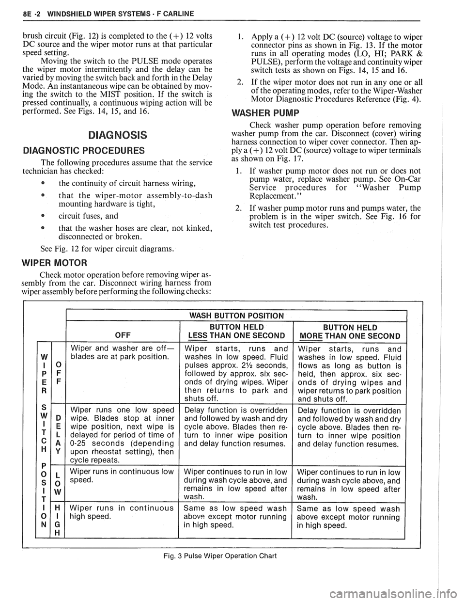
8E -2 WINDSHIELD WIPER SYSTEMS F CARLINE
brush circuit (Fig. 12) is completed to the (+) 12 volts
DC source and the wiper motor runs at that particular
speed setting.
Moving the switch to the PULSE mode operates
the wiper motor intermittently and the delay can be
varied by moving the switch back and forth in the Delay
Mode. An instantaneous wipe can be obtained by mov-
ing the switch to the MIST position. If the switch is
pressed continually, a continuous wiping action will be
performed. See Figs. 14,
15, and 16.
DIAGNOSVC PROCEDURES
The following procedures assume that the service
technician has checked:
@ the continuity of circuit harness wiring,
@ that the wiper-motor assembly-to-dash
mounting hardware is tight,
circuit fuses, and
@ that the washer hoses are clear, not kinked,
disconnected or broken.
1. Apply a (+) 12 volt DC (source) voltage to wiper
connector pins as shown in Fig. 13. If the motor
runs in all operating modes
(LO, HI; PARK &
PULSE), perform the voltage and continuity wiper
switch tests as shown on Figs. 14, 15 and 16.
2. If the wiper motor does not run in any one or all
of the operating modes, refer to the Wiper-Washer
Motor Diagnostic Procedures Reference (Fig.
4).
WASHER PUMP
Check washer pump operation before removing
washer pump from the car. Disconnect (cover) wiring
harness connection to wiper cover connector. Then ap-
ply a
(+) 12 volt DC (source) voltage to wiper terminals
as shown on Fig. 17.
1. If washer pump motor does not run or does not
pump water, replace washer pump, See On-Car
Service procedures for "Washer Pump
Replacement.
' '
2. If washer pump motor runs and pumps water, the
problem is in the wiper switch. See Fig. 16 for
switch test procedures.
See Fig. 12 for wiper circuit diagrams.
WIPER MOTOR
Check motor operation before removing wiper as-
sembly from the car. Disconnect wiring harness from
wiper assembly before performing the following checks:
Fig. 3 Pulse Wiper Operation Chart