width PONTIAC FIERO 1988 Service Repair Manual
[x] Cancel search | Manufacturer: PONTIAC, Model Year: 1988, Model line: FIERO, Model: PONTIAC FIERO 1988Pages: 1825, PDF Size: 99.44 MB
Page 233 of 1825
3E.2 TIRES AND WHEELS
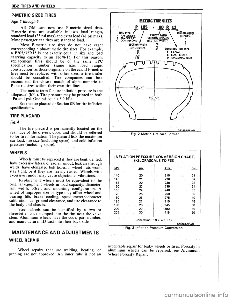
P-METRIC SIZED TIRES
Figs. 1 through 4
All GM cars now use P-metric sized tires.
P-metric tires are available in two load ranges,
standard load
(35 psi max) and extra load (41 psi max).
Most passenger car tires are standard load.
Most P-metric tire sizes do not have exact
corresponding alpha-numeric tire sizes. For example,
a
P205/75R15 is not exactly equal in size and load
carrying capacity to an
FR78-15. For this reason,
replacement tires should be of the same TPC
specification number (same size, load range,
construction) as those originally on the car. If P-metric
tires must be replaced with other sizes, a tire dealer
should be consulted. Tire companies can best
recommend the closest match of alpha-numeric to
P-metric sizes within their own tire lines.
The metric term for tire inflation pressure is the
kilopascal
(kPa). Tire pressure may be printed in both
kPa and psi. One psi equals 6.9 kPa.
See the tire placard or Section OB for tire inflation
specifications.
TlRE PLACARD
Fig. 4
The tire placard is permanently located on the
rear
face of the driver's door, and should be referred
to for tire information. The placard lists the maximum
car load, tire size (including spare), and cold inflation
pressure (including spare).
WHEELS
Wheels must be replaced if they are bent, dented,
have excessive lateral or radial
runout, leak air through
welds, have elongated bolt holes, if wheel nuts won't
stay tight, or if they are heavily rusted. Wheels with
excessive
runout may cause objectional vibrations.
Replacement wheels must be equivalent to the
original equipment wheels in load capacity, diameter,
rim width, offset, and mounting configuration.
A
wheel of improper size or type may affect wheel and
bearing life, brake cooling,
speedometer/odometer
calibration, car ground clearance, and tire clearance to
the body and chassis.
Steel wheels can be identified by a two or
three-letter code stamped into the rim near the valve
stem. Aluminum wheels have the code, part number,
and manufacturer
ID cast into their back side.
MAINTENANCE AND ADJUSTMENTS
WHEEL REPAIR
Wheel repairs that use welding, heating, or
peening are not approved. An inner tube is not an
Fig. 2 Metric Tire Size Format
INFLATION PRESSURE CONVERSION CHART (KI LOPASCALS TO PSI)
Fig. 3 Inflation Pressure Conversion
acceptable repair for leaky wheels or tires. Porosity in
aluminum wheels can be repaired, see Aluminum
Wheel Porosity Repair.
Page 262 of 1825
REAR AXLE 481-9
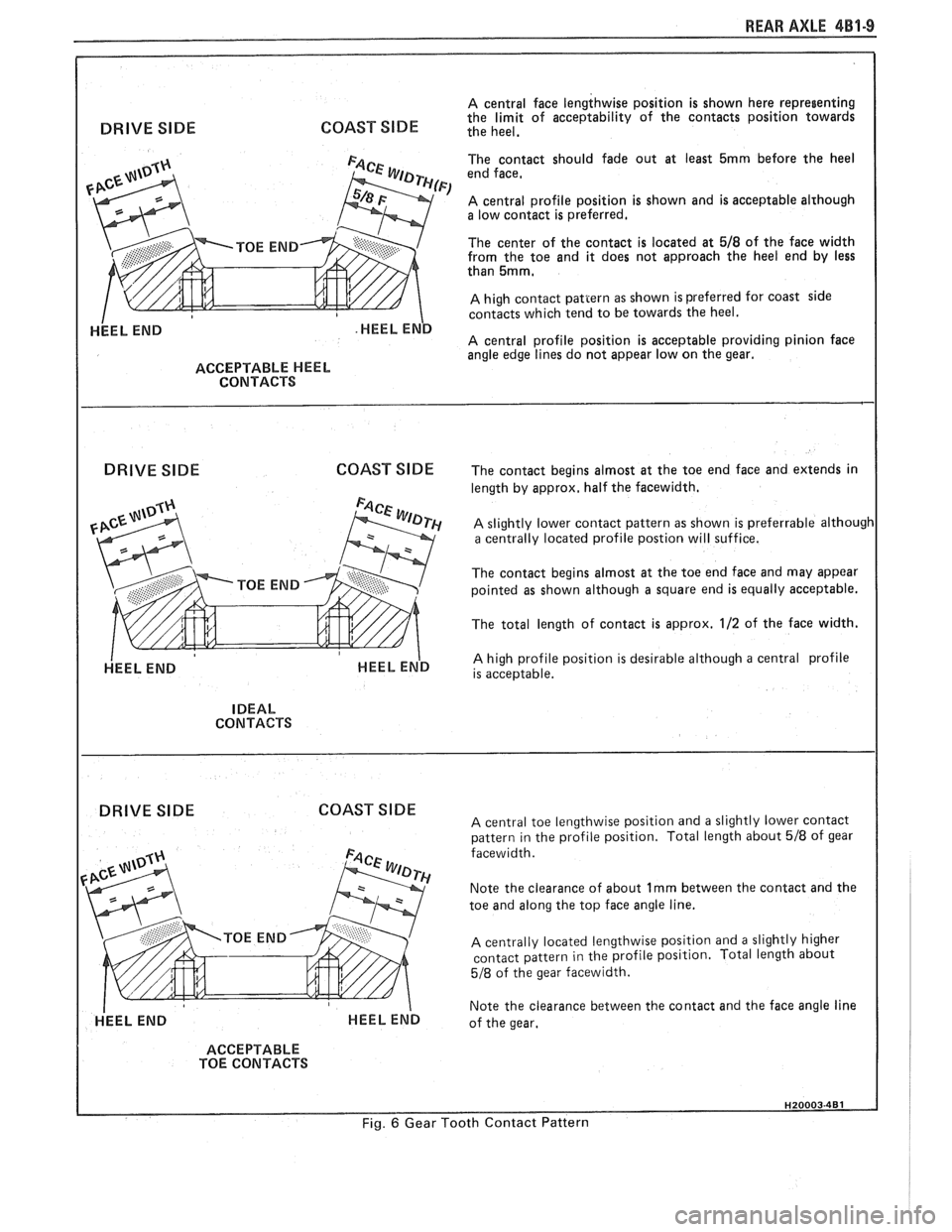
A central face lengthwise position is shown here representing
COAST SlDE the limit of acceptability of the contacts position towards DRIVE SIDE the heel.
ACCEPTABLE HEEL
CONTACTS
DRIVE SlDE COAST
SlDE
HEEL END
The contact should fade out at least 5mrn before the heel
end face,
A central profile position is shown and is acceptable alrhough a low contact is preferred.
The center of the contact is located at
518 of the face width
from the toe and it does not approach the heel end by less
than
5mm,
A high contact pattern as shown is preferred for coast side
contacts which tend to be towards the heel.
A central profile position is acceptable providing pinion face
angle edge lines do not appear low on the gear.
The contact begins almost at the toe end face and extends in
length by approx, half the facewidth.
A slightly lower contact pattern as shown is preferrable although a centrally located profile postion will suffice.
The contact begins almost at the toe end face and may appear
pointed as shown although a square end is equally acceptable.
The total length of contact is approx.
112 of the face width.
A high profile position is desirable although a central profile
is acceptable.
IDEAL
CONTACTS
DRIVE SIDE COAST SIDE A central toe lengthwise position and a slightly lower contact
pattern in the profile position. Total length about 518 of gear
facewidth.
Note the clearance of about
1 rnrn between the contact and the
toe and along the top face angle line.
A centrally located lengthwise position and a slightly higher
contact pattern in the profile position. Total length about
518 of the gear facewidth.
Note the clearance between the contact and the face angle line
of the gear.
ACCEPTABLE
TOE CONTACTS
Fig. 6 Gear Tooth Contact Pattern
Page 370 of 1825
2.8 LITER V-6 6A2-19
4. Measure the crankpin for out-of-round or taper
with a micrometer. If not within specifications,
replace or recondition the crankshaft. If within
specifications and a new bearing is to be installed,
measure the maximum diameter of the crankpin,
to determine new bearing size required.
5. If within specifications, measure new or used
bearing clearance with Plastigage or its
equivalent.
NOTICE: If a bearing is being fitted to an
out-of-round crankpin, be sure to fit to the
maximum diameter of the crankpin. If the bearing
is fitted to the minimum diameter and the
crankpin is out-of-round .025mm interference
between the bearing and
crankpin will result in a
rapid bearing failure.
a.
Place a piece of gaging plastic the full width
of the
crankpin as contacted by the bearing
(parallel to the crankshaft).
b. Install
the bearing in the connecting rod and
cap.
c. Install
the rod cap and evenly torque nuts
to specifications. Do not turn the crankshaft
with gaging plastic installed.
d. Remove
the rod cap and using the scale on
the gaging plastic envelope, measure the
gaging plastic width at the widest point.
6. If
the clearance exceeds specifications, select a
new, correct size, bearing and remeasure the
clearance.
If clearance cannot be brought to within
specifications, the
crankpin will have to be
ground undersize. If the
crankpin is already
at maximum undersize, replace crankshaft.
7. Coat the
bearing surface with oil, install the rod
cap and torque nuts to 50
N-m (37 lb. ft.).
8. When all connecting rod bearings have been
installed tap each rod lightly (parallel to the
crankpin) to make sure they have clearance.
9. Measure all connecting rod side clearances (see
specifications) between the rod cap and
crankshaft throw (Figure 6A2-23).
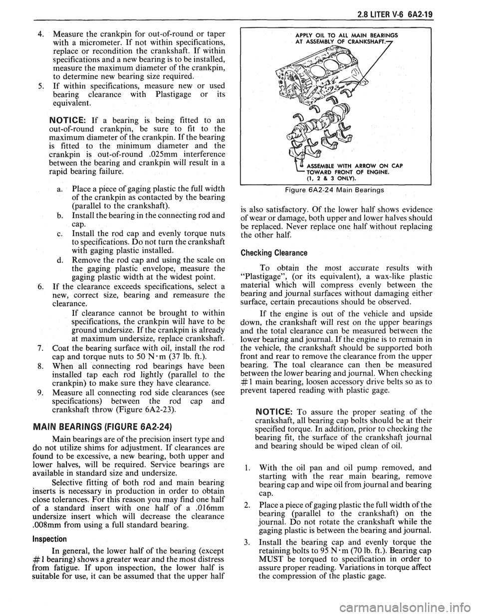
MAIN BEARINGS (FIGURE 6A2-24)
Main bearings are of the precision insert type and
do not utilize shims for adjustment. If clearances are
found to be excessive, a new bearing, both upper and
lower halves, will be required. Service bearings are
available in standard size and undersize.
Selective fitting of both rod and main bearing
inserts is necessary in production in order to obtain
close tolerances. For this reason you may find one half
of a standard insert with one half of a
.016mm
undersize insert which will decrease the clearance
.008mm from using a full standard bearing.
Inspection
In general, the lower half of the bearing (except
# 1 bearing) shows a greater wear and the most distress
from fatigue. If upon inspection, the lower half is
suitable for use, it can be assumed that the upper half
APPLY OIL TO ALL MAlN BEARINGS
E WITH ARROW ON CAP
FRONT OF ENGINE.
(1, 2 8, 3 ONLY).
Figure 6A2-24 Main Bearings
is also satisfactory. Of the lower half shows evidence
of wear or damage, both upper and lower halves should
be replaced. Never replace one half without replacing
the other half.
Checking Clearance
To obtain the most accurate results with
"Plastigage", (or its equivalent), a wax-like plastic
material which will compress evenly between the
bearing and journal surfaces without damaging either
surface, certain precautions should be observed.
If the engine is out of the vehicle and upside
down, the crankshaft will rest on the upper bearings
and the total clearance can be measured between the
lower bearing and journal. If the engine is to remain in
the vehicle, the crankshaft should be supported both
front and rear to remove the clearance from the upper
bearing. The toal clearance can then be measured
between the lower bearing and journal. When checking
# 1 main bearing, loosen accessory drive belts so as to
prevent tapered reading with plastic gage.
NOTICE: To assure the proper seating of the
crankshaft, all bearing cap bolts should be at their
specified torque. In addition, prior to checking the
bearing fit, the surface of the crankshaft journal
and bearing should be wiped clean of oil.
1. With the oil pan and oil pump removed, and
starting with the rear main bearing, remove
bearing cap and wipe oil from journal and bearing
cap.
2. Place a piece of gaging plastic the full width of the
bearing (parallel to the crankshaft) on the
journal. Do not rotate the crankshaft while the
gaging plastic is between the bearing and journal.
3. Install
the bearing cap and evenly torque the
retaining bolts to 95
N.m (70 lb. ft.). Bearing cap
MUST be torqued to specification in order to
assure proper reading. Variations in torque affect
the compression of the plastic gage.
Page 371 of 1825
4. Remove bearing cap. The flattened gaging plastic
will be found adhering to either the bearing shell
or journal.
5. On the edge of gaging plastic envelope, there is a
graduated scale which is correlated in
thousandths of a millimetre. Without removing
the gaging plastic, measure its compressed width
(at the widest point) with the graduations on the
gaging plastic envelope. Normally, main bearing
journals wear evenly and are not out-of-round.
However, if
a bearing is being fitted to an
out-of-round (.025mm max.), be sure to fit to the
maximum diameter of the journal: If the bearing
is fitted to the minimum diameter and the journal
is out-of-round
.025mm, interference between the
bearing and journal will result in rapid bearing
failure. If the flattened gaging plastic tapers
toward the middle or ends, there is a difference
in clearance indicating taper, low spot or other
irregularity of the bearing or journal. Be sure to
measure the journal with a micrometer if the
flattened gaging plastic indicates more than
,025mm difference.
6. If the bearing clearance is within specifications,
the bearing insert is satisfactory. If the clearance
is not within specifications, replace the insert.
Always replace both upper and lower inserts as
a unit.
7. A standard,
.016mm and .032mm undersize
bearing may produce the proper clearance. If not,
it will be necessary to regrind the crankshaft
journal for use with the next undersize bearing.
After selecting new bearing, recheck clearance.
8. Proceed to the next bearing. After all bearings
have been checked rotate the crankshaft to see
that there is no excessive drag.
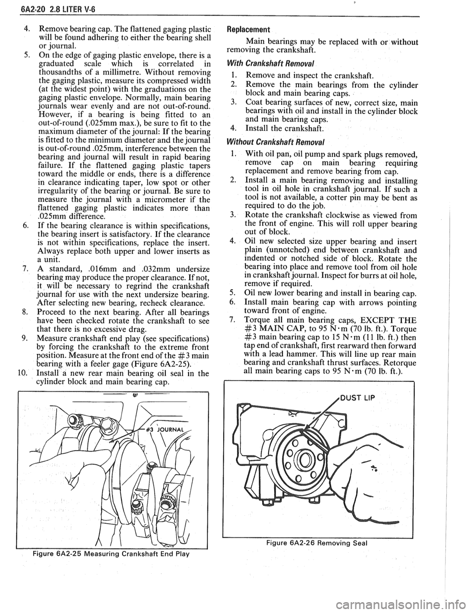
9. Measure crankshaft end play (see specifications)
by forcing the crankshaft to the extreme front
position. Measure at the front end of the
#3 main
bearing with a feeler gage (Figure 6A2-25).
10. Install a new rear main bearing oil seal in the
cylinder block and main bearing cap.
Figure 6A2-25 Measuring Crankshaft End Play
Replacement
Main bearings may be replaced with or without
removing the crankshaft.
With Crankshaft Removal
1. Remove and inspect the crankshaft.
2. Remove the main bearings from the cylinder
block and main bearing caps.
3. Coat bearing surfaces of new, correct size, main
bearings with oil and install in the cylinder block
and main bearing caps.
4. Install the crankshaft.
Without Crankshaft Removal
With oil pan, oil pump and spark plugs removed,
remove cap on main bearing requiring
replacement and remove bearing from cap.
Install a main bearing removing and installing
tool in oil hole in crankshaft journal. If such a
tool is not available, a cotter pin may be bent as
required to do the job.
Rotate the crankshaft clockwise as viewed from
the front of engine. This will roll upper bearing
out of block.
Oil new selected size upper bearing and insert
plain (unnotched) end between crankshaft and
indented or notched side of block. Rotate the
bearing into place and remove tool from oil hole
in crankshaft journal. Inspect for burrs at oil hole,
remove if required.
Oil new lower bearing and install in bearing cap.
Install main bearing cap with arrows pointing
toward front of engine.
Torque all main bearing caps, EXCEPT THE
#3 MAIN CAP, to 95 N.m (70 lb. ft.). Torque
# 3 main bearing cap to 15 N m (1 1 lb. ft.) then
tap end of crankshaft, first rearward then forward
with a lead hammer. This will line up rear main
bearing and crankshaft thrust surfaces.
Retorque
all main bearing caps to 95 N.m (70 Ib. ft.).
1 /DUST LIP
Figure 6A2-26 Removing Seal
Page 375 of 1825
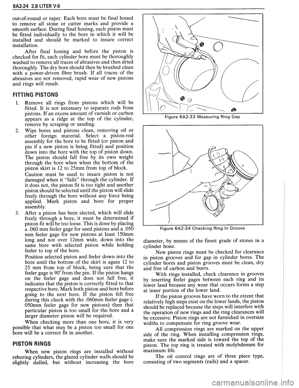
6A2-24 2.8 LITER V-6
out-of-round or taper. Each bore must be final honed
to remove all stone or cutter marks and provide a
smooth surface. During final honing, each piston must
be fitted individually to the bore in which it will be
installed and should be marked to insure correct
installation.
After final honing and before the piston is
checked for fit, each cylinder bore must be thoroughly
washed to remove all traces of abrasives and then dried
thoroughly. The dry bore should then be brushed clean
with a power-driven fibre brush. If all traces of the
abrasives are not removed, rapid wear of new pistons
and rings will result.
FITTING PISTONS
1. Remove all rings
from pistons which will be
fitted. It is not necessary to separate rods from
pistons. If an excess amount of varnish or carbon
appears as a ridge at the top of the cylinder,
remove by scraping or sanding.
2. Wipe bores
and pistons clean, removing oil or
other foreign material. Select a piston-rod
assembly for the bore to be fitted (or piston and
pin if a new piston is being fitted) and position
down into the bore with the top of piston down.
The piston should fall free by its own weight
through the bore when when the bottom of the
piston skirt is 12 to 25mm from top of block.
Caution must be used to insure piston is not
damaged when it "falls" through the cylinder. If
it does not, the piston fit is too tight and another
piston should be selected until the piston will slide
freely through the bore without any force being
applied. Mark piston and bore for proper
assembly.
3. After a piston has been slected, which will slide
freely through a bore, it must be determined if
piston fit will be too loose. This is done by placing
a ,060 mm feeler gage for used pistons and a
.050
mm feeler gage for new pistons at least 150mm
long and not over 12mm wide, down into the
same bore with selected piston while holding
feeler to top of the bore.
Position selected piston and feeler down into the
bore until the bottom of the skirt is again 12 to
25 mm from top of block, being sure that the
feeler gage is
90" from the pin. If the piston hangs
on the feeler gage and does not fall free, it
indicates that the piston is correctly fitted to that
respective bore. Mark both piston and bore before
going to the next bore. If the piston fell free
during this check with the
.060mm feeler gage (.
050mm feeler gage for new pistons) then that
particular piston is too small for the bore and a
larger diameter piston will be required.
When checking more than one bore, it is very
possible that what may be a piston too small for one
bore will be a correct fit in another.
PISTON RINGS
When new piston rings are installed without
reboring cylinders, the glazed cylinder walls should be
slightly dulled, but without increasing the bore
I I Figure 6A2-33 Measuring Ring Gap
i I
I I Figure 6A2-34 Checking Ring In Groove
diameter, by means of the finest grade of stones in a
cylinder hone.
New piston rings must be checked for clearance
in piston grooves and for gap in cylinder bores. The
cylinder bores and piston grooves must be clean, dry
and free of carbon and burrs.
With rings installed, check clearance in grooves
by inserting feeler gages between each ring and its
lower land because any wear that occurs forms a step
at inner portion of the lower land.
If the piston grooves have worn to the extent that
relatively high steps exist on the lower lands, the piston
should be replaced because the steps will interfere with
the operation of new rings and the ring clearances will
be excessive. Piston rings are not furnished in oversize
widths to compensate for ring groove wear.
All compression rings are marked on the upper
side of the ring. When installing compression rings,
make sure the marked side is toward the top of the
piston. The top ring is treated with molybdenum for
maximum life.
The oil control rings are of three piece type,
consisting of two segments (rails) and a spacer.
Page 378 of 1825
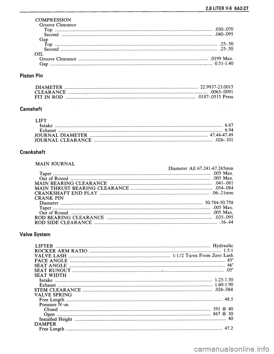
COMPRESSION Groove Clearance
............................................................................................................................ Top .030..070
................................................................................ Second .................................... .... .040.. 095
Gap ................................................................................................................................. Top .25..50
............................................................................................................................ Second .25..50
OIL
...................................................................................................... . Groove Clearance 0 199 Max
Gap
................................................................................................................................ 0.51-1.40
Piston Pin
DIAMETER ....................................................................................................... 22.9937-23.0015
........................................................................................................... CLEARANCE .0065-.009 1
FIT IN ROD
..................................................................................................... .0187-. 0515 Press
Camshaft
LIFT
Intake
................................................................................................................................... 6.67
Exhaust
.................................................................................................................................. 6.94
............................................................. ............................ JOURNAL DIAMETER .. 47.44-47.49
............................................................................................. JOURNAL CLEARANCE .026- . 101
Crankshaft
MAIN JOURNAL
Diameter All
67.241-67.265mm
............................................................................................................................. Taper 005 Max .
................................................................................................................ Out of Round 005
Max .
.................................................................................. MAIN BEARING CLEARANCE 04
1-.08 1
................................................................ MAIN THRUST BEARING CLEARANCE .054..084
...................................................................................... CRANKSHAFT END PLAY .06-. 2 1mm
CRANK PIN
Diameter
..................................... ... ......................................................................... 50.784-50.758
............................................................................................................................. Taper 005 Max .
............................................................................................................ Out of Round 005
Max .
.................................................... ROD BEARING CLEARANCE ......................... .. 03 5..095
................................................................................................ ROD SIDE CLEARANCE .16-. 44
Valve System
LIFTER ......................... .. ........................................................................................... Hydraulic
......................................................................................................... ROCKER ARM RATIO 1.5. 1
............................................................................... VALVE LASH 1- 1/2 Turns From Zero Lash
FACE ANGLE
........................................................................................................................... 45"
SEAT ANGLE ......................................................................................................................... 46"
....................................................................................................................... SEAT RUNOUT 05"
SEAT WIDTH
Intake
........................................................................................................................ 1.25-1.50
......................................................................................................................... Exhaust 1.60- 1.90
............................................................... STEM CLEARANCE ..................................... ... .026-. 068
VALVE SPRING
Free Length
......................................................................................................................... 48.5
Pressure N
. m
Closed
....................... .. .......................................................................................... 391 @40
Open
......................................................................................................................... 867 @30
Installed Height
........................................................................................................................ 40
DAMPER
........................................................................................................................... Free Length 47.2
Page 399 of 1825
6A3-20 V-8 ENGINE
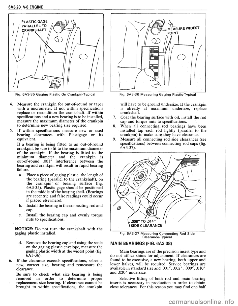
PLASTIC GAGE
Fig. 6A3-35 Gaging Plastic On Crankpin-Typical
4. Measure the crankpin for out-of-round or taper
with a micrometer. If not within specifications
replace or recondition the crankshaft. If within
specifications and a new bearing is to be installed,
measure the maximum diameter of the
crankpin
to determine new bearing size required.
5. If within specifications measure new or used
bearing clearances with Plastigage or its
equivalent.
If a bearing is being fitted to an out-of-round
crankpin, be sure to fit to the maximum diameter
of the crankpin. If the bearing is fitted to the
minimum diameter and the
crankpin is
out-of-round .OO 1
" interference between the
bearing and
crankpin will result in rapid bearing
failure.
a. Place a piece of gaging plastic, the length of
the bearing (parallel to the crankshaft), on
the
crankpin or bearing surface (fig.
6A3-35). Plastic gage should be positioned
in the middle of the bearing shell. (Bearings
are eccentric and false readings could occur
if placed elsewhere).
b. Install the bearing in the connecting rod and
cap.
c. Install the bearing cap and evenly torque
nuts to specifications.
NOTICE: Do not turn the crankshaft with the
gaging plastic installed.
d. Remove the bearing cap and using the scale
on the gaging plastic envelope, measure the
gaging plastic width at the widest point (fig.
6A3-36).
6. If the clearance exceeds specifications, select a
new, correct size, bearing and remeasure the
clearance.
Be sure to check what size bearing is being
removed in order to determine proper
replacement size bearing. If clearance cannot be
brought to within specifications, the
crankpin
Fig. 6A3-36 Measuring Gaging Plastic-Typical
will have to be ground undersize. If the crankpin
is already at maximum undersize, replace
crankshaft.
7. Coat the bearing surface with oil, install the rod
cap and torque nuts to specifications.
8. When all connecting rod bearings have been
installed tap each rod lightly (parallel to the
crankpin) to make sure they have clearance.
9. Measure all connecting rod side clearances (see
specifications) between connecting rod caps (fig.
6A3-37).
..WS1'TQ.014" 1
s
/
SIDE CLEARANCE
Fig.
6A3-37 Measuring Connecting Rod Side
Clearance-Typical
MAIN BEARINGS (FIG. 8A3-38)
Main bearings are of the precision insert type and
do not utilize shims for adjustment. If clearances are
found to be excessive, a new bearing, both upper and
lower halves, will be required. Service bearings are
available in standard size and
,001 ", .002", .009", .01OV
and .020" undersize.
Selective fitting of both rod and main bearing
inserts is necessary in production in order to obtain
close tolerances. For this reason you may find one half
Page 400 of 1825
V-8 ENGINE 6A3-21
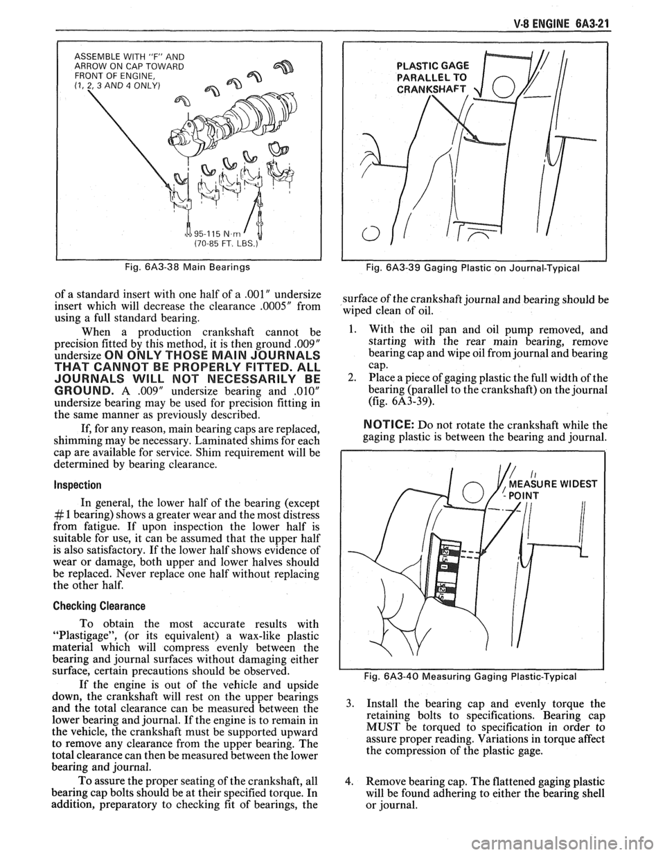
ASSEMBLE WITH 'IF" AND
ARROW ON CAP TOWARD
FRONT OF ENGINE,
(1, 2, 3 AND 4 ONLY)
h a 95-1 15 N.m I t (70-85 FT. LBS.)
Fig. 6A3-38 Main Bearings
of a standard insert with one half of a .00lU undersize
insert which will decrease the clearance
.0005" from
using a full standard bearing.
When a production crankshaft cannot be
precision fitted by this method, it is then ground
.00$"
undersize ON ONLY THOSE MAIN JOURNALS
THAT CANNOT BE PROPERLY FITTED. ALL
JOURNALS
WILL MOT NECESSARILY BE
GROUND.
A .009" undersize bearing and ,010"
undersize bearing may be used for precision fitting in
the same manner as previously described.
If, for any reason, main bearing caps are replaced,
shimming may be necessary. Laminated shims for each
cap are available for service. Shim requirement will be
determined by bearing clearance.
Inspection
In general, the lower half of the bearing (except
# 1 bearing) shows a greater wear and the most distress
from fatigue. If upon inspection the lower half is
suitable for use, it can be assumed that the upper half
is also satisfactory. If the lower half shows evidence of
wear or damage, both upper and lower halves should
be replaced. Never replace one half without replacing
the other half.
Checking Clearance
To obtain the most accurate results with
"Plastigage", (or its equivalent) a wax-like plastic
material which will compress evenly between the
bearing and journal surfaces without damaging either
surface, certain precautions should be observed.
If the engine is out of the vehicle and upside
down, the crankshaft will rest on the upper bearings
and the total clearance can be measured between the
lower bearing and journal. If the engine is to remain in
the vehicle, the crankshaft must be supported upward
to remove any clearance from the upper bearing. The
total clearance can then be measured between the lower
bearing and journal.
To assure the proper seating of the crankshaft, all
bearing cap bolts should be at their specified torque. In
addition, preparatory to checking fit of bearings, the
Fig. 6A3-39 Gaging Plastic on Journal-Typical
surface of the crankshaft journal and bearing should be
wiped clean of oil.
1. With the oil pan and oil pump removed, and
starting with the rear main bearing, remove
bearing cap and wipe oil from journal and bearing
cap.
2. Place a piece of gaging plastic the full width of the
bearing (parallel to the crankshaft) on the journal
(fig. 6A3-39).
NOTICE: Do not rotate the crankshaft while the
gaging plastic is between the bearing and journal.
Fig. 6A3-40 Measuring Gaging Plastic-Typical
3. Install the bearing cap and evenly torque the
retaining bolts to specifications. Bearing cap
MUST be torqued to specification in order to
assure proper reading. Variations in torque affect
the compression of the plastic gage.
4. Remove bearing cap. The flattened gaging plastic
will be found adhering to either the bearing shell
or journal.
Page 401 of 1825
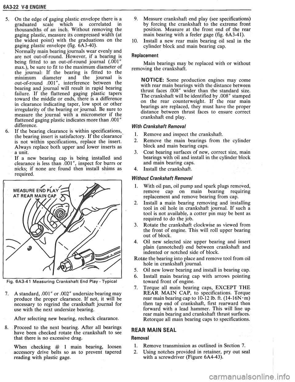
BA3-22 V-8 ENGINE
5. On the edge of gaging plastic envelope there is a
graduated scale which is correlated in
thousandths of an inch. Without removing the
gaging plastic, measure its compressed width (at
the widest point) with the graduations on the
gaging plastic envelope (fig. 6A3-40).
Normally main bearing journals wear evenly and
are not out-of-round. However, if a bearing is
being fitted to an out-of-round journal
(.00lU
max.), be sure to fit to the maximum diameter of
the journal: If the bearing is fitted to the
minimum diameter and the journal is
out-of-round
.001", interference between the
bearing and journal will result in rapid bearing
failure. If the flattened gaging plastic tapers
toward the middle or ends, there is a difference
in clearance indicating taper, low spot or other
irregularity of the bearing or journal. Be sure to
measure the journal with a micrometer if the
flattened gaging plastic indicates more than
.00lV
difference.
6. If the bearing clearance is within specifications,
the bearing insert is satisfactory. If the clearance'
is not within specifications, replace the insert.
Always replace both upper and lower inserts as
a unit.
If a new bearing cap is being installed and
clearance is less than
.00 1 ", inspect for burrs or
nicks; if none are found then install shims as
required.
I MEASURE END PLAY
Fig. 6A3-4 1 Measuring Crankshaft End Play - Typical
7. A standard, .001" or .002" undersize bearing may
produce the proper clearance. If not, it will be
necessary to regrind the crankshaft journal for
use with the next undersize bearing.
After selecting new bearing, recheck clearance.
8. Proceed to the next bearing. After all bearings
have been checked rotate the crankshaft to see
that there is no excessive drag.
When checking
&t 1 main bearing, loosen
accessory drive belts so as to prevent tapered
reading with plastic gage.
9. Measure crankshaft end play (see specifications)
by forcing the crankshaft to the extreme front
position. Measure at the front end of the rear
main bearing with a feeler gage (fig.
61\3-41),
10. Install a new rear main bearing oil seal in the
cylinder block and main bearing cap.
Replacement
Main bearings may be replaced with or without
removing the crankshaft.
NOTICE: Some production engines may come
with rear main bearings with the distance between
thrust faces
,008" wider than the standard size.
The crankshaft will be identified by
,008" stamped
on the rear counterweight. If the rear main
bearings are replaced, they must have the proper
distance between thrust faces to ensure correct
crankshaft end play.
With Crankshaft Removal
1. Remove and inspect the crankshaft.
2. Remove the main bearings from the cylinder
block and main bearing caps.
3. Coat bearing surfaces of new, correct size, main
bearings with oil and install in the cylinder block
and main bearing caps.
4. Install the crankshaft.
Without Crankshaft Removal
1. With oil pan, oil pump and spark plugs removed,
remove cap on main bearing requiring
replacement and remove bearing from cap.
2. Install a
main bearing removing and installing
tool in oil hole in crankshaft journal. If such a
tool is not available, a cotter pin may be bent as
required to do the job.
3. Rotate the crankshaft clockwise as viewed from
the front of engine. This will roll upper bearing
out of block.
4. Oil new selected size upper bearing and insert
plain (unnotched) end between crankshaft and
indented or notched side of block.
Rot$e the bearing into place and remove tool from oil
hole in crankshaft journal.
5. Oil new lower bearing and install in bearing cap.
6. Install main bearing cap with arrows pointing
toward front of engine.
7. Torque all main bearing caps, EXCEPT THE
REAR MAIN CAP, to specifications. Torque
rear main bearing cap to 10- 12 lb. ft. (14-
16N. m)
then tap end of crankshaft, first rearward then
forward with a lead hammer. This will line up
rear main bearing and crankshaft thrust surfaces.
Retorque all main bearing caps to specifications.
REAR MAIN SEAL
Removal
1. Remove transmission as outlined in Section 7.
2. Using notches provided
in retainer, pry out seal
with a screwdriver (Figure 6A4-43).
Page 409 of 1825
6A3-30 V-8 ENGINE
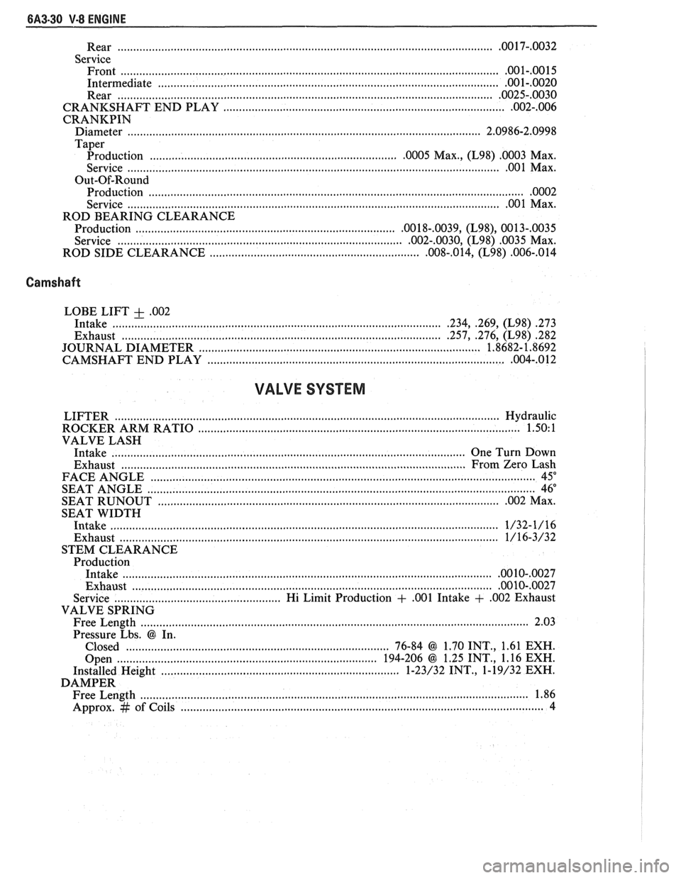
.............................................................................................. Rear ................... .. .OO 17-.0032
Service Front
......................................................................................................................... .001-.0015
Intermediate ............................................................................................................ .001-.0020
Rear ....................................................................................................................... .0025-.0030
............................................................. CRANKSHAFT END PLAY ....................... .. .002-.006
CRANKPIN
Diameter ........................... .. ................................................................................. 2.0986-2.0998
Taper
................................................ Production ....................... .. .0005 Max., (L98) .0003 Max.
............................................................................. Service ............................ .. ...... .... .OO 1 Max.
Out-Of-Round Production
....................................................................................................................... .0002
................................................................................... Service ............................ .. .00 1 Max.
ROD BEARING CLEARANCE
Production
................................................................................ ,0018-.0039, (L98), 0013-,0035
................................................... Service ................................. ....... .002-.0030, (L98) .0035 Max.
ROD SIDE CLEARANCE
............................................................... ,008-.014, (L98) .006-,014
Camshaft
LOBE LIFT + .002
Intake ..................... .. .......................................................................... .234, .269, (L98) .273
Exhaust ................................................................................................. .257, .276, (L98) 282
....................................................... JOURNAL DIAMETER .................... .... ... 1.8682- 1.8692
................................................................. CAMSHAFT END PLAY ...................... .. ,004-.012
VALVE SYSTEM
LIFTER ......................................................................................................................... Hydraulic
ROCKER ARM RATIO
................................................................................................. 1.50: 1
VALVE LASH
Intake
............................................................................................................. One Turn Down
Exhaust
..................................... ... ...................................................................... From Zero Lash
FACE ANGLE
..................... ... ............................................................................................. 45"
.......................................................................................................................... SEAT ANGLE 46"
SEAT
RUNOUT ............................................................................................................. .002 Max.
SEAT WIDTH
Intake
.................................... .... .................................................................................... 1/32-1/16
Exhaust ......................................................................................................................... 1/16-3/32
STEM CLEARANCE
Production
Intake
.................................................................................................................... .0010-,0027
Exhaust .................................................................................................................. .00 10-.0027
Service .................................................. Hi Limit Production + ,001 Intake + ,002 Exhaust
VALVE SPRING
Free Length
......................................................................................................................... 2.03
Pressure Lbs.
@ In.
Closed
.................................................................................... 76-84 @ 1.70 INT., 1.61 EXH.
Open
............................................................................... 194-206 @ 1.25 INT., 1.16 EXH.
Installed Height
....................... .. ............................................. 1-23/32 INT., 1-19/32 EXH.
DAMPER Free Length
................... .. ............................................................................................... 1.86
Approx.
# of Coils .................................................................................................................. 4