fuses PONTIAC FIERO 1988 Service Repair Manual
[x] Cancel search | Manufacturer: PONTIAC, Model Year: 1988, Model line: FIERO, Model: PONTIAC FIERO 1988Pages: 1825, PDF Size: 99.44 MB
Page 711 of 1825
6E3-B-2 2.8L (VIN 5) DRIVEABILITY AND EMISSIONS
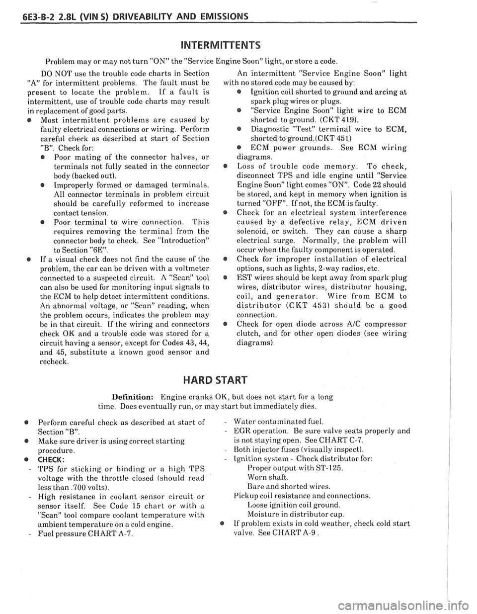
Problem may or may not turn "ON" the "Service Engine SoonJ' light, or store a code.
DO NOT use the trouble code charts in Section
"A" for intermittent problems. The fault must be
present to locate the problem. If a fault is
intermittent, use of trouble code charts may result
in replacement of good parts.
@ Most intermittent problems are caused by
faulty electrical connections or wiring. Perform
careful check as described at start of Section
"B". Check for:
@ Poor mating of the connector halves, or
terminals not fully seated in the connector
body (backed out).
@ Improperly formed or damaged terminals.
All connector terminals in problem circuit
should be carefully reformed to increase
contact tension.
@ Poor terminal to wire connection. This
requires removing the terminal from the
connector body to check. See "Introduction"
to Section
"6E".
@ If a visual check does not find the cause of the
problem, the car can be driven with a voltmeter
connected to a suspected circuit. A "Scan" tool
can also be used for monitoring input signals to
the ECM to help detect intermittent conditions.
An abnormal voltage, or "Scan" reading, when
the problem occurs, indicates the problem may
be in that circuit. If the wiring and connectors
check OK and a trouble code was stored for a
circuit having a sensor, except for Codes
43, 44,
and 45, substitute a known good sensor and
recheck. An
intermittent "Service Engine Soon" light
with no stored code may be caused by:
@ Ignition coil shorted to ground and arcing at
spark plug wires or plugs.
@ "Service Engine Soon" light wire to ECM
shorted to ground. (CKT 419).
@ Diagnostic "Test" terminal wire to ECM,
shorted to
ground.(CKT 451)
@ ECM power grounds. See ECM wiring
diagrams.
@ Loss of trouble code memory. To check,
disconnect TPS and idle engine until "Service
Engine Soon" light comes "ON". Code
22 should
be stored, and kept in memory when ignition is
turned "OFF". If not, the ECM is faulty.
@ Check for an electrical system interference
caused by a defective relay, ECM driven
solenoid, or switch. They can cause
a sharp
electrical surge. Normally, the problem will
occur when the faulty component is operated.
@ Check for improper installation of electrical
options, such as lights, 2-way radios, etc.
@ EST wires should be kept away from spark plug
wires, distributor wires, distributor housing,
coil, and generator. Wire from ECM to
distributor (CKT
453) should be a good
connection.
@ Check for open diode across A/C compressor
clutch, and for other open diodes (see wiring
diagrams).
HARD START
Definition: Engine cranks OK, but does not start for a long
time. Does eventually run, or may start hut immediately dies.
@ Perform careful check as described at start of -
Section "B".
@ Make sure driver is using correct starting
procedure.
@ CHECK:
- TPS for sticking or binding or a high TPS
voltage with the throttle closed (should read
less than
,700 volts).
- High resistance in coolant sensor circuit or
sensor itself. See Code 15 chart or with
a.
"Scan" tool compare coolant temperature with
ambient temperature on
a cold engine. 8
- Fuel pressure CHART A-7. Water contaminated
fuel.
EGR operation. Be sure valve seats properly and
is not staying open. See CHART C-7.
Both injector fuses (visually inspect).
Ignition system
- Check distributor for:
Proper output with ST-125.
Worn shaft.
Bare and shorted wires.
Pickup coil resistance and connections.
Loose ignition coil ground.
Moisture in distributor cap.
If problem exists in cold weather, check cold start
valve. See CHART A-9.
Page 817 of 1825

6E3-A-14 5.0L (VIN F) & 5.7L (VIN 8) DRIVEABILITY AND EMISSIONS
CHART A-3
(Page 1 of 2)
ENGINE CRANKS BUT WON'T RUN
5.OL (VIN F) & 5.7L (VIN 8) "F" SRIES (PORT)
Circuit Description :
This chart assumes that battery condition and engine cranking speed are OK, and there is adequate fuel in
the tank.
Test Description: Numbers below refer to circled Diagnostic Aids:
numbers on the diagnostic chart.
1. A "Service Engine Soon" light "ON" is a basic test @ An EGR valve sticking open can cause a low
to determine if there is a
12 volt supply and airlfuel ratio during cranking. Unless
engine
ignition
12 volts to ECM. No ALDL may be due to enters
"Clear Flood" at the first indication of a
an ECM problem and CHART
A-2 will diagnose flooding
condition, it can result in a no start.
the ECM. If TPS is over
2.5 volts the engine may @ Check for fouled plugs.
be in the clear flood mode which will cause
@ A defective cold start circuit or water in fuel line
starting problems. The engine
will not start can
cause a no start in cold weather. See
CHART
without reference pulses and therefore the "Scan" A-9.
should read rpm (reference) during crank. @ A defective MAF Sensor may cause a no start or a
2. No spark may be caused by one of several stall
after start. To determine if the sensor is
components related to the Ignition System. causing
the problem, disconnect it. The
ECM will
CHART C-4 will address all problems related to then
use a default value for the sensor, and if the
the causes of a no spark condition. condition
is corrected and the connections are
OK,
3. The test light should blink, indicating the ECM is replace the sensor.
controlling the injectors ok. How bright the light
@ rllso check that injectors on both sides of engine
blinks is not important. However, the test light
will cause a test light to "blink". If not OK, check
should be a
5-34730-3 or equivalent. injector fuses.
4. Use fuel
pressure gage 5-34730-1 or equivalent. If al~ove are all OK, refer to "Symptoms" it1
Wrap a shop towel around the fuel pressure tap to Scction "R". Ilard Start.
absorb any small amount of fuel leakage that may
occur when installing the gage.
Page 825 of 1825
6E3-A-22 5.OL (VIN F) & 5.7L (VIN 8) DRIVEABILITY AND EMISSIONS
COLD START SWITCH
CONNECTOR
CLOSED BELOW
3S°C.
8 SEC. TIME LIMIT
COOLANT
CHART A99
COLD START VALVE CIRCUIT TEST
5.OL (VIN F) & 5.7L (VIN 8) "F" SERIES (PORT)
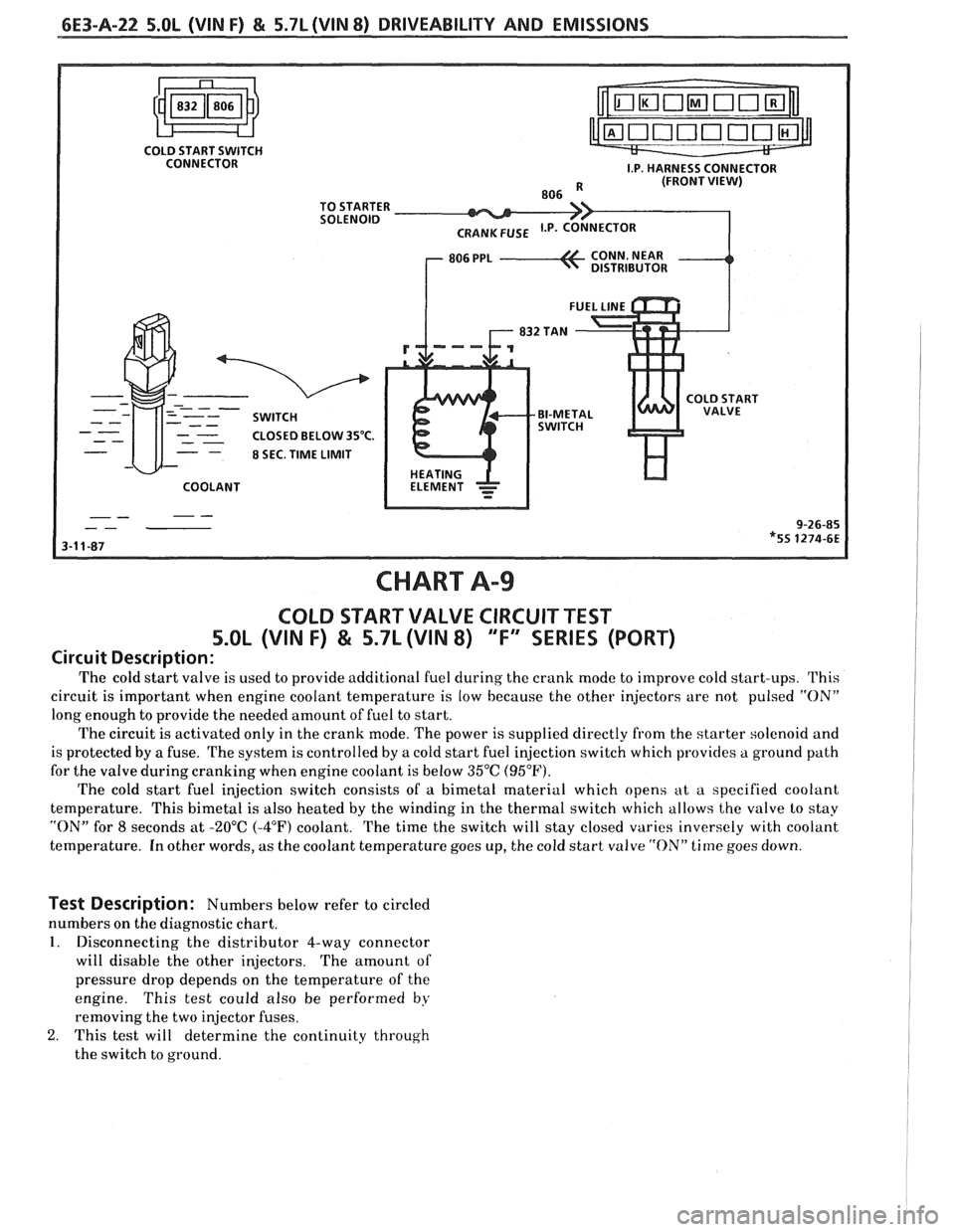
Circuit Description:
The cold start valve is used to provide additional fuel cluring the crank mode to improve cold start-ups. This
circuit is important when engine coolant temperature is low because the other injectors are not pulsed
"ON"
long enough to provide the needed amount of fuel to start.
The circuit is activated only in the crank mode. The power is supplied directly from the starter solenoid and
is protected by a fuse. The system is controlled by a cold start fuel injection switch which provides a ground path
for the valve during cranking when engine coolant is below 35°C (95°F).
The cold start fuel injection switch consists of a bimetal material which opens at a specified coolant
temperature. This bimetal is also heated by the winding in the thertnal switch which allows the valve lo stay
"ON" for 8 seconds at -20°C (-4°F) coolant. The time the switch will stay closed varies inversely with coolant
temperature. In other words, as the coolant temperature goes up, the cold start valve
"ON" time goes down.
Test Description: Numbers below refer to circled
numbers on the diagnostic chart.
1. Disconnecting the distributor 4-way connector
will disable the other injectors. The amount of
pressure drop depends on the temperature of the
engine. This test could also be performed
by
removing the two injector fuses.
2. This test will determine the continuity through
the switch to ground.
Page 867 of 1825
6E3-B-2 5.OL (VIN F) & 5.7L (VIN 8) DRIVEABILITY AND EMISSIONS
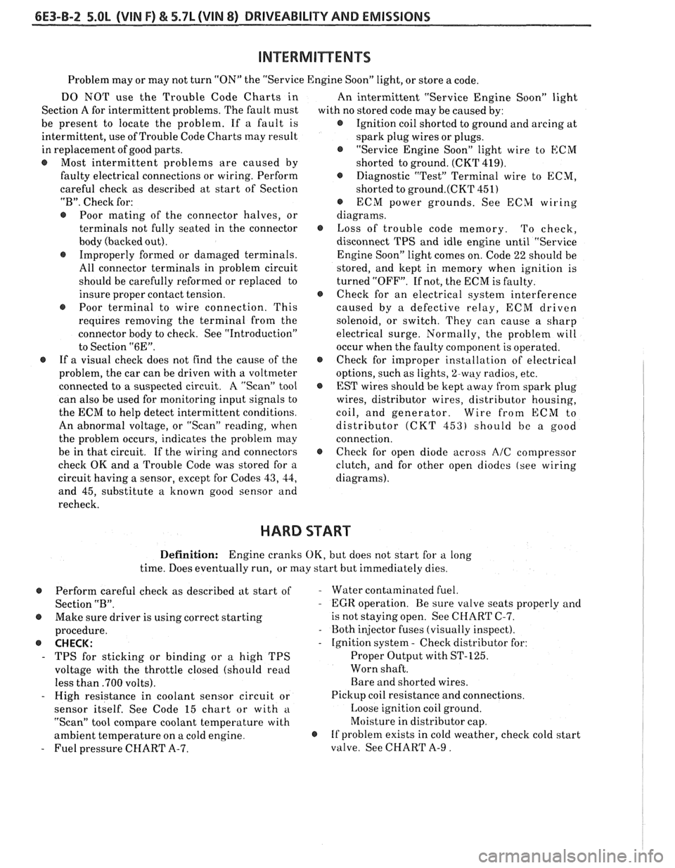
Problem may or may not turn "ON" the "Service Engine Soon" light, or store a code.
DO NOT use the Trouble Code Charts in
An intermittent "Service Engine Soon" light
Section A for intermittent problems. The fault must
with no stored code may be caused by:
be present to locate the problem. If a fault is
@ Ignition coil shorted to ground and arcing at
intermittent, use of Trouble Code Charts
may result
spark plug wires or plugs.
in replacement of good parts.
"Service Engine Soon" light wire to
ECM
@ Most intermittent problems are caused by
shorted to ground. (CKT 419).
faulty electrical connections or wiring. Perform
Diagnostic "Test" Terminal wire to ECM,
careful check as described at start of Section
shorted to
ground.(CKT 451)
"B". Check for:
@ ECM power grounds. See ECSI wiring
@ Poor mating of the connector halves, or diagrams.
terminals not fully seated in the connector
@ Loss of trouble code memory. To check,
body (backed out). disconnect TPS and idle engine until "Service
@ Improperly formed or damaged terminals.
Engine Soon" light comes on. Code 22 should be
All connector terminals in problem circuit
stored, and kept in memory when ignition is
should be carefully reformed or replaced to turned "OFF". If not, the ECM is faulty.
insure proper contact tension.
@ Check for an electrical system interference
@ Poor terminal to wire connection. This caused by a defective relay, ECM driven
requires removing the terminal from the
solenoid, or switch. They can cause a sharp
connector body to check. See "Introduction"
electrical surge. Normally, the problem will
to Section
"6E". occur when the faulty component is operated.
@ If a visual check does not find the cause of the @ Check for improper installation of electrical
problem, the car can be driven with a voltmeter
options, such as lights,
%way radios, etc.
connected to
a suspected circuit. A "Scan" tool
EST wires should be kept away from spark plug
can also be used for monitoring input signals to wires, distributor wires, distributor housing,
the ECM to help detect intermittent conditions. coil, and generator. Wire from
ECM to
An abnormal voltage, or "Scan" reading, when distributor
(CKT 453) should be a good
the problem occurs, indicates the problem
may connection.
be in that circuit. If the wiring and connectors
@ Check for open diode across AIC compressor
check OK and a Trouble Code was stored for a
clutch, and for other open diodes (see wiring
circuit having a sensor, except for Codes
43, 44, diagrams).
and 45, substitute a known good sensor and
recheck.
HARD START
Definition: Engine cranks OK, but does not start for a long
time. Does eventually run, or may start but immediately dies.
Perform careful check as described at start of
Section
"B".
@ Make sure driver is using correct starting
procedure.
@ CHECK:
- TPS for sticking or binding or a high TPS
voltage with the throttle closed (should read
less than
.700 volts).
- High resistance in coolant sensor circuit or
sensor itself. See Code 15 chart or with
a
"Scan" tool compare coolant temperature with
ambient temperature on a cold engine.
- Fuel pressure CHART A-7.
- Water contaminated fuel.
- EGR operation. Be sure valve seats properly and
is not staying open. See CHART C-7.
- Both injector fuses (visually inspect).
- Ignition system - Check distributor for:
Proper Output with ST-125.
Worn shaft.
Bare and shorted wires.
Pickup coil resistance and connections.
Loose ignition coil ground.
Moisture in distributor cap.
@ If problem exists in cold weather, check cold start
valve. See CHART A-9.
Page 1174 of 1825
INTRODUCTION
Power Distribution
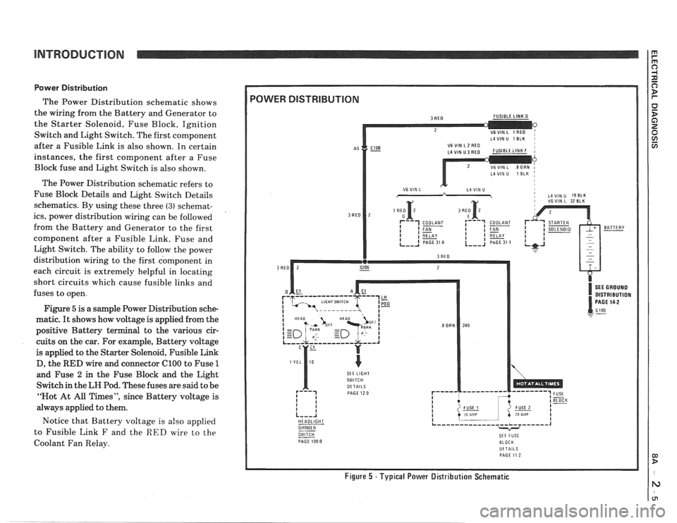
The Power Distribution schematic shows
the wiring from the Battery and Generator to
the Starter Solenoid, Fuse Block, Ignition
Switch and Light Switch. The first component
after a Fusible Link is also shown. In certain
instances, the first component after a Fuse
Block fuse and Light Switch is also shown.
The Power Distribution schematic refers to
Fuse Block Details and Light Switch Details
schematics. By using these three
(3) schemat-
ics, power distribution wiring can be followed
from the Battery and Generator to the first
component after a Fusible Link. Fuse and
Light Switch. The ability to follow the power
distribution wiring to the first component in
each circuit is extremely helpful in locating
short circuits which cause fusible links and
fuses to open.
Figure
5 is a sample Power Distribution sche-
matic.
It shows how voltage is applied from the
positive Battery terminal to the various cir-
cuits on the car. For example, Battery voltage
is applied to the Starter Solenoid, Fusible Link
D, the
RED wire and connector ClOO to Fuse 1
and Fuse 2 in the Fuse Block and the Light
Switch in the
LH Pod. These fuses are said to be
"Not At All Times", since Battery voltage is
always applied to them.
Notice that Battery voltage is
also applied
to Fusible Link
F and the RED wire to the
Coolant Fan Relay.
L4VIN U 1 ELK I
i VSVIN L 32 BLK
DISTRIBUTION
SkE LIGHT
HEADLIGHT
--
PAGE 100 0 BLOCK DETAILS PAGE 11 2
Figure 5 -Typical Power Distribution Schematic
Page 1186 of 1825
TROUBLESHOOTING TESTS m r rn 0
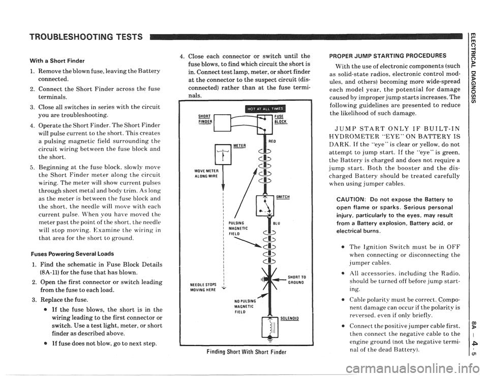
With a Short Finder
1. Remove the blown fuse, leaving the Battery
connected.
2. Connect the Short Finder across the fuse
terminals.
3. Close all switches in series with the circuit
you are troubleshooting.
4. Operate the Short Finder. The Short Finder
will pulse current to the short. This creates
a pulsing magnetic field surrounding the
circuit wiring between the fuse block and
the short.
5. Beginning at the fuse block. slowly move
the Short Finder meter along the circuit
wiring. The meter will show current pulses
through sheet
inetal and body trim. As long
as the meter is between the fuse block and
the short, the needle will move with each
current pulse. When you have
moved the
meter past the point of the short. the needle
will stop
moving. Examine the wiring in
that area for the short to ground.
Fuses Powering Several Loads
1. Find the schematic in Fuse Block Details
(8A-11) for the fuse that has blown.
2. Open the first connector or switch leading
from the fuse to each load.
3. Replace the fuse.
@ If the fuse blows, the short is in the
wiring leading to the first connector or
switch. Use a test light, meter, or short
finder as described above.
@ If fuse does not blow, go to next step.
4. Close each connector or switch until the PROPER JUMP STARTING PROCEDURES
fuse blows, to find which circuit the short is
With the use of electronic components (such
in. Connect test lamp, meter, or short finder
as solid-state radios, electronic control
mod- at the connector to the suspect circuit (dis- ules, and others) becoming more wide-spread
connected) rather than at the fuse termi- each model year, the potential for damage nals. caused by improper jump starts increases. The
SHORT FUSE FINDER - BLOCK -
MOVE METER
NEEDLE STOPS
MOVING HERE
NO PULSING
MAGNETIC
FIELD
Cb
SHORT TO
GROUND
w-
Finding Short With Short Finder
following guidelines are presented to reduce
the likelihood of such damage.
JUMP START ONLY IF BUILT-IN
HYDROMETER "EYE" ON BATTERY IS
DARK. If the "eye" is clear or yellow, do not
attempt to jump start. If the "eye" is green,
the Battery is charged and does not require a
jump start. Both the booster and the dis-
charged Battery should be treated carefully
when using jumper cables.
CAUTION: Do not expose the Battery to
open flame or sparks. Serious personal
injury, particularly
to the eyes, may result
from
a Battery explosion, Battery acid, or
electrical burns.
The Ignition Switch must be in OFF
when connecting or disconnecting the
jumper cables.
All accessories. including the Radio.
should be turned off before jump start-
ing.
Cable polarity must be correct. Compo-
nent damage can occur
if the polarity is
re~~ersed. even if only briefly.
a Connect the positive jumper cable first.
then connect the negative cable to the
engine ground (not the negative termi-
nal of the dead Battery).
Page 1187 of 1825
REPAIR PROCEDURES 0) B
ELECTRICAL REPAIRS
This section provides instruction in the fol-
lowing repairs:
- Circuit Protection
- Typical Electrical Repairs
- Splicing Copper Wire
- Splicing Aluminum \l.ire
- Splicing Txisted Shielded Cable
- Repairing Connectors (Except Weather
Pack
V and
- Repairing breather I'ack * (Environmen-
tal) Connectors
Note: After any electrical repair is made, always
test the circuit by operating the devices in the
circuit. This confirms not only that the repair is
correct, but also that the cause of the complaint
was correctly identified.
CIRCUIT PROTECTION
All electrical circuits are protected against
excessive loads which might occur because of
shorts or overloads in the wiring system. Such
protection is
prolrided by a fuse. circuit
breaker. or fusible link.
Fuses
The most common method of automotive
wiring circuit protection is the fuse. Whenever
there is an excessive amount of current flow-
ing through a circuit the fusible element will
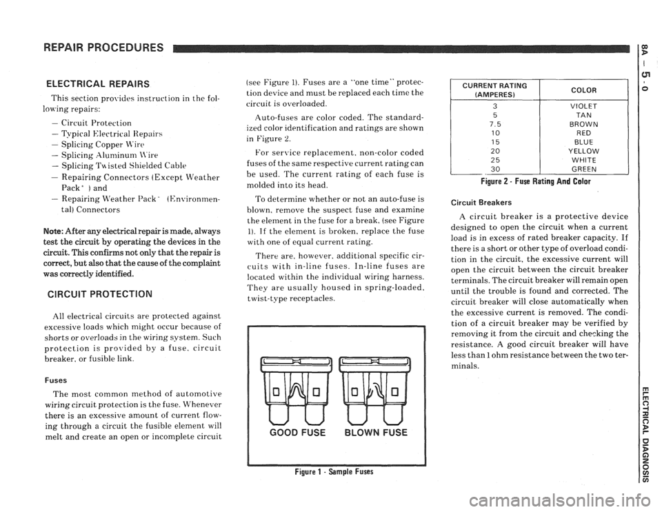
melt and create an open or incomplete circuit (see
Figure
1). Fuses are a "one time" protec-
tion device and must be replaced each time the
circuit is overloaded.
Auto-fuses are color coded. The standard-
ized color identification and ratings are shown
in Figure
2.
For senrice replacement. non-color coded
fuses of the same respective current rating can
be used. The current rating of each fuse is
molded into its head.
To determine whether or not an auto-fuse is
blown, remove the suspect fuse and examine
the element in the fuse for a break, (see Figure
1). If the element is broken, replace the fuse
with one of equal current rating.
There are, however. additional specific cir-
cuits with in-line fuses. In-line fuses are
located within the individual wiring harness.
They are usually housed in spring-loaded,
twist-type receptacles.
GOOD FUSE BLOWN FUSE
Figure 1 - Sample Fuses Figure
2 - Fuse Rating And Galor
CURRENT
RATING
(AMPERES)
3
5
7.5
10
15
20
2
5
30
Circuit Breakers
COLOR
VIOLET
TA N
BROWN RED
BLUE
YELLOW
WHITE
GREEN
A circuit breaker is a protective device
designed to open the circuit when a current
load is in excess of rated breaker capacity. If
there is a short or other type of overload condi-
tion in the circuit, the excessive current will
open the circuit between the circuit breaker
terminals. The circuit breaker will remain open
until the trouble is found and corrected. The
circuit breaker will close automatically when
the excessive current is removed. The condi-
tion of a circuit breaker may be verified by
removing it from the circuit and checking the
resistance.
A good circuit breaker will have
less than
1 ohm resistance between the two ter-
minals.
Page 1188 of 1825
REPAIR PROCEDURES
Fusible Links
In addition to circuit breakers and fuses,
some circuits use fusible links to protect the
wiring. Like fuses, fusible links are "one time
"
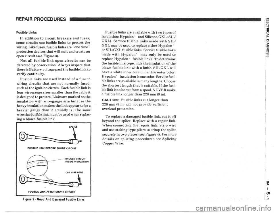
protection devices that will melt and create an
open circuit (see Figure
3).
Not all fusible link open circuits can be
detected by observation. Always inspect that
there is Battery voltage past the fusible link to
verify continuity.
Fusible links are used instead of a fuse in
wiring circuits that are not normally fused,
such as the ignition circuit. Each fusible link is
four wire-gauge sizes smaller than the cable it
is designed to protect. Links are marked on the
insulation with wire-gauge size because the
heavy insulation makes the link appear to be a
heavier gauge than it actually is. The same
wire size fusible link must be used when replac-
ing a blown fusible link.
FUSIBLE LINK BEFORE SHORT CIRCUIT
, BROKEN CIRCUIT INSIDE INSULATION
Fusible links are available with two types of
insulation: Hypalon
bnd SiliconelGXL (SILI
GXL). Service fusible links made with SILI
GXL may be used to replace either Hypalon "
or SILIGXL fusible links. Service fusible links
made with
Hypalonday only be used to
replace Hypalon
"fusible links. To determine
the fusible link type: nick the insulation of the
blown fusible link with a knife.
SILIGXL will
have a white inner core under the outer color.
Hypalon
"nsulation is one color. Service fusi-
ble links are available in many lengths. Choose
the shortest length that is suitable.
If the fusi-
ble link is to be cut from a spool, NEVER make
a fusible link longer than 228 mm
(9 in).
CAUTION: Fusible links cut longer than
228 mm
(9 in) will not provide sufficient
overload protection.
To replace a damaged fusible link, cut it off
beyond the splice. Replace with a repair link.
When connecting the repair link. strip wire
and use staking-type pliers to crimp the splice
securely in two places (see Figure
4). For more
details on splicing procedures see Splicing
Copper Wire.
R SHORT CIRCUIT
Figure 3 - Good And Damaged Fusible Links
-- - - - - -- - - - - -- - - -
Page 1209 of 1825
POWER DISTRIBUTION
CIRCUIT OPERATION
Electrical power for the car is provided by the
Generator when the engine is running. The
schematic diagram shows how each circuit gets
its power. For more details about the Gener-
ator, and connections to the Battery and
Starter, see Starter and Charging System, Sec-
tion
8A-30.
The car's Power Distribution System con-
sists of Fusible Links, Fuses, Circuit Breakers,
the Light Switch and the Ignition Switch. Fusi-
ble Links are short pieces of wire to which they
supply power. They are covered with a special
high-temperature insulation. When conducting
a high current, the Fusible Link will melt and
stop current flow. They are designed to protect
the car's electrical system from electrical
shorts where it is not protected by the Circuit
Breakers and Fuses. See Fuse Block Details
and Light Switch Details for complete wiring to
the first component in each circuit.
The Ignition Switch has six positions, five of
which have detents. The BULB TEST position
is after the RUN position and just before the
START position. BULB TEST does not have a
detent. As shown in the schematic, circuits
which are supplied from the Ignition Switch are
On (Hot) for different switch positions. Indi-
vidual schematics show their fuses supplied
from headings such as "Not In Run. "The head-
ing corresponds to the Ignition Switch position
in which power is On.
Page 1298 of 1825
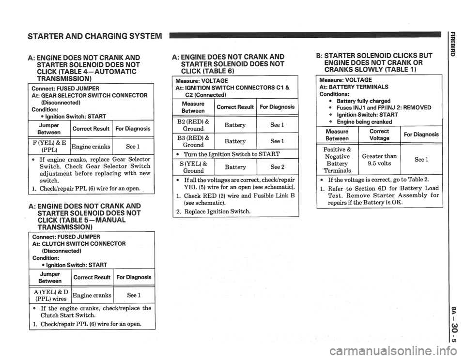
STARTER AND CHARGING SYSTEM
A: ENGINE DOES NOT CRANK AND
STARTER SOLENOID DOES NOT
CLICK (TABLE 4-AUTOMATIC
TRANSMISSION)
Connect: FUSED JUMPER
At: GEAR SELECTOR SWITCH CONNECTOR
(Disconnected)
Condition:
0 Ignition Switch: START
I
Jumper I Corren Resuk I For Diagnosis I Between
I (:::LI& IEngine cranks I See 1 1
If engine cranks, replace Gear Selector
Switch. Check Gear Selector Switch
adjustment before replacing with new
switch.
1. ChecWrepair PPL (6) wire for an open.
A: ENGINE DOES NOT CRANK AND
STARTER SOLENOlD DOES NOT
CLICK (TABLE 5-MANUAL
TRANSMISSION)
Connect: FUSED JUMPER
At: CLUTCH SWITCH CONNECTOR
(Disconnected)
Condition:
I 0 lanition Switch: START I
I :if,",":: 1 Engine cranks I See 1 I
Jumper
Between
If the engine cranks, checklreplace the
Clutch Start Switch.
1. Checklrepair PPL (6) wire for an open.
A: ENGINE DOES NOT CRANK AND B:
STARTER SOLENOID CLICKS BUT
STARTER
SOLENOID DOES NOT ENGINE DOES NOT CRANK OR
CLICK (TABLE 61 CRANKS SLOWLY (TABLE 1)
Correct Result Measure:
VOLTAGE
At: IGNITION SWITCH CONNECTORS
C1 &
C2 (Connected)
For Diagnosis
I Measure ( Correct Result I For Diagnosis 1 Between
I B2 (RED)& I Battery ( See 1 I Ground
I B3 IRED'& I Battery ( See 1 1 Ground
0 Turn the Ignition Switch to START
Measure: VOLTAGE
At: BPirTERV TERMINALS
Conditions: Battery fully charged
0 Fuses lNJ1 and FPIINJ 2: REMOVED
Ignition Switch: START
Engine being cranked
See 2 IYEL' &
Ground
For Diagnosis
See
Measure
Between
Positive &
Negative Battery
Terminals
If
all the voltages are correct, checklrepair
YEL (5) wire for an open (see schematic).
1. Check RED (2) wire and Fusible Link B
(see schematic).
2. Replace Ignition Switch.
Battery
0 If
the voltage is correct, go to Table 2.
1. Refer to Section 6D for Battery Load
Test. Remove Starter Assembly for
repairs if the Battery is
OK.
Correct
Voltage
Greater than
9.5 volts