drain bolt PONTIAC FIERO 1988 Service Repair Manual
[x] Cancel search | Manufacturer: PONTIAC, Model Year: 1988, Model line: FIERO, Model: PONTIAC FIERO 1988Pages: 1825, PDF Size: 99.44 MB
Page 18 of 1825
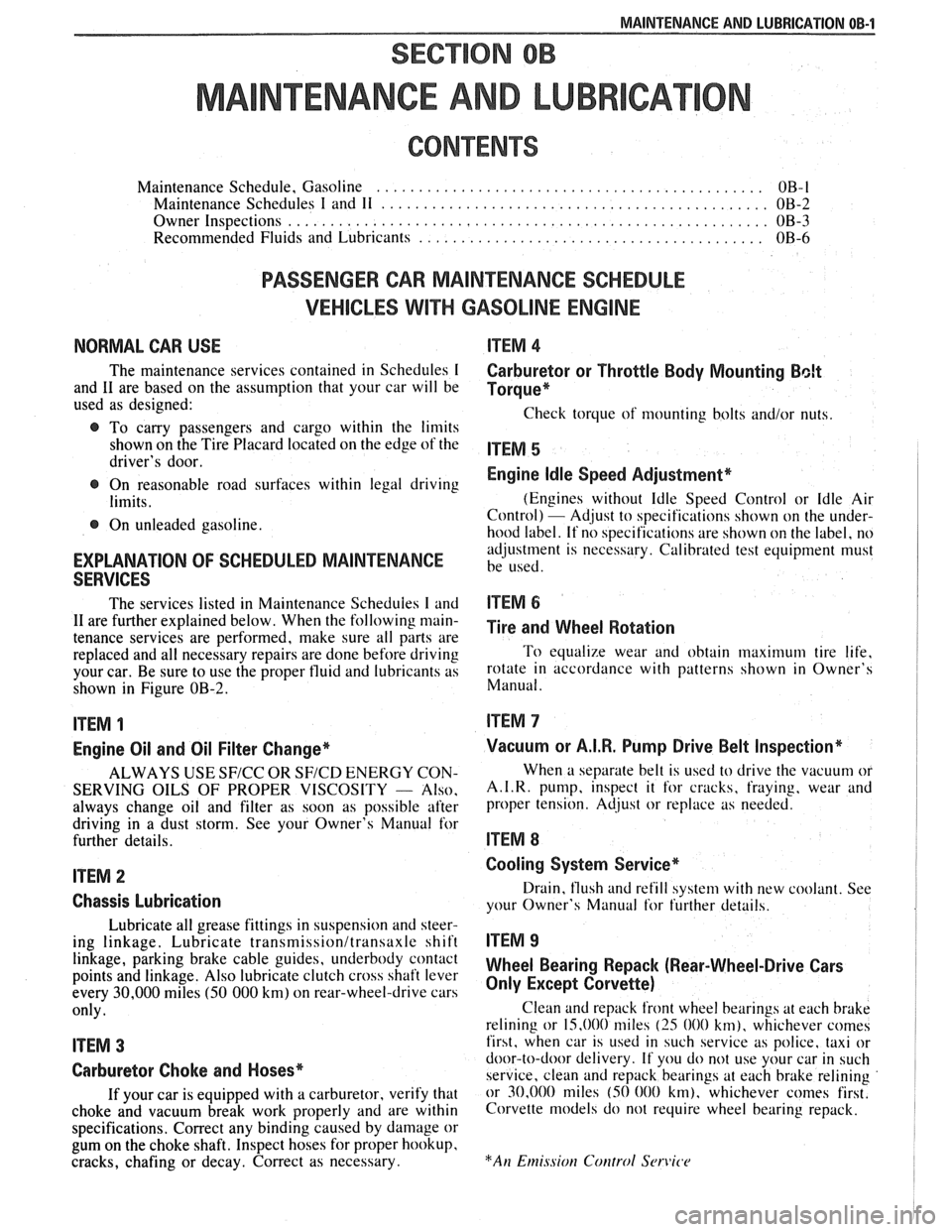
MAINTENANCE AND LUBRICATION OB-1
SECTION OB
NTENANCE AND LUBR
CONTENTS
Maintenance Schedule, Gasoline .............................................. OB-l
Maintenance Schedules I and 11 .............................................. OB-2
Owner Inspections
......................................................... OB-3
Recommended Fluids and Lubricants ......................................... OB-6
PASSENGER CAR MAINTENANCE SCHEDULE
VEHICLES
WITH GASOLINE ENGINE
NORMAL CAR USE ITEM 4
The maintenance services contained in Schedules I Carburetor or Throttle Body Mounting Bolt
and 11 are based on the assumption that your car will be Torque* used as designed:
Check torque of mounting bolts and/or nuts. @ To carry passengers and cargo within the limits
shown on the Tire Placard located on the edge of the ITEM 5 driver's door.
@ On reasonable road surfaces within legal driving Engine Idle Speed Adjustment*
limits. (Engines
without Idle Speed Control or Idle Air
Control) - Adjust to specifications shown on the under- @ On unleaded gasoline.
hood label. If no specifications are shown on the label, no
adjustment is necessary. Calibrated test equipment must
EXPLANATION OF SCHEDULED MAINTENANCE be used. SERVICES
The services listed in Maintenance Scheduies I and ITEM 6
11 are further explained below. When the following main- ~i~~ and wheel aotation tenance services are performed, make sure all parts are
replaced and all necessary repairs are done before driving To equalize wear and obtain maximum tire life,
your car. Be sure to use the proper fluid and lubricants as rotate in accordance with patterns shown in Owner's
shown in Figure OB-2. Manual.
ITEM 1
Engine Oil and Oil Filter Change*
ALWAYS USE SFICC OR SF/CD ENERGY CON-
SERVING OILS OF PROPER VISCOSITY
- Also.
always change oil and filter as soon as possible after
driving in a dust storm. See your Owner's Manual for
further details.
ITEM 2
Chassis Lubrication
Lubricate all grease fittings in suspension and steer-
ing linkage. Lubricate
transmissionltransaxle shift
linkage, parking brake cable guides, underbody contact
points and linkage. Also lubricate clutch cross shaft lever
every
30,000 miles (50 000 km) on rear-wheel-drive cars
only.
ITEM 3
Carburetor Choke and Hoses*
If your car is equipped with a carburetor, verify that
choke and vacuum break work properly and are within
specifications. Correct any binding caused by damage or
gum on the choke shaft. Inspect hoses for proper hookup,
cracks, chafing or decay. Correct as necessary.
Vacuum or A.I.R. Pump Drive Belt Inspection*
When a separate belt is used to drive the vacuum or
A.I.R.
pump, inspect it for cracks, fraying, wear and
proper tension. Adjust or replace as needed.
ITEM 8
Cooling System Service*
Drain, flush and refill system with new coolant. See
your Owner's Manual
for further details.
ITEM 9
Wheel Bearing Repack (Rear-Wheel-Drive Cars
Only Except Corvette)
Clean and repack front wheel bearings at each brake
relining or 15,000 miles
(25 000 km), whichever comes
first, when car is used in such service as police, taxi or
door-to-door delivery. If you do not use your car in such
service, clean and repack bearings at each brake relining
or 30,000 miles
(50 000 km), whichever comes first.
Corvette models do not require wheel bearing repack.
Page 196 of 1825
POWER STEERING 387-3
crocus cloth or fine hone. If the system 4. If the pump checks within specifications, leave
contains some dirt, flush it. If it is the valve open and turn (or have turned) the
exceptionally dirty, both the pump and the steering wheel into both corners. Record the
gear must be completely disassembled, highest pressures and compare with the
cleaned, flushed and reassembled before maximum pump pressure recorded. If this
further usage. pressure cannot be built in either (or one) side of
- the gear, the gear is leaking internally and must
c. If
the pressures recorded are constant, but
be disassembled and repaired. See "Unit Repair"
more than
100 PSI (690 kPa), below the
at the end of this section.
spec.9 rep1ace the flow 8. Shut off engine, remove testing gage, spare hose,
valve and recheck. If the pressures are still
low, replace the rotating group in the pump. reconnect pressure hose, check fluid
level and/or
make needed repairs.
ON-VEHICLE SERVICE
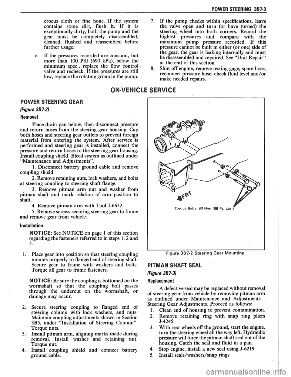
POWER STEERING GEAR
(Figure 387-2)
Removal
Place drain pan below, then disconnect pressure
and return hoses from the steering gear housing. Cap
both hoses and steering gear outlets to prevent foreign
material from entering the system. After service is
performed and steering gear is installed, connect the
pressure and return hoses to the steering gear housing.
Install coupling shield. Bleed system as outlined under
"Maintenance and Adjustments".
1. Disconnect battery ground cable and remove
coupling shield.
2. Remove retaining nuts, lock washers, and bolts
at steering coupling to steering shaft flange.
3. Remove pitman arm nut and washer from
pitman shaft and mark relation of arm position to
shaft.
4. Remove pitman arm with Tool J-6632.
5.
Remove screws securing steering gear to frame
and remove gear from vehicle.
Installation
NOTICE: See NOTICE on page 1 of this section
regarding the fasteners referred to in steps 1,2 and
3.
1. Place gear into position so that steering coupling
mounts properly to flanged end of steering shaft.
Secure gear to frame with washers and bolts.
Torque all gear to frame fasteners.
NOTICE: Be sure the coupling is bottomed on the
wormshaft so that the coupling bolt passes
through the undercut on the wormshaft, or
damage may occur.
2. Secure steering coupling to flanged end of
steering column with lock washers, and nuts.
Maintain coupling adjustments shown in Section
3B5, under "Installation of Steering Column".
Torque nuts.
3. Install pitman arm, aligning marks made during
removal. Install washer and retaining nut.
Torque nut.
4. Install coupling shield and connect battery
ground cable.
Torque Bolts: 90 Nm (66 Ft. ~bs.r
Figure 3B7-2 Steering Gear Mounting
PITMAN SHAFT SEAL
(Figure 387-3)
Replacement
A defective seal may be replaced without removal
of steering gear from vehicle by removing
pitman arm
as outlined under Maintenance and Adjustments
-
Steering Gear Adjustments. Proceed as follows:
1. Clean end of housing to prevent contamination.
2. Remove retaining
ring with snap ring pliers
J-4245.
3. With rear wheels off the ground, start the engine,
turn the steering wheel all the way left. Hydraulic
pressure will force the
pitman shaft seal out of the
housing. Catch the seal and fluid in a pan.
4. Stop engine, install a new seal using 5-6219.
5. Install seals/washers/snap rings.
Page 197 of 1825
3B7-4 POWER STEERING
6. Reinstall pitman arm as described earlier, Add
fluid as required, check and bleed system until
correct fluid level is obtained.
POWER STEERING PUMP
Removal
1. Place drain pan below, then disconnect hoses at
pump or steering gear. When hoses are
disconnected, secure ends in raised position to
prevent drainage of fluid.
2. Install caps at hose fittings to prevent loss of fluid
from pump.
3. Remove drive belt.
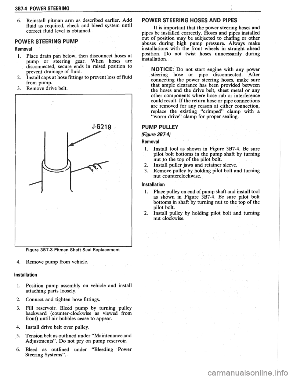
Figure 3B7-3 Pitman Shaft Seal Replacement
4. Remove pump from vehicle.
Installation
1. Position pump assembly on vehicle and install
attaching parts loosely.
2. Gonl7.zct and tighten hose fittings.
3. Fill reservoir. Bleed pump by turning pulley
backward (counter-clockwise as viewed from
front) until air bubbles cease to appear.
4. Install drive belt over pulley.
5. Tension belt as outlined under "Maintenance and
Adjustments". Do not pry on pump reservoir.
6. Bleed as outlined under "Bleeding Power
Steering Systems".
POWER STEERING HOSES AND PIPES
It is important that the power steering hoses and
pipes be installed correctly. Hoses and pipes installed
out of position may be subjected to chafing or other
abuses during high pump pressure. Always make
installations with the front wheels in straight ahead
position. Do not twist hoses unncessarily during
installation.
NOTICE: Do not start engine with any power
steering hose or pipe disconnected. After
connecting the power steering hoses, make sure
that ample clearance has been provided between
the hoses and the drive belt, sheet metal or any
other components where hose rub or interference
could result. If the return hose or pipe connections
are removed for any reason at either connection,
replace the existing "crimped" clamp with a
"worm drive" clamp for proper sealing.
PUMP PULLEY
(Figure 38 7-41
Removal
1. Install tool as shown in Figure 3B7-4. Be sure
pilot bolt bottoms in the pump shaft by turning
nut to the top of the pilot bolt.
2. Install puller jaws and retainer sleeve.
3. Remove pulley by holding pilot bolt and turning
nut counterclockwise.
Installation
1. Place
pulley on end of pump shaft and install tool
as shown in Figure 3B7-4. Be sure pilot bolt
bottoms in shaft by turning nut to the top of the
pilot bolt.
2. Install pulley by holding pilot bolt and turning
nut clockwise.
Page 218 of 1825
FRONT SUSPENSION 3C-7
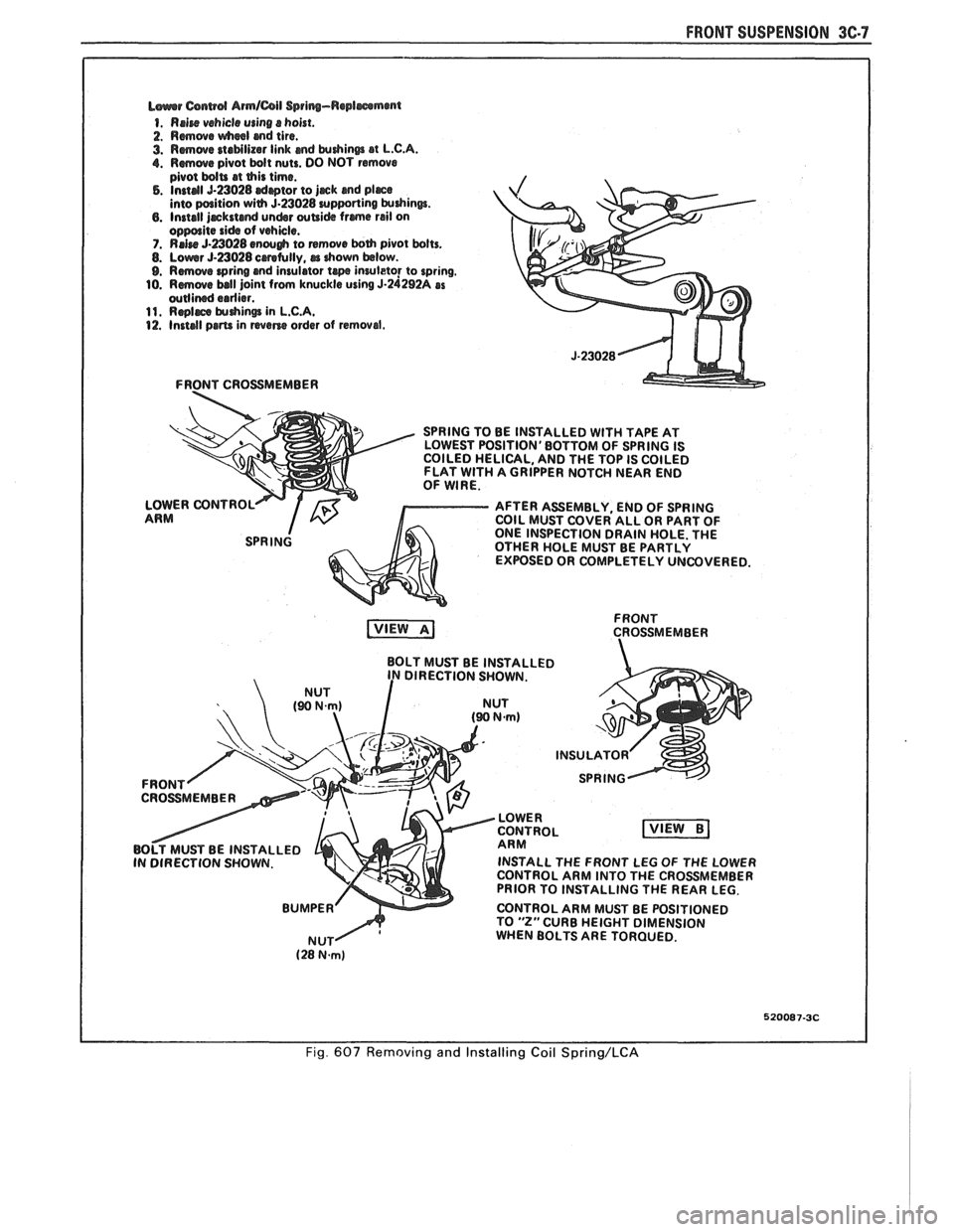
L~urrr Csnwd Armlail Spring-Replmmmt
1. Rrire vehicle using s hoist.
2. Rmwe wheel md tire.
3. Rmwe staMlizar link md krdrinm at L.C.A. 1. Rmwe pivot bdt nuts. DO NOT remove
pivot bdU at this time. 5. Instal 5-23028 drptor to jjrck and pljrce into paition with 5.23028 urpporting krdrinw. 6. Install jrckstcmd undsr wUi& frme rail on oppolite side of vehicle. 7. RrJre 5-a028 enough to remwe both pivot bolts. 8. Lowr 5-23028 crretully, rr drown below. 9. Rmove wring and insulator te inruleto! to spring.
10. Rmwe ball joint from knuckle using 5-24292A as wllined erdier. 11. Rqlrce $uhin@ in L.C.A. 12. Install prm in wane order of removal.
FRONT CROSSMEMBER
SPRING TO BE INSTALLED
WlTH TAPE AT
LOWEST POSITION'BOTTOM OF SPRING IS
COILED HELICAL, AND THE TOP IS COILED
FLAT
WlTH A GRIPPER NOTCH NEAR END
OF WIRE.
LOWER CONTROL
AFTER ASSEMBLY, END OF SPRING
ARM COIL MUST COVER ALL OR PART OF
ONE INSPECTION DRAIN HOLE. THE
OTHER HOLE MUST BE PARTLY
EXPOSED OR COMPLETELY UNCOVERED.
FRONT
CROSSMEMBER
BOLT MUST BE INSTALLED
DIRECTION SHOWN.
INSTALL THE FRONT LEG
OF THE LOWER
CONTROL ARM INTO THE CROSSMEMBER
PRIOR TO INSTALLING THE REAR LEG.
CONTROL ARM MUST BE POSITIONED
TO
"2" CURB HEIGHT DIMENSION
WHEN BOLTS ARE TORQUED.
520087-3C
Fig. 607 Removing and Installing Coil Spring/LCA
Page 254 of 1825
REAR AXLE 481-1
SECTION 4B4
BORG WARNER REAR AXLE
NOTICE: All rear axle attaching fasteners are an
necessary. Do not use a replacement part of lesser
important part in that they could affect the
quality or substitute design. Torque values must
performance of vital parts and systems, and/or
be used as specified during reassembly to assure
could result in major repair expense. They must
proper retention of all parts. (There is to be no
be replaced with one of the same part number or
welding as it may result in extensive damage and
with an equivalent part if replacement becomes
weakening of the metal.)
CONTENTS
General Description ............................... 4B 1- I
......... Standard Rear Axle ................... ..... 4B 1 - 1
General Information ............................. .... 4B 1- 1
Limited-Slip Rear Axle .............................. 4B 1-2
Operation
............................................ 4B 1-3
Diagnosis and Testing .......................... 4B 1-2
Axle Noises
..................... .... .................. 4B 1-2
Gear Noise
................................... .... .. 4B 1-4
Bearing Noise
......................... ...... ... 4B 1-4
Rear Wheel Bearing Noise ..................... 4B 1-4
Knock At Low Speeds
....................... ..... 4B 1-4
Backlash Clunk
................................... 4B 1-4
Diagnosis
................................................ 4B 1-4
Pre-Repair Investigation and Trouble
Diagnosis
....................... .. .................... 4B 1-4
...................................... On-Vehicle Sewice 4B 1-7
Carrier Cover and Gasket .......................... 4B 1-7
.............. Axle Shaft ......................... ....., 4B 1-7
Tooth Contact Pattern Test
................... 4B 1-8
Procedure
.................... .. ...................... 4B 1-8
Effects of Increasing Load on
Teeth Contact Pattern
......................... 4B 1-8
Adjustments Affecting Tooth
................................................ Contact 4B 1-8
Effects of Pinion
Postion on Tooth Pattern
............................................... 4B
1-8
Pinion Oil Seal and Companion
Flange Replacement
................... .. ...... 4B 1-8
Rear Wheel Bolt
........................................ 4B 1 - 10
Rear Axle Assembly
................................... 4B I - 10
Unit Repair
............................................... 4Bl-1 1
Drain Rear Axle Assembly ........................ 4B I - I I
Differential Assembly ............................. 4B 1 - 1 1
Hypoid Pinion & Pinion Bearings .......... 4B 1- I I
Four Pinion Standard Differential
Assembly
....................... ... ........... 4B 1 - 1 3
Inspection
............................................ 4B 1 - I:!
Differential Assembly .......................... 4B 1 - 14
Differential Bearing Preload Spacer
................... ...................... Selection .. 4B I - 11
.................................................. Pinion 4B 1 - 15
Operation of Limited Slip Rear Axle
........................................... (Cone Type) 4B 1 - 17
Checking Limited-Slip Function
............ 4B 1 - 17
......................... Limited Slip Differential 4B 1 - 18
.............. Disassembly Inspection Chart 4B
1- 18
......................... Limited Slip Differential 4B I - 1 X
............................................. Specifications
4B 1- 19
Axle Code Identification Chart
............ 4B 1-19
............................................. Special Tools 4B 1-20
GENERAL DESCRIPTION
STANDARD REAR AXLE All parts necessary to transmit power from the
propeller shaft to the rear wheels are enclosed in a
The rear axle assembly is of the semi-floating type salisbury type axle housing (a carrier casting with tubes
in which the car weight is carried on the axle housing.
pressed and welded into the carrier to form a complete The rear axle assembly is designed for use with an open carrier and tube assembly). A removable steel cover drive line and coil springs. The rear axle has a hypoid bolted to the rear of the carrier permits service of the type ring gear and pinion with the centerline of the rear axle without removing the entire assembly from
pinion gear below the centerline of the ring gear.
the car.
GENERAL INFORMATION
NOTICE: Most rear axle service repairs can be
Two pre-loaded tapered roller bearings support the
made with the rear axle assembly in the car, by
hypoid pinion gear in the carrier. The inner race of the
raising the rear end of the car with the rear axle
rear bearing is a tight press fit on the pinion stem. The
hanging on the shock absorbers.
inner race of the front bearing combines a light press
fit to a close sliding fit on the pinion flange end of the
A universal joint connects the rear end of the pinion stem. The outer race of each bearing is pressed
propeller shaft to a companion flange having a splined against a shoulder recessed in the carrier. Tightening
end which fits over and drives the
hypoid pinion gear. the pinion nut compresses a collapsible spacer which
Page 260 of 1825
REAR AXLE 481-7
ON-VEHICLE SERVICE
CARRIER COVER AND GASKET
Remove or Disconnect
1. Having
a container in place remove drain plug
with tool
J-35117,remove cover bolts and pry
cover loose to drain lubricant.
2. Make sure both
gasket sealing surfaces are clean.
Install or Connect
Use cover gasket (do not assemble with
sealant alone).
NOTICE: Apply locktite part No. 573, GM Part
Nos. 1052080, or 1052279 or equivalent to cover
bolts before installing cover. If sealant is not applied
bolts may loosen causing fluid leak and damage to
rear axle assembly.
1. Torque cover bolts in a crosswise pattern to
insure uniform draw on gasket. Torque
26 N.m
(20 1b.ft.).
2. Fill with lubricant to bottom of filler plug hole.
Refer to specifications for correct lubricant usage
and quantity.
AXLE SHAFT
Remove or Disconnect
1. Wheel
and brake components as necessary.
2. The
four nuts holding the brake anchor plate and
outer bearing retainer.
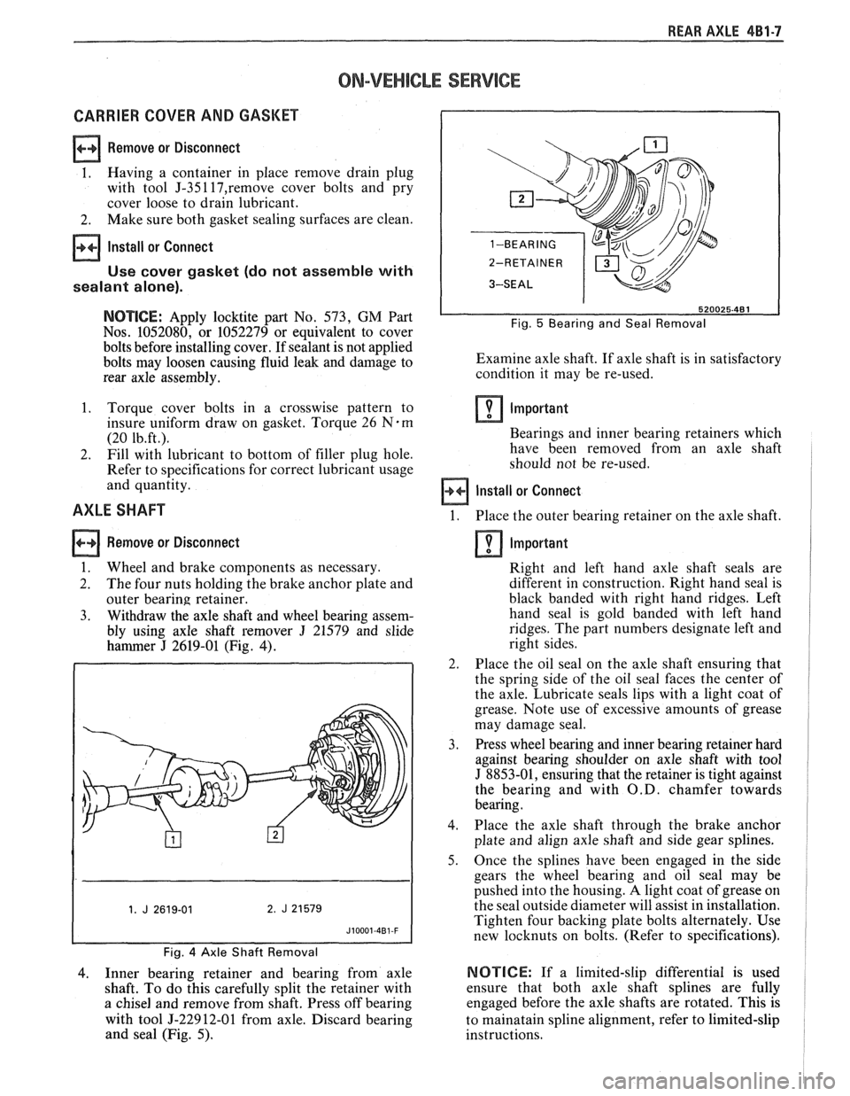
3. Withdraw the axle shaft and wheel bearing assem-
bly using axle shaft remover
J 21579 and slide
hammer
J 2619-01 (Fig. 4).
Fig. 4 Axle Shaft Removal
4. Inner
bearing retainer and bearing from axle
shaft. To do this carefully split the retainer with
a chisel and remove from shaft. Press off bearing
with tool
5-22912-01 from axle. Discard bearing
and seal (Fig. 5).
Fig. 5 Bearing and Seal Removal
Examine axle shaft. If axle shaft is in satisfactory
condition it may be re-used.
Important
Bearings and inner bearing retainers which
have been removed from an axle shaft
should not be re-used.
Install or Connect
1. Place the outer bearing retainer on the axle shaft.
Important
Right and left hand axle shaft seals are
different in construction. Right hand seal is
black banded with right hand ridges. Left
hand seal is gold banded with left hand
ridges. The part numbers designate left and
right sides.
2. Place the oil seal on the axle shaft ensuring that
the spring side of the oil seal faces the center of
the axle. Lubricate seals lips with a light coat of
grease. Note use of excessive amounts of grease
may damage seal.
3. Press wheel bearing and inner bearing retainer hard
against bearing shoulder on axle shaft with tool
J 8853-01, ensuring that the retainer is tight against
the bearing and with
O.D. chamfer towards
bearing.
4. Place the axle shaft through the brake anchor
plate and align axle shaft and side gear splines.
5. Once the splines have been engaged in the side
gears the wheel bearing and oil seal may be
pushed into the housing.
A light coat of grease on
the seal outside diameter will assist in installation.
Tighten four backing plate bolts alternately. Use
new locknuts on bolts. (Refer to specifications).
NOTICE: If a limited-slip differential is used
ensure that both axle shaft splines are fully
engaged before the axle shafts are rotated. This is
to mainatain spline alignment, refer to limited-slip
instructions.
Page 261 of 1825
481.8 REAR AXLE
6. Replace
brake components and wheel.
7. Tighten wheel nuts and lower vehicle.
Tooth Contact Pattern Test
The side of the ring gear tooth which curves
outward, or is convex, is referred to as the "drive" side.
The concave side is the "coast" side. The end of the
tooth nearest center of ring gear is referred to as the
"toe" end. The end of the tooth farthest away from the
center is the "heel" end. Toe end of tooth is smaller
than heel end.
It is very important that tooth contact be tested
before the rear axle carrier assembly is disassembled.
Variations in the carrier or pinion rear bearing may
cause the pinion to be too far away from, or close to,
the ring gear. Thus, the tooth contact must be tested
and corrected, if necessary, or the gears may be noisy.
Procedure
1. Drain
oil out of carrier and carefully clean each
tooth of ring gear.
2. Apply parking brake until a torque of 54 to 70
N-m (40-50 lb. ft.) is required to turn the pinion.
3. Tighten bearing cap bolts to 52 N-m (40 lb. ft.).
4. Use gear marking compound part number
1052351 or equivalent and apply this mixture
sparingly to all ring gear teeth, using a medium
stiff brush. When properly used, the area of
pinion tooth contact will be visible when hand
load is applied.
A test made without loading the gears will not
give a satisfactory pattern. Turn pinion flange
with wrench so that ring gear rotates five full
revolutions, then reverse rotation so that ring
gear rotates five
revolutio~ls in opposite direction.
5. Observe pattern on ring gear teeth and compare
with Fig.
6.
Effects of Increasing Load on Teeth Contact
Pattern
When "load" on ring and pinion gear is
increased, such as when car is accelerated forward
from standstill or from normal drive, the tooth contact
will tend to spread out and, under very heavy load, will
extend from near toe to near heel on the drive side. The
entire contact also tends to shift toward heel under
increasingly heavier loads and will become somewhat
broader with respect to tops and bottoms of teeth. The
patterns obtained by this tooth contact pattern test
approximate a light load and, for this reason, they will
extend only about halfway.
The important thing to note is that the contact
pattern is centrally located up and down on the face of
the ring gear teeth.
Adjustments Affecting Tooth Contact
Two adjustments can be made which will affect
tooth contact pattern, backlash and position of drive
pinion in carrier. The effects of bearing pre-loads are
not readily apparent
on (hand-loaded) tooth contact
pattern tests; however, these adjustments should be within
specifications before proceeding with backlash
and drive pinion adjustments.
Backlash is adjusted by means of the side bearing
adjusting shims, which moves the entire case and ring
gear assembly closer to, or farther from, the drive
pinion (the adjusting shims are also used to set side
bearing pre-load). The position of the drive pinion is
adjusted by increasing or decreasing the shim thickness
between the rear pinion cup and axle housing
. The
shim is used in the rear axle case to compensate for
manufacturing tolerances. Increasing shim thickness
will move the pinion closer to centerline of the ring
gear. Decreasing shim thickness will move pinion
farther away from centerline of the ring gear.
Effects of Pinion Position on Tooth Pattern
When the drive pinion is too far away from
centerline of the ring gear, the pattern will be a high
heel contact on the drive side and high toe contact on
coast side (Fig. 6). Moving the pinion closer to
centerline of the ring gear by increasing shim thickness
will cause the high heel contact on drive side to lower
and move toward the toe; the high toe contact on coast
side will lower and move toward the heel.
When the pinion is too close to the centerline of
the ring gear, the pattern will be a low toe contact on
drive side and a low heel contact on the coast side.
Moving the pinion farther away from the ring gear by
decreasing shim thickness will cause low toe contact on
drive side to raise and move toward the heel; the low
heel contact on coast side will raise and move toward
the toe.
PINION OIL SEAL AND COMPANION FLANGE
REPLACEMENT
Remove or Disconnect
1. Mark the propeller shaft and companion flange
so they can be reassembled in the same position.
Remove four nuts and lock washers from two
saddles retaining
U-joints to companion flange
and remove propeller shaft.
2. Measure and record preload at pinion - this
includes pinion bearing, differential bearings,
effect of grease and oil seal. (Figure
7).
3. Pinion nut with companion flange remover
J-8614-01. (Figure 8).
4. Companion flange with companion flange
remover
5-8614-01. (Figure 8).
5. Seal and discard.
NOTICE: Before installing a new seal examine the
surface of the companion flange on which the seal
runs. Should this surface be damaged or the splines
excessively worn, a new companion flange should
be installed. Also examine the housing bore and
remove any nicks or burrs.
Page 264 of 1825
REAR AXLE 4Bl-I I
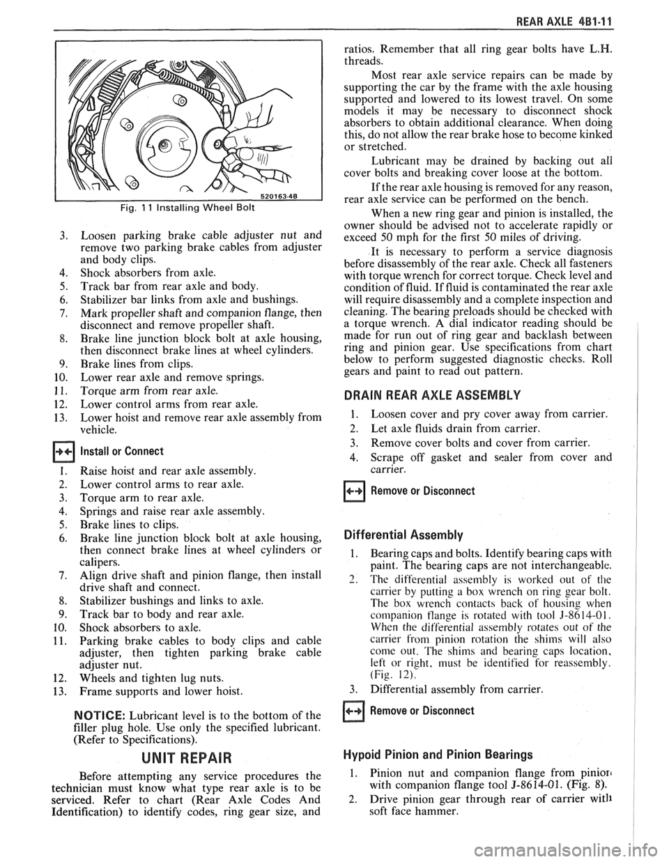
Fig. 11 Installing Wheel Bolt
Loosen parking brake cable adjuster nut and
remove two parking brake cables from adjuster
and body clips.
Shock absorbers from axle.
Track bar from rear axle and body.
Stabilizer bar links from axle and bushings.
Mark propeller shaft and companion flange, then
disconnect and remove propeller shaft.
Brake line junction block bolt at axle housing,
then disconnect brake lines at wheel cylinders.
Brake lines from clips.
Lower rear axle and remove springs.
Torque arm from rear axle.
Lower control arms from rear axle.
Lower hoist and remove rear axle assembly from
vehicle.
Install or Connect
Raise hoist and rear axle assembly.
Lower control arms to rear axle.
Torque arm to rear axle.
Springs and raise rear axle assembly.
Brake lines to clips.
Brake line junction block bolt at axle housing,
then connect brake lines at wheel cylinders or
calipers.
Align drive shaft and pinion flange, then install
drive shaft and connect.
Stabilizer bushings and links to axle.
Track bar to body and rear axle.
Shock absorbers to axle.
Parking brake cables to body clips and cable
adjuster, then tighten parking brake cable
adjuster nut.
Wheels and tighten lug nuts.
Frame supports and lower hoist.
NOTICE: Lubricant level is to the bottom of the
filler plug hole. Use only the specified lubricant.
(Refer to Specifications).
Before attempting any service procedures the
technician must know what type rear axle is to be
serviced. Refer to chart (Rear Axle Codes And
Identification) to identify codes, ring gear size, and ratios.
Remember that all ring gear bolts have
L.H.
threads.
Most rear axle service repairs can be made by
supporting the car by the frame with the axle housing
supported and lowered to its lowest travel. On some
models it may be necessary to disconnect shock
absorbers to obtain additional clearance. When doing
this, do not allow the rear brake hose to become
kinked
or stretched.
Lubricant may be drained by backing out all
cover bolts and breaking cover loose at the bottom.
If the rear axle housing is removed for any reason,
rear axle service can be performed on the bench.
When a new ring gear and pinion is installed, the
owner should be advised not to accelerate rapidly or
exceed 50 mph for the first 50 miles of driving.
It is necessary to perform a service diagnosis
before disassembly of the rear axle. Check all fasteners
with torque wrench for correct torque. Check level and
condition of fluid.
If fluid is contaminated the rear axle
will require disassembly and a complete inspection and
cleaning. The bearing preloads should be checked with
a torque wrench. A dial indicator reading should be
made for run out of ring gear and backlash between
ring and pinion gear. Use specifications from chart
below to perform suggested diagnostic checks. Roll
gears and paint to read out pattern.
DRAIN REAR AXLE ASSEMBLY
1. Loosen cover and pry cover away from carrier.
2. Let axle fluids drain from carrier.
3. Remove cover bolts and cover from carrier.
4. Scrape off gasket and sealer from cover and
carrier.
Remove or Disconnect
Differential Assembly
1. Bearing caps and bolts. Identify bearing caps with
paint. The bearing caps are not interchangeable.
2. The differential assembly is worked out of the
carrier by putting a box wrench on ring gear bolt.
The box wrench contacts back of housing when
companion
tlange is rotated with tool 3-8614-01.
When the differential assembly rotates out of the
carrier from pinion rotation the shims will also
come out. The shims and bearing caps location,
left or right, must be identified for reassembly.
(Fig. 12).
3. Differential assembly from carrier.
Remove or Disconnect
Hypoid Pinion and Pinion Bearings
1. Pinion nut and companion flange from pinion
with companion flange tool 5-8614-01. (Fig. 8).
2. Drive pinion gear through rear of carrier with
soft face hammer.
Page 281 of 1825
4B-8 REAR AXLE
GENERAL lNFORMATlON
A universal joint connects the rear end of the
propeller shaft to a pinion flange, having a splined end
which fits over and drives the
hypoid pinion gear. The
housing is attached to the underbody through a center
bearing support. Inside the housing, an extension shaft
is splined to the drive pinion at the rear end, and to the
companion flange at the other end. Two pre-loaded
tapered roller bearings support the
hypoid pinion gear
in the carrier. The inner race of the rear bearing is a
light press fit on the pinion stem. The inner race of the
front bearing combines a light press fit to a close sliding
fit on the pinion flange end of the pinion stem. The
outer race of each bearing is pressed against a shoulder
recessed in the carrier. Tightening the pinion nut
compresses a collapsible spacer which bears against the
inner race of the front bearing and a shoulder on the
pinion stem. This spacer is used to enable accurate
bearing pre-load adjustment and
maintain a pre-load
on both front and rear pinion bearings. Adjustment of the
fore and aft position of the pinion is obtained by
placing
shims between the head of the drive pinion and
the rear pinion bearing.
The rear axle case is of
one-piece construction and is supported in the carrier
by two tapered roller side bearings. These are
pre-loaded by inserting
shims between the bearings and
the carrier. The rear axle case assembly is positioned
for proper ring gear to pinion backlash by varying the
shin1 thickness from side to side. The ring gear is bolted
to the case. Two side gears have splined bores for
driving the axle shafts. They are positioned to turn in
counterbored cavities in the case. The two rear axle
pinions have
smooth bores and are held in position by
a solid pinion cross shaft, mounted and locked in the
rear axle case. All four gears are in
mesh with each
other and because the pinion gears turn freely
on their
shaft, they act as idler gears when the rear wheels are
turning at different speeds. The pinions and side gears
are backed by steel thrust washers.
LIMITED-SLIP REAR AXLE
The operation of the Limited-Slip differential is
the same as the standard differential, except that there
is additional friction provided by the clutches or cones.
Under ordinary driving and cornering conditions, the
clutches or cones slip, allowing the outside wheel to
turn faster than the inner. Under poor traction
conditions, such as ice, snow, or loose gravel under one
driving wheel, the increased friction provided by the clutches
or cones increases the driving torque available
to the wheel with the better traction. The clutches or
cones are spring loaded to provide the increased
driving torque under extremely low traction
conditions.
Most rear axle service repairs can be made with
the rear axle assembly in the car, by raising the rear end
of the car with the rear axle hanging
on the shock
absorbers.
ON-VEHICLE SERVICE
CARRIER COVER AND GASKET
Remove or Disconnect
1. Having a container in place, remove cover bolts
and pry cover loose to drain lubricant.
2. Make sure both gasket sealing surfaces are clean.
Install or Connect
Use sealant
1052366 or cover gasket
only.
1. Torque cover bolts in a crosswise pattern to
insure uniform draw on gasket. Torque
27 N.m
(20 Ib.fr.).
2. Fill with lubricant to a level within 4.5mm (3116")
or filler plug hole. Refer to specifications for correct
lubricant usage and quantity.
Axle Shaft
a Remove or Disconnect
1. Raise car and remove wheel and brake drum.
2. Clean all dirt from area of carrier.
3. Remove bolts and differential carrier cover and
allow lubricant to drain.
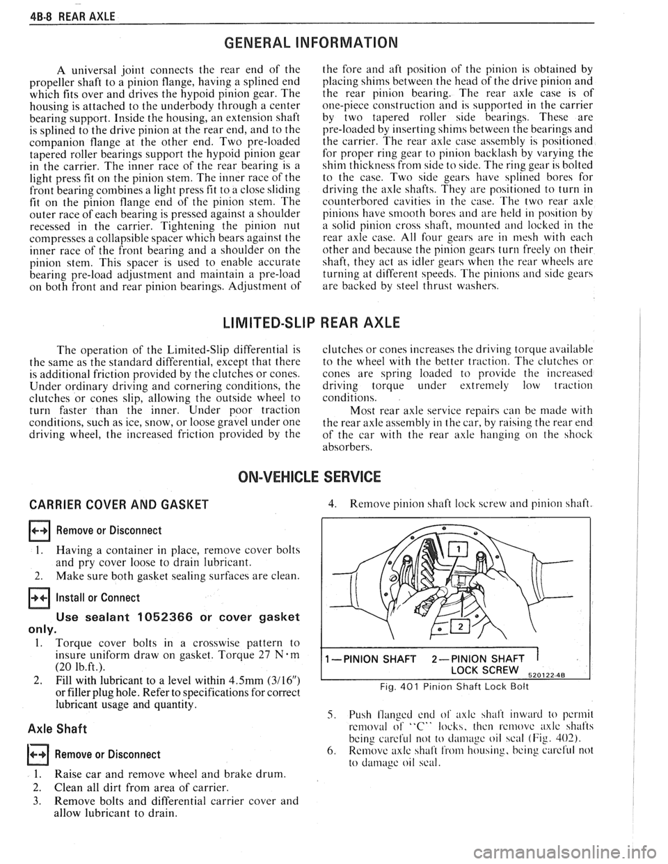
4. Remove pinion shaft lock screw and pinion shaft.
1 -PINION SHAFT 2-PINION SHAFT 1
SCREW 520122 48
Fig. 401 Pinion Shaft Lock Bolt
5. Push flanged end of axlc shalt inward to pcrmil
removal of "C" locks, thcn rcmovc axlc shafts
being
careful not to cl;uii~~gc oil scal (Fig. 402).
6. Remove axlc shaft from housing, bcing curcl'ul not
to
damage oil scal.
Page 284 of 1825
REAR AXLE 48-1 1
Rear Wheel Bolt
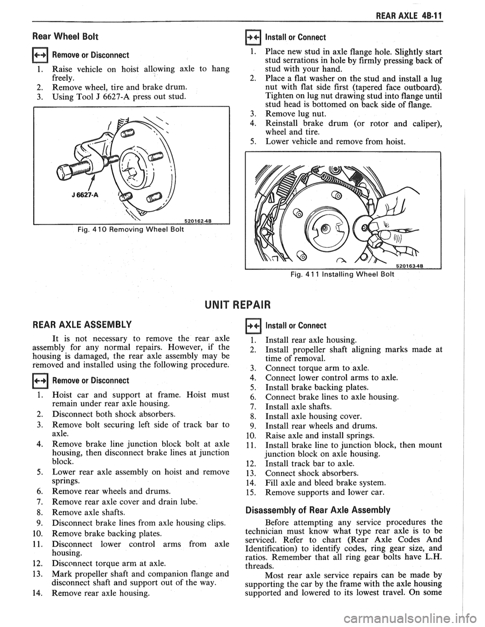
Remove or Disconnect 1.
1. Raise vehicle on hoist allowing axle to hang
freely. 2.
2. Remove
wheel, tire and brake drum.
3. Using Tool J 6627-A press out stud.
Fig. 4 10 Removing Wheel Bolt
REAR AXLE ASSEMBLY
Install or Connect
Fig. 4 11 Installing Wheel Bolt
UNIT REPAIR
Remove or Disconnect
Place new stud in axle flange hole. Slightly start
stud serrations in hole by firmly pressing back of
stud with your hand.
Place a flat washer on the stud and install a lug
nut with flat side first (tapered face outboard).
Tighten on lug nut drawing stud into flange until
stud head is bottomed on back side of flange.
Remove lug nut.
Reinstall brake drum (or rotor and caliper),
wheel and tire.
Lower vehicle and remove from hoist.
It is not necessary to remove the rear axle
assembly for any normal repairs. However, if the
housing is damaged, the rear axle assembly may be
removed and installed using the following procedure.
Hoist car and support at frame. Hoist must
remain under rear axle housing.
Disconnect both shock absorbers.
Remove bolt securing left side of track bar to
axle.
Remove brake line junction block bolt at axle
housing, then disconnect brake lines at junction
block.
Lower rear axle assembly on hoist and remove
springs.
Remove rear wheels and drums.
Remove rear axle cover and drain lube.
Remove axle shafts.
Disconnect brake lines from axle housing clips.
Remove brake backing plates.
Disconnect lower control arms from axle
housing.
Disconnect torque arm at axle.
Mark propeller shaft and companion flange and
disconnect shaft and support out of the way.
Remove rear axle housing.
Install or Connect
Install rear axle housing.
Install propeller shaft aligning marks made at
time of removal.
Connect torque arm to axle.
Connect lower control arms to axle.
Install brake backing plates.
Connect brake lines to axle housing.
Install axle shafts.
Install axle housing cover.
Install rear wheels and drums.
Raise axle and install springs.
Install brake line to junction block, then mount
junction block on axle housing.
Install track bar to axle.
Connect shock absorbers.
Fill axle and bleed brake system.
Remove supports and lower car.
Disassembly of Rear Axle Assembly
Before attempting any service procedures the
technician must know what type rear axle is to be
serviced. Refer to chart (Rear Axle Codes And
Identification) to identify codes, ring gear size, and
ratios. Remember that all ring gear bolts have L.H.
threads.
Most rear axle service repairs can be made by
supporting the car by the frame with the axle housing
supported and lowered to its lowest travel. On some