oil viscosity PONTIAC FIERO 1988 Service Repair Manual
[x] Cancel search | Manufacturer: PONTIAC, Model Year: 1988, Model line: FIERO, Model: PONTIAC FIERO 1988Pages: 1825, PDF Size: 99.44 MB
Page 18 of 1825
MAINTENANCE AND LUBRICATION OB-1
SECTION OB
NTENANCE AND LUBR
CONTENTS
Maintenance Schedule, Gasoline .............................................. OB-l
Maintenance Schedules I and 11 .............................................. OB-2
Owner Inspections
......................................................... OB-3
Recommended Fluids and Lubricants ......................................... OB-6
PASSENGER CAR MAINTENANCE SCHEDULE
VEHICLES
WITH GASOLINE ENGINE
NORMAL CAR USE ITEM 4
The maintenance services contained in Schedules I Carburetor or Throttle Body Mounting Bolt
and 11 are based on the assumption that your car will be Torque* used as designed:
Check torque of mounting bolts and/or nuts. @ To carry passengers and cargo within the limits
shown on the Tire Placard located on the edge of the ITEM 5 driver's door.
@ On reasonable road surfaces within legal driving Engine Idle Speed Adjustment*
limits. (Engines
without Idle Speed Control or Idle Air
Control) - Adjust to specifications shown on the under- @ On unleaded gasoline.
hood label. If no specifications are shown on the label, no
adjustment is necessary. Calibrated test equipment must
EXPLANATION OF SCHEDULED MAINTENANCE be used. SERVICES
The services listed in Maintenance Scheduies I and ITEM 6
11 are further explained below. When the following main- ~i~~ and wheel aotation tenance services are performed, make sure all parts are
replaced and all necessary repairs are done before driving To equalize wear and obtain maximum tire life,
your car. Be sure to use the proper fluid and lubricants as rotate in accordance with patterns shown in Owner's
shown in Figure OB-2. Manual.
ITEM 1
Engine Oil and Oil Filter Change*
ALWAYS USE SFICC OR SF/CD ENERGY CON-
SERVING OILS OF PROPER VISCOSITY
- Also.
always change oil and filter as soon as possible after
driving in a dust storm. See your Owner's Manual for
further details.
ITEM 2
Chassis Lubrication
Lubricate all grease fittings in suspension and steer-
ing linkage. Lubricate
transmissionltransaxle shift
linkage, parking brake cable guides, underbody contact
points and linkage. Also lubricate clutch cross shaft lever
every
30,000 miles (50 000 km) on rear-wheel-drive cars
only.
ITEM 3
Carburetor Choke and Hoses*
If your car is equipped with a carburetor, verify that
choke and vacuum break work properly and are within
specifications. Correct any binding caused by damage or
gum on the choke shaft. Inspect hoses for proper hookup,
cracks, chafing or decay. Correct as necessary.
Vacuum or A.I.R. Pump Drive Belt Inspection*
When a separate belt is used to drive the vacuum or
A.I.R.
pump, inspect it for cracks, fraying, wear and
proper tension. Adjust or replace as needed.
ITEM 8
Cooling System Service*
Drain, flush and refill system with new coolant. See
your Owner's Manual
for further details.
ITEM 9
Wheel Bearing Repack (Rear-Wheel-Drive Cars
Only Except Corvette)
Clean and repack front wheel bearings at each brake
relining or 15,000 miles
(25 000 km), whichever comes
first, when car is used in such service as police, taxi or
door-to-door delivery. If you do not use your car in such
service, clean and repack bearings at each brake relining
or 30,000 miles
(50 000 km), whichever comes first.
Corvette models do not require wheel bearing repack.
Page 55 of 1825
18-12 AIR CONDITIONING
ELEGTRICAWACUUM SYSTEM
DIAGNOSIS
When diagnosing problems in the electrical sys-
tems of the air conditioning system, consult section
8A.
LEAK TESTING THE REFRIGERANT
SYSTEM
Whenever a refrigerant leak is suspected in the
system or a service operation performed which results
in disturbing lines or connections, it is advisable to
test for leaks.
Liquid Leak Detectors
There are a number of locations (fittings,
valves, etc.) on the air conditioning system where a
liquid leak detector solution may be used to pinpoint
refrigerant leaks.
By applying test solution to the area in question
with the swab that is attached to the bottle cap, bub-
bles will form within seconds if there is a leak.
For restricted access areas, such as sections of
the evaporator and condenser, an electronic leak
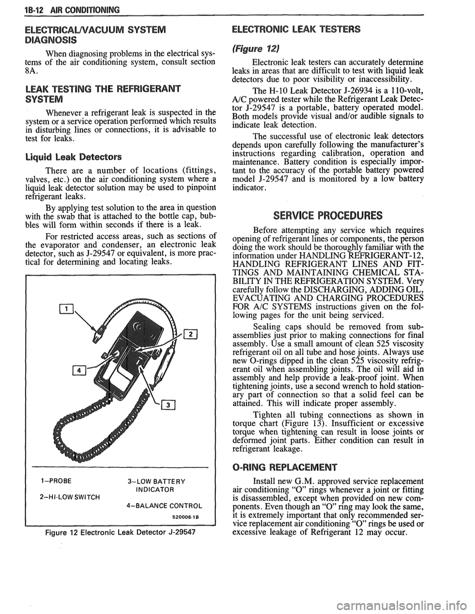
detector, such as
5-29547 or equivalent, is more prac-
tical for determining and locating leaks.
3-LOW BATTERY
INDICATOR
2-HI-LOW SWITCH
4-BALANCE CONTROL
Figure 12 Electronic Leak Detector J-29547
ELECTRONIC LEAK TESTERS
(Figure 12)
Electronic leak testers can accurately determine
leaks in areas that are difficult to test with liquid leak
detectors due to poor visibility or inaccessibility.
The H-10 Leak Detector 5-26934 is a 110-volt,
A/C powered tester while the Refrigerant Leak Detec-
tor J-29547 is a portable, battery operated model.
Both models provide visual
and/or audible signals to
indicate leak detection.
The successful use of electronic leak detectors
depends upon carefully following the manufacturer's
instructions regarding calibration, operation and
maintenance. Battery condition is especially impor-
tant to the accuracy of the portable battery powered
model
5-29547 and is monitored by a low battery
indicator.
SERVICE PROCEDURES
Before attempting any service which requires
opening of refrigerant lines or components, the person
doing the work should be thoroughly familiar with the
information under HANDLING REFRIGERANT- 12,
HANDLING REFRIGERANT LINES AND FIT-
TINGS AND MAINTAINING CHEMICAL STA-
BILITY IN THE REFRIGERATION SYSTEM. Very
carefully follow the DISCHARGING, ADDING OIL,
EVACUATING AND CHARGING PROCEDURES
FOR
A/C SYSTEMS instructions given on the fol-
lowing pages for the unit being serviced.
Sealing caps should be removed from sub-
assemblies just prior to making connections for final
assembly. Use a small amount of clean 525 viscosity
refrigerant oil on all tube and hose joints. Always use
new O-rings dipped in the clean 525 viscosity refrig-
erant oil when assembling joints. The oil will aid in
assembly and help provide a leak-proof joint. When
tightening joints, use a second wrench to hold station-
ary part of connection so that
a solid feel can be
attained. This will indicate proper assembly.
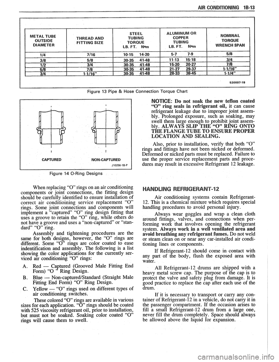
Tighten all tubing connections as shown in
torque chart (Figure
13). Insufficient or excessive
torque when tightening can result in loose joints or
deformed joint parts. Either condition can result in
refrigerant leakage.
O-RING REPWCEMENT
Install new G. M. approved service replacement
air conditioning
"0" rings whenever a joint or fitting
is disassembled, except when provided on new com-
ponents. Even though an
"0" ring may look the same,
it is extremely important that only recommended ser-
vice replacement air conditioning
"0" rings be used or
excessive leakage of Refrigerant 12 may occur.
Page 56 of 1825
-
AIR CONDlTlQNlNG 1B-'13
METAL TUBE
THREAD AND
FITTING SIZE
Figure 13 Pipe 8( Hose
CAPTURED NOM-CAPTURED
Figure 14 0-Ring Designs
When replacing "0" rings on an air conditioning
components or joint connections, the fitting design
should be carefully identified to ensure installation of
correct air conditioining service replacement
"0"
rings. Some joint connections and components will
implement a "captured"
"0" ring design fitting that
uses a groove to retain the
"0" ring, while others do
not have a groove and uses a "non-captured" or "stan-
dard"
"0" ring.
Assembly and tightening procedures are the
same for both designs, however, the
"0" rings are
different. Some
"0" rings are color coated to ease
indentification and assembly. The following is a list
showing the color applications for the currently ser-
viced air conditioning
"0" rings:
A. Red
- Captured
(Grooved Male Fitting End
Fom) "0 " Ring Design.
B . Blue - Non-captured/Standard (Straight Male
Fitting End
Form) "09' Ring Design.
61. Yellow - "0" rings used on different types of
air conditioning switches.
These colored "O" rings are available in various
sizes for each application.
"0" rings should be coated
with
525 viscosity refrigerant oil, prior to installation,
but must not be soaked. Soaking color coated
"0"
rings will cause them to swell.
Connection Torque Chart
NOTICE: Do not soak the new teflon coated
"0" ring seals in refrigerant oil, it can cause
refrigerant leakage due to improper joint assem-
bly. Prolonged exposure, such as soaking, may
swell them large enough to prohibit joint assem-
bly.
ALWAYS SLIP THE 6"O" RING ONTO
THE FLANGE TUBE TO ENSURE PROPER
LOCATION AND SEALING.
Also, prior to installation, verify that both "09'
rings and fittings have not been nicked or deformed.
Deformed or nicked
parts must be replaced. Failure to
use the proper service replacement parts and proce- dures may result in excessive Refrigerant
12 leakage.
HANDLING REFRIGERANT12
Air conditioning systems contain Refrigerant-
12. This is a chemical mixture which requires special
handling procedures to avoid personal injury.
Always wear goggles and wrap a clean cloth
around fittings, valves, and connections when per-
forming work that involves opening the refrigerant
system.
Always work in a well ventilated area and
avoid breathing
any refrigerant fumes. Do not weld
or steam clean on or near any car-installed air condi-
tioning lines or components.
If Refrigerant-12 should come in contact with
any part of the body, flush the exposed area with
water.
All
Refrigerant-12 drums are shipped with a
heavy metal screw cap. The purpose of the cap is to
protect the valve and safety plug from damage. It is
good practice to replace the cap after each use of the
drum.
If it is necessary to transport or carny any con-
tainer of Refrigerant-12 in a vehicle, do not
carry it in
the passenger compartment. If the occasion arises to
fill a
sfnall Refrigerant-12 drum from a large one,
never fill the drum completely. Space should always
be allowed above the liquid for expansion.
Page 57 of 1825
18-14 AIR CONDITIONING
HANDLING OF REFRIGERANT LINES AND
FI-INGS
Tighten all tubing connections as shown in
torque chart (Figure 13). INSUFFICIENT OR
EXCESSIVE TORQUE WHEN TIGHTENING CAN
RESULT IN LOOSE JOINTS OR DEFORMED
JOINT PARTS. Either condition can result in refrig-
erant leakage.
All metal tubing lines should be free of dents or
kinks to prevent loss of system capacity due to line
restriction.
@ The flexible hose lines should never be bent to a
radius of less than four (4) times the diameter of
the hose.
@ The flexible hose lines should never be allowed
to come within a distance of
63.5mm (2-112") of
the exhaust manifold.
@ Flexible hose lines should be inspected regularly
for leaks or brittleness and replaced with new
lines if deterioration or leaking is found.
@ When disconnecting any fitting in the refrigera-
tion system, the system must first be discharged
of all Refrigerant- 12. Proceed very cautiously
regardless of gauge readings. Open very slowly,
keeping face and hands away so that no injury
can occur if there happens to be liquid
Refriger-
ant-12 in the line. If pressure is noticed when
fitting is loosened, allow it to bleed off as
described under DISCHARGING, ADDING
OIL, EVACUATING AND CHARGING PRO-
CEDURES FOR
A/C SYSTEMS.
@ In the event any refrigerant line is opened to the
atmosphere, it should be immediately capped or
taped to prevent entrance of moisture and dirt,
which can cause internal compressor wear or
plugged lines, in the condenser and evaporator
core and expansion (orifice) tubes or compressor
inlet screens.
@ The use of the proper wrenches when making
connections on O-ring fittings is important. The
opposing fitting should always be backed up
with a wrench to prevent distortion of connecting
lines or components. When connecting the flexi-
ble hose connections, it is important that the
swaged fitting and the flare nut, as well as the
coupling to which it is attached, be held at the
same time using three
(3) different wrenches to
prevent turning the fitting and damaging the
ground seat.
@ O-rings and seats must be in perfect condition. A
burr or piece of dirt may cause a refrigerant leak.
When replacing the O-ring, first dip it in clean
525 viscosity refrigeration oil.
MAINTAINING CHEMICAL STABILITY IN
THE
REFRIGERATION SYSTEM
The efficient operation and life of the air condi-
tioning system is dependent upon the chemical stabil-
ity of the refrigeration system. When foreign materials, such as
dirt, air, or moisture, contaminate
the refrigeration system, they will change the stability
of the Refrigerant-12 and 525 viscosity compressor
oil. They will also affect pressure-temperature rela-
tionship, reduce efficient operation and possibly cause
interior corrosion and abnormal wear of moving parts.
The following general practices should be
observed to insure chemical stability in the system:
1. Before disconnecting a refrigerant connection,
wipe away any dirt or oil at and near the connec-
tion to reduce the possibility of dirt entering the
system. Both sides of the connection should be
capped, plugged or taped as soon as possible to
prevent the entry of dirt, foreign material and
moisture.
2. Keep tools clean and dry. This includes the
manifold gauge set and replacement parts.
3. When adding 525 viscosity refrigerant oil (see
ADDING OIL in the DISCHARGING,
ADDING OIL, EVACUATING AND
CHARGING PROCEDURES FOR
AIC SYS-
TEMS, the transfer device and container should
be clean and dry to assure that refrigeration oil
remains as moisture-free as possible.
4. When it is necessary to "open" an
AIC system,
have everything needed ready and handy so that
as little time as possible will be required to per-
form the operation. Do not leave the
AIC system
open any longer than is necessary.
5. Any time the
A/C system has been "opened," it
should be properly evacuated before recharging
with Refrigerant- 12 according to the DIS-
CHARGING, ADDING OIL, EVACUATING
& CHARGING PROCEDURES FOR AIC
SYSTEMS.
All service parts are dehydrated and sealed
prior to shipping. They should remain sealed until just
prior to making connections. All parts should be at
room temperature before uncapping. (This prevents
condensation of moisture from the air entering the
system.) If, for any reason, caps are removed but the
connections are not made, parts should be resealed as
soon as possible.
DISCHARGING, ADDING OIL,
EVACUATING AND CHARGING
PROCEDURES FOR NC SYSTEMS
The refrigerant system may be discharged,
evacuated and charged using air conditioning service
charging station J-23500-01 or equivalent, or the
manifold and gauge set
5-23575-01 and 420ml (14
oz.) disposable cans of Refrigerant-12 (Figure 16).
Charging lines from the charging station or
manifold and gauge set require the use of gauge
adapters to connect to the system service fitting.
A
straight gauge adapter 5-5420 and a 90" angle gauge
adapter
5-9459 are available (see A/C Special Tools).
Always wear goggles and wrap a clean cloth
around fittings and connections when doing work that
Page 58 of 1825
AIR GONDlTlONlNG 1B-15
involves opening the refrigeration system. Always
work in a well ventilated area and avoid breathing any
refrigerant fumes. If liquid refrigerant comes into con-
tact with the eyes, injury may result.
@ Before removing and replacing any of the air
conditioning refrigeration lines or components,
the system must be completely discharged of
Refrigerant- 12.
@ Always use service valve and pressure gauge
sets during evacuation and charging procedures.
@ Always discharge system at low-side service fit-
ting and perform the entire evacuate and charg-
ing procedure through the low-side service
fitting.
@ Do not connect high-pressure line or any line to
the high-side
service fitting during discharging
and charging procedures.
CAUTION: Never remove a gauge line
from its adapter when line is connected
to
AIC system. Always remove the line
adapter from the service
fining to dis-
connect a line. Do not remove charging
hose at gauge set while
anached to ser-
vice low-side
fining. This will result in
complete discharge of system due to
the depressed Schrader valve in
service
low-side fining and may cause personal
injury due to escaping Refrigerant-12.
Discharging the NG System
In replacing any of the air conditioning refriger-
ation components, the system must be completely dis-
charged of Refrigerant- 12.
ALWAYS DISCHARGE SYSTEM AT
LOW-SIDE SERVICE FITTING.
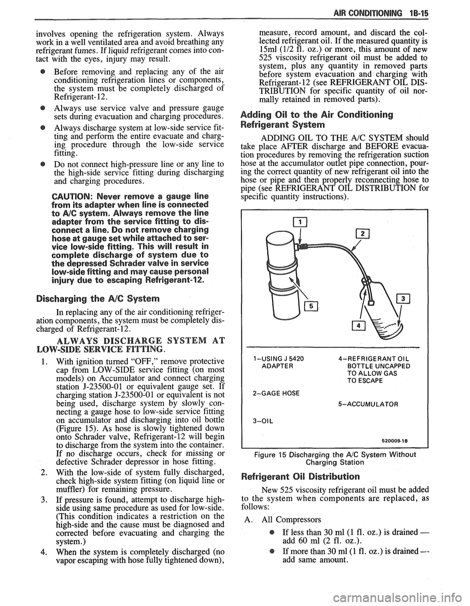
1. With ignition turned "OFF," remove protective
cap from LOW-SIDE service fitting (on most
models) on Accumulator and connect charging
station
J-23500-01 or equivalent gauge set. If
charging station J-23500-01 or equivalent is not
being used, discharge system by slowly con-
necting a gauge hose to low-side
sewice fitting
on accumulator and discharging into oil bottle
(Figure 15). As hose is slowly tightened down
onto Schrader valve, Refrigerant-12 will begin
to discharge from the system into the container.
If no discharge occurs, check for missing or
defective Schrader depressor in hose fitting.
2. With the low-side of system fully discharged,
check high-side system fitting (on liquid line or
muffler) for remaining pressure.
3. If pressure is found, attempt to discharge high-
side using same procedure as used for low-side.
(This condition indicates a restriction on the
high-side and the cause must be diagnosed and
corrected before evacuating and charging the
system.)
4. When the system is completely discharged (no
vapor escaping with hose fully tightened down), measure, record
amount, and discard the col-
lected refrigerant oil. If the measured quantity is
15ml (112 fl. 02.) or more, this amount of new
525 viscosity refrigerant oil must be added to system, plus any quantity in removed parts
before system evacuation and charging with
Refrigerant-12 (see REFRIGERANT OIL DIS-
TRIBUTION for specific quantity of oil nor-
mally retained in removed parts).
Adding Oil to the Air Conditioning
Refrigerant System
ADDING OIL TO THE A/C SYSTEM should
take place AFTER discharge and BEFORE evacua-
tion procedures by removing the refrigeration suction
hose at the accumulator outlet pipe connection, pour-
ing the correct quantity of new refrigerant oil into the
hose or pipe and then properly reconnecting hose to
pipe (see REFRIGERANT OIL DISTRIBUTION for
specific quantity instructions).
1-USING J 5420 4-REFRIGERANT OIL BOTTLE UNCAPPED
TO ALLOW GAS
TO ESCAPE
2-GAGE HOSE 5-ACCUMULATOR
Figure 15 Discharging the A/C System Without
Charging Station
Refrigerant Oil Distribution
New 525 viscosity refrigerant oil must be added
to the system when components are replaced, as
follows:
A. All Compressors
@ If less than 30 ml(1 fl. oz.) is drained -
add 60 ml (2 fl. oz.).
@ If more than 30 ml(1 fl. oz.) is drained --
add same amount.
Page 59 of 1825
"18-16 AIR CONDITIONING
B . Accumulator dehydrator
@ Add 105 ml (3.5 fl. 02.) to new
accumulator
C. Evaporator
@ Add 90 ml (3 fl. oz.) oil
D. Condenser
@ Add 30 ml (1 fl. 02.) oil
Refrigerant oil loss due to a large leak
If the refrigerant charge is aburptly lost due to a
large refrigerant leak, approximately 90
ml (3 fl. oz.)
of refrigerant oil will be
carried out of the system sus-
pended in the refrigerant. Any failure that caused an
abrupt refrigerant discharge will experience this oil
loss. Failures that allow the refrigerant to seep or
bleed off over time do not experience this oil loss.
Upon replacement of a component which
caused a large refrigerant leak, add 90 ml(3
fl. oz.) of
new 525 viscosity refrigerant oil plus the required
amount of oil for the particular component (as out-
lined above).
Add the oil directly to the replaced component if
possible. If the oil cannot easily be added to the
replaced part, add the oil to the accumulator.
Evacuating and Charging the A/C System
If the system has been opened for any repair, or
the Refrigerant-12 charge lost, the system must be
evacuated prior to charging.
Evacuating and charging is a combined proce-
dure, and all gauge lines must be purged with R-12
prior to charging.
There are three evacuate and charge procedures.
1.
J 23500-01 Charging Station Method
2. Disposable Can Method 3. Drum Method
NOTICE: Under no circumstances should alco-
hol be used in the system in an attempt to remove
moisture. Damage to the system components
could occur.
Gauge Calibration
Prior to evacuation, check the low-pressure
gauge for proper calibration and determine if vacuum
system is operating properly.
With the gauge disconnected from the refrigera-
tion system, be sure that the pointer indicates to the
center of
"0". Lightly tap gauge a few times to be sure
pointer is not sticking. If necessary, calibrate as
follows:
1. Remove cover from gauge.
2. Holding gauge pointer adjusting screw firmly
with one hand, carefully force pointer in the
proper direction to position pointer at the
"0"
position. Tap gauge a few times to be sure
pointer is not sticking. Replace gauge cover.
Vacuum System Check
Before connecting vacuum pump to the A/C
system, run pump connected to the low-pressure
gauge to determine the vacuum pump capability. If
the vacuum system is unable to reach
7 1 1.2-736.6mm
(28"-29") or more vacuum, the system should be
checked for leaks. If no leaks are found, the vacuum
pump may require repair.
5-23580-81 OR EQUIVALENT CHARGING
STATION METHOD.
Follow charging instructions provided with the
5-23500-01 Charging Station or equivalent in use with
the following exceptions:
1. Do
not connect the high-pressure line to the air
conditioning system.
2. Keep the high-pressure valve on the charging
station closed at all times.
3.
Perform the entire evacuate and charge proce-
dure through the accumulator low-side pressure service fitting.
4. Following these procedures will prevent acci-
dental high-side vehicle system pressure being
subjected to the charging station in the event an
error is made in valve sequence during compres-
sor operation to pull in the Refrigerant-12
charge.
DISPOSABLE CAN OR REFRIGERANT
DRUM METHOD.
If the Refrigerant-12 drum is used, place it on a
scale and note the total weight before charging. Watch
the scale during charging to determine the amount of
R-12 used.
If disposable
420ml (14 ounce) R-12 cans are
used, close the tapping valve and then attach
can(s)
following instructions included with the tapping valve
or tapping manifold adapter.
1. Connect manifold gauge set 5-23575-01 as fol-
lows. Also see Figure 16.
a. Eow-pressure gauge to accumulator fit-
ting.
b. Gauge set center hosk to Refrigerant-12
source.
c. High-pressure gauge to vacuum pump.
2. To begin evacuation of the
A/C system with
manifold gauge set and vacuum pump as illus-
trated in Figure 16, slowly open
high- and low-
side gauge valves and begin vacuum pump oper-
ation. Pump the system until the low-side gauge
reaches 7 1
1.2-736.6mm (28"-29") vacuum.
Note that in all evacuation procedures, the spec-
ification of 7 1
1.2-736.6mm (28"-29") vacuum is
used. This specification can only be reached at
or near sea level. For each
304.8m (1,000 feet)
above sea level, specification should be lowered
by one inch vacuum. At
1524m (5,000 feet)
elevation, only
584.2-609.6mm (23"-24") of
vacuum is required.
Page 62 of 1825
AIR CONDITIONING 18-19
3. Push the tube into the fitting, bottoming it out.
Tighten
@ Torque nut to 15 Nam (11 lbs. ft.).
4. Dissasemble the joint.
5. Lubricate the
"0" ring with clean 525 viscosity
refrigerant oil.
6. Install the
"0" ring
on the tube. (See figure 17b)
7. Reassemble joint.
Tighten
@ Torque nut to 15 Nem (11 lbs. ft.).
8. Evacuate, charge, and leak test the system.
EXPANSlON "%BE (ORIFICE) SERVlCE
Remove or Disconnect
1. Discharge system.
2. Loosen fitting
at liquid line to evaporator inlet
pipe and remove tube carefully with needle
nosed pliers or Tool
5-26549-C or equivalent.
Install or Connect
1. Install
new orifice tube with shorter screen end
in first.
2. Install
liquid line and torque to proper
specification.
3. Evacuate and charge system.
In the event that difficulty is encountered during
the removal of a restricted or plugged expansion tube
(orifice tube), the following procedure is recom-
mended:
1. Remove
as much of any impacted residue as
possible.
2. Carefully apply heat with heat gun (hair drier,
epoxy drier or equivalent) approximately
114
inch from dimples on inlet pipe. Do not over-
heat pipe.
NOTICE: If the system has a pressure switch
near the orifice tube location, it should be
removed prior to heating the pipe to avoid dam-
age to switch.
3. While applying heat, use orifice removal tool
5-26549-C to grip the orifice tube. Use a turning
motion along with a push-pull motion to loosen
to the impacted orifice tube and remove it.
4. Swab inside of evaporator inlet pipe with R-11.
5, Add
1 oz. of 525 viscosity refrigerant oil to
system.
6. Lubricate new orifice tube and O-ring with 525'
viscosity refrigerant oil and insert into inlet
pipe. Install in proper direction (smaller screen
first).
ACCUMULATOR ASSEMBLY SERVICE
The accumulator assembly for the refrigerant
system has a service replacement which includes two
(2) O-rings (for the inlet and outlet connections). The
desiccant within the shell is NOT serviced separately
- it is part of the sealed accumulator assembly. See
REFRIGERANT OIL DISTRIBUTION for condi-
tions when the accumulator must be removed from the
vehicle to measure the amount of oil present inside the
accumulator.
The accumulator assembly should ONLY be
replaced when:
1. A physical perforation to the accumulator is
found, resulting in a leak.
2. If the system is open to air for an extended
period of time (due to a front-end collision,
removed parts, ect.). The desiccant bag will be
saturated with moisture.
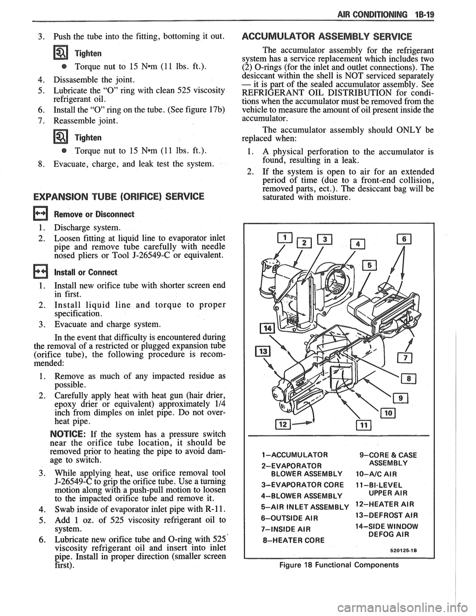
1 -ACCUMULATOR 9-CORE & CASE
2-EVAPORATOR BLOWER ASSEMBLY
10-A/C AIR
3-EVAPORATOR CORE 11-BI-LEVEL
4-BLOWER ASSEMBLY 5-AIR INLET ASSEMBLY
'IR
6-OUTSIDE AIR 13-DEFROST
AIR
7-INSIDE
AIR 14-SIDE WINDOW
DEFOG AIR
8-HEATER CORE
Figure 18 Functional Components
Page 66 of 1825
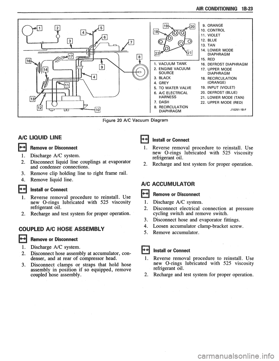
AIR CONDITIONING "18-23
10. CONTROL
14. LOWER MODE
DIAPHRAGM
16. DEFROST DIAPHRAGM
17. UPPER MODE
DIAPHRAGM
18. RECIRCULATION
5. TO WATER VALVE 19. lfVPUT (VIOLET)
6. A/C ELECTRICAL 20. DEFROST (BLUE)
21. LOWER MODE (TAN)
22. UPPER MODE (RED)
8. RECIRCULATION
DIAPHRAGM J~OZ~~-IB-F
Figure 20 AIC Vacuum Diagram
NG LlCbUlB LINE
Remove or Disconnect
1. Discharge A!C system.
2. Disconnect liquid line couplings at evaporator
and condenser connections.
3. Remove clip holding line to right frame rail.
4. Remove liquid line.
lnstall or Conne&
1. Reverse removal procedure to reinstall. Use
new O-rings lubricated with
525 viscosity
refrigerant oil.
2. Recharge and test system for proper operation.
COUPLED NC HOSE ASSEMBLY
Remove or Disconne&
lnstall or Conne&
1. Reverse removal procedure to reinstall. Use
new O-rings lubricated with
525 viscosity
refrigerant oil.
2. Recharge and test system for proper operation.
Remove or Disconnect
1. Discharge A!C system.
2. Disconnect electrical connection at pressure
cycling switch and remove switch.
3. Disconnect hose and evaporator fittings.
4. Loosen accumulator clamp-bracket screw.
5. Remove accumulator.
1. Discharge
NC system.
2. Disconnect hose assembly at accumulator, con- Install or Connect
denser, and at rear of c6mpressor head. 1. Reverse removal procedure to reinstall. Use
3. Disconnect clamps or straps that hold hose new
O-rings lubricated with 525 viscosity
assembly in position if so equipped, remove refrigerant
oil.
coupled hose assembly.
2. Recharge and test system for proper operation.
Page 67 of 1825
1B-24 AIR CONDPTIBNING
EVAPORATOR CORE
Remove QP Disconnect
1. Discharge A/C system.
2. Remove accumulator.
3. Remove two (2) screws and remove hi-blower
relay terminal.
4. Remove upper case screws.
5. Relocate wiring harness and remove dipstick.
6. Disconnect liquid line fitting.
7. Remove upper case and lift evaporator core out
of case (retain foam wedge).
Install or Connect
1. Reverse removal procedure to reinstall.
2. Recharge and test system for proper operation.
EVAPBRAWORCASE
Remove or Disconnect
1. Remove accumulator.
2. Remove blower motor.
3. Remove evaporator core.
Remove lower case to cowl screws (three driven from engine compartment, three driven from
interior).
Remove case from cowl.
Install or Connect
Reverse removal procedure to reinstall. Rein-
stall or replace gaskets, seal and sealant
removed during disassembly.
Recharge and test system for proper operation.
NG COMPRESSOR (TYPICAL)
Remove or Disconnect
1. Discharge A/C system.
2. Remove fitting block (coupled hose assembly)
bolt at rear of compressor.
3. Remove mounting bracket bolt(s) .
4. Remove drive belt (route lower loop behind har-
monic balancer to gain additional slack if
required).
5. Remove compressor. If complete compressor is
to be replaced, transfer usable switches, etc. to
new compressor.
Install or Connect
1. Reverse removal
procedure to reinstall. Use
new O-rings lubricated with
525 viscosity
refrigerant oil. Refer to Section
6B for drive belt
tension.
2. Evacuate and recharge system.
CONDENSER
a Remove or Disconnect
1. Discharge A/C system.
2. Disconnect coupled hose and liquid line fittings.
3, Remove screws retaining top radiator shield.
4. Remove top condenser retaining screws.
5. Carefully move (tilt) radiator rearward and lift
condenser out of radiator support.
6. Transfer brackets and mounts to new condenser
if replacement is necessary.
Install or Connect
1. Reverse removal procedure to reinstall. Use
new O-rings lubricated with
525 viscosity
refrigerant oil.
2. Recharge and test system for proper operation.
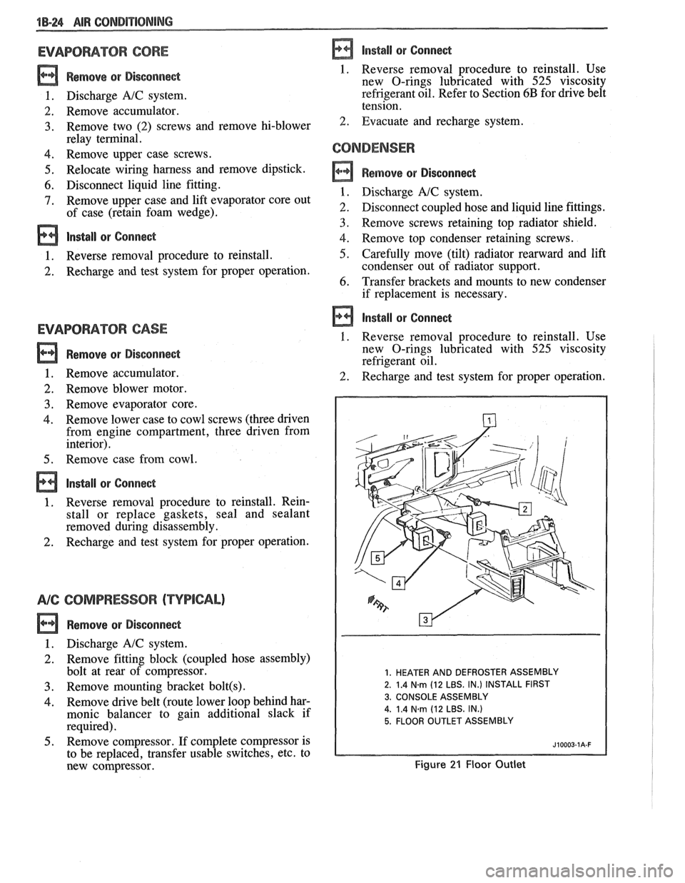
1. HEATER AND DEFROSTER ASSEMBLY
2. 1.4
N.m (12 LBS. IN.) INSTALL FIRST
3. CONSOLE ASSEMBLY
4.
1.4 Narn (12 LBS. IN.)
5. FLOOR OUTLET ASSEMBLY
Figure 21 Floor Outlet
Page 81 of 1825
1 Dl-2 R-4 AIR CONDITIONING COMP
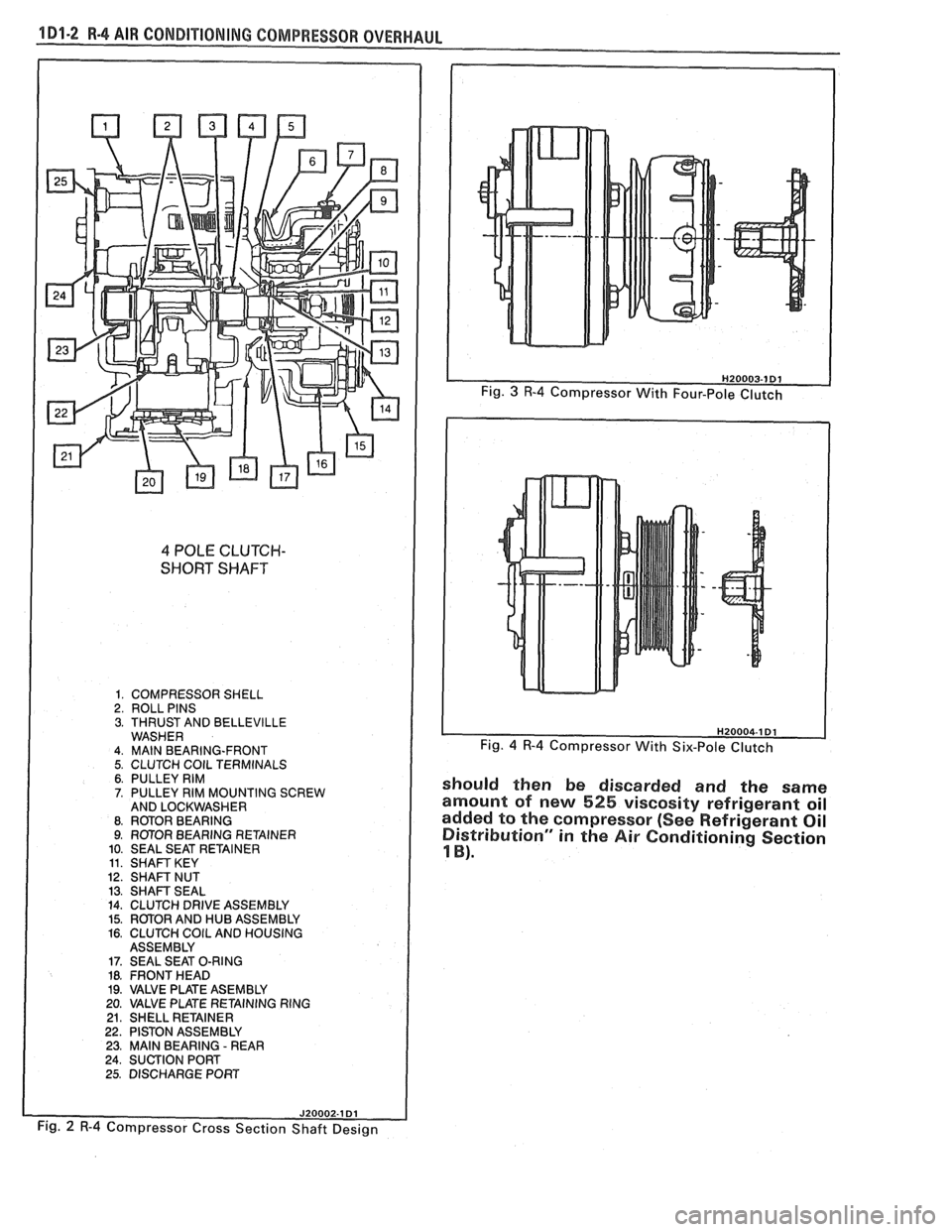
4 POLE CLUTCH-
SHORT SHAFT
1. COMPRESSOR SHELL 2. ROLL PINS 3. THRUST AND BELLEVILLE WASHER 4. MAlN BEARING-FRONT 5. CLUTCH COlL TERMINALS 6. PULLEY RIM 7. PULLEY RIM MOUNTING SCREW
AND LOCKWASHER
8. RmOR BEARING 9. ROTOR BEARING RETAINER
10. SEAL SEAT RETAINER
11. SHAFT KEY 12. SHAFT NUT 13. SHAFT SEAL 14. CLUTCH DRIVE ASSEMBLY 15. ROTOR AND HUB ASSEMBLY 16. CLUTCH COlL AND HOUSING
ASSEMBLY
17. SEAL SEAT O-RING 18. FRONT HEAD 19. VALVE PLATE ASEMBLY
20. VALVE PLATE RETAINING RING
21. SHELL RETAINER 22. PISTON ASSEMBLY 23. MAlN BEARING - REAR 24. SUCTION PORT
25. DISCHARGE PORT
Fig. 4 R-4 Compressor With Six-Pole Clutch
should then be discarded and the same
amount of new
525 viscosity refrigerant oil
added to the compressor (See Refrigerant Oil
Distribution" in
the Air Conditioning Section
1 B).
Fig. 2 R-4 Compressor Cross Section Shaft Design