seat adjustment PONTIAC FIERO 1988 Service Repair Manual
[x] Cancel search | Manufacturer: PONTIAC, Model Year: 1988, Model line: FIERO, Model: PONTIAC FIERO 1988Pages: 1825, PDF Size: 99.44 MB
Page 21 of 1825
OB-4 MAINTENANCE AND LUBRICATION
Tire and wheel operation - Be alert to a vibra-
tion of the steering wheel or seat at normal highway
speeds. This may mean a wheel balance is needed. Also, a
pull right or left on a straight, level road may show the
need for
a tire pressure adjustment or wheel alignment.
Steering system operation - Be alert to
changes in steering action. An inspection is needed when
the steering wheel is harder to turn or has too much free
play or if unusual sounds are noted when turning or
parking.
Headlight aim operation - Take note of light
pattern occasionally. If beam aim doesn't look right,
headlights should be adjusted.
AT EACH FUEL FILL
Engine oil level check - Check engine oil level
and add if necessary. See your Owner's
Manual for further
details.
NOTICE: A large loss in this system may indicate a
problem. Have it inspected and repaired at once.
Engine coolant level and condition - Check
engine coolant level in coolant reservoir tank and add if
necessary. Replace if dirty or rusty. See your Owner's
Manual for further details.
NOTICE: A large loss in this system may indicate a
problem. Have it inspected and repaired at once.
Windshield washer fluid level check -- Check
washer fluid level in container and add if necessary.
Hood latch operation - When opening hood on
cars equipped with hoods that open from the front, note
the operation of secondary latch. It should keep hood from
opening all the way when primary latch is released. Make
sure that hood closes firmly.
AT LEAST MONTI-ILY
Tire and wheel inspection and pressure
check--
Check tires for abnormal wear or damage. Also,
check for damaged wheels. Keep pressures as shown on
Tire Placard on the driver's door (include spare unless it is
a stowaway). Pressure should b\: checked when tires are
"cold". See "Tires" in Owner's Manual for further
infomation.
Light operation check - Check operation of
license plate light, side-marker lights, headlights includ-
ing high beams, parking lights, taillights, brake lights.
turn signals, backup lights, instrument panel and interior
lights and hazard warning flashers.
Fluid leak check - After the car has been parked
for a while, inspect the surface beneath the car for water,
oil, fuel or other fluids. Water dripping from the air
conditioning system after use is normal. If you notice fuel
leaks or fumes, the cause should be found and corrected at
once.
AT LEAST TWICE A YEAR (FOR EXAMPLE,
EVERY SPRING AND FALL)
Power steering pump fluid level check --
Check power steering pump fluid level in accordance with
Owner's Manual instructions and keep at proper level.
NOTICE: A large loss in this system may indicate a
problem. Have it inspected and repaired at once.
Brake master cylinder reservoir fluid level
check ---- Check fluid and keep at proper level. Note: It is
normal for the brake fluid level to go down slightly as the
brake pads wear
- so be sure to keep reservoir filled.
NOTICE: A large loss in this system may indicate a
problem. Have
it inspected and repaired at once.
Clutch system service --- manual transmis-
sionltransaxle --- For cars equipped with hydraulic
clutch system, check the reservoir fluid level and add fluid
as required. All others, check clutch pedal free travel and
adjust as necessary. See your Owner's Manual for further
details.
~
NOTICE: A large loss in this system may indicate a
problem. Have it inspected and repaired at once.
Weatherstrip Lubrication - Clean surface and
then apply a thin film of silicone grease with a clean cloth.
EACH TIME OIL IS CHANGED
Automatic and manual transmissionltrans-
axle fluid level check - Check transmission/transaxle
fluid level and add as required. (Corvette only) if equipped
with manual transmission
- check fluid in the overdrive
unit and add as required.
NOTICE: A large loss in this system may indicate a
problem. Have
it inspected and repaired at once.
Brake systems inspection - For convenience,
the following should be done when wheels are removed
for rotation: Inspect lines and hoses for proper hookup,
binding, leaks, cracks, chafing, etc. Inspect disc brake
pads for wear and rotors for surface condition. Also in-
spect drum brake linings for wear and cracks. Inspect
other brake parts, including drums, wheel cylinders, park-
ing brake, etc. at the same time. Check parking brake
adjustment.
INSPECT BRAKES MORE OFTEN IF DRIVING
HABITS OR CONDITIONS RESULT IN FREQUENT
BRAKING.
Steering, suspension and front drive axle
boot and seal inspection
- Inspect front and rear
suspension and steering system for damaged, loose or
missing parts, signs of wear or lack of lubrication. Inspect
power steering lines and hoses for proper hookup, bind-
ing, leaks, cracks, chafing, etc. (On cars equipped with
manual steering gear, check for seal leakage.) On
front-
wheel-drive cars, clean then inspect drive axle boot seals
for damage, tears or leakage. Replace seals if necessary.
Exhaust system inspection - Inspect complete
system. Inspect body near the exhaust system. Look for
broken, damaged, missing or out-of-position parts as well
as open seams, holes, loose connections or other condi-
tions which could cause a heat buildup in the tloor pan or
could let exhaust fumes seep into the trunk or passenger
compartment.
Page 22 of 1825
MAINTENANCE AND LUBRICATION OB-5
Throttle linkage inspection -- Inspect for inter-
ference, binding, damaged or missing parts.
Engine drive belts inspection - Inspect all
belts for cracks, fraying and wear. Adjust or replace as
needed.
Rear axle service (if equipped) - Check gear
lubricant level and add if needed. For cars equipped with a
limited slip rear axle, fluid does not require changing
(except Caprice and Corvette
- change fluid and required
additive at first
7,500 miles (12 500 km). See your
Owner's Manual or "Recommended Fluids
& Lubricants
Chart" in this section.
IF YOU USE YOUR GAR TO PULL A TRAILER,
CHANGE GEAR LUBRICANT EVERY 7,500 MILES
(12 500 KM).
NOTICE: A large loss in this system may indicate a
problem. Have it inspected and repaired at once.
Power antenna - Clean and then lubricate power
antenna mast. The proper lubricant as shown in Figure
OB-2 should be used.
AT LEAST ONCE A YEAR
Lap and shoulder belts condition and opera-
tion
- Inspect belt system, including webbing, buckles,
latch plates, retractors, guide loops and anchors.
Moveable head restraint operation - On cars
with moveable restraints, make sure restraints stay in the
desired position. (See adjustment instructions in your
Owner's Manual.)
Seatback latch and recliner operation on
cars equipped
with recliner seat --- Be sure seat-
backs latch on those cars with folding seats using mechan-
ical latches. Make sure the recliner is holding by pushing
and pulling on the top of the
seatback while it is reclined.
See your Owner's Manual for seat operating information.
Spare tire and jack storage- Be alert to rattles
in rear of car. Make sure the space tire, all jacking equip-
ment, any tire inflator and any covers or doors are securely
stowed at all times. Oil jack ratchet or screw mechanism
after each use.
Key lock service - Lubricate key lock cylinder at
least annually.
Body lubrication service - Lubricate all body
door hinges including the tailgate or hatchback lid (if
equipped). Also lubricate the body hood, fuel door and
rear compartment hinges and latches including interior
glove box and counsel doors, and any folding seat
hardware.
"Fansmissionltransaxle neutral or clutch
starl switch operation
CAUnON: Before pedorming the follow-
ing safety switch check, be sure to have
enough room around the car. Then, firmly
apply both the parking brake (see your
Owner's Manual for procedure) and the
regular brakes. Do not use the accelerator pedal.
If the engine
starls, be ready to turn
off the ignition promptly. Take these pre-
cautions because the car could move
without warning and possibly cause per-
sonal injury or properly damage. On auto-
matic transmissionltransaxle cars, try to
starl the engine in each gear. The starler
should crank only in "Park" or "Neutral."
On manual transmissionltransaxle cars,
place the
shiR lever in "Neutral," push the
clutch halfway and try to starl. The starler
should crank only when the clutch is fully
depressed.
Steering column lock operation
- While
parked, try to turn key to "Lock" in each gear range. The
key should turn to "Lock" only when gear is in "Park" on
automatic or "Reverse" on manual
transmissionltransax-
le. On cars with key release lever, try to turn key toULock"
without depressing the lever. The key should turn to
"Lock" only with the key lever depressed. On all vehicles,
the key should come out only in "Lock."
Parking brake and transmissionltransaxle
"Park" mechanism operation
CAUT1ON:Before checking the holding
ability of the parking brake and automatic
transmissionltransaxle "Park" mecha-
nism, park on a fairly steep hill with
enough room for movement in the down-
hill direction. To reduce the risk of person-
al injury or property damage, be prepared
to apply the regular brakes promptly if the
car begins to move.
To check the parking brake, with the engine running and
transmission/transaxle in "Neutral." slowly remove foot
pressure from the regular brake pedal (until the car is held
by only the parking brake).
To check the automatic transmissionltransaxle "Park"
mechanism holding ability, release all brakes after shift-
ing the transmissionltransaxle to "Park."
ljnderbody flushing - At least every spring,
tlush from the underbody with plain water any corrosive
materials used for ice and snow removal and dust control.
Take care to thoroughly clean any areas where mud and
other debris can collect.
Sediment packed in closed areas
of the vehicle should be loosened before being flushed.
Engine cooling system service - Inspect
coolant and freeze protection. If dirty or rusty, drain, flush
and refill with new coolant. Keep coolant
at the proper
mixture as specified in your Owner's Manual. This pro-
vides proper freeze protection. corrosion inhibitor level
and engine operating temperature. Inspect hoses and re-
place if cracked. swollen or deteriorated. Tighten hose
clamps. Clean outside of radiator and air conditioning
condensor. Wash radiator filler cap and neck.
To help
ensure proper operation. a pressure test of both the cooling
system and cap is also recommended. (See maintenance
schedule charts in Figure
OB-l for the recommended
coolant change interval.)
Page 29 of 1825
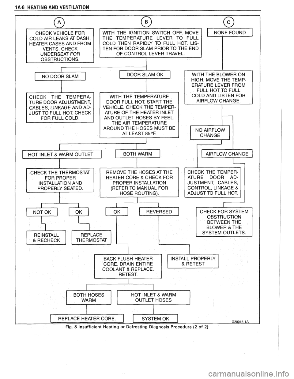
1A-6 HEATING AND VENTILATION
CHECK VEHICLE FOR
COLD AIR LEAKS AT DASH,
HEATER CASES AND FROM
VENTS. CHECK
UNDERSEAT FOR
OBSTRUCTIONS.
w
TEN FOR DOOR SLAM PRIOR TO THE END
CHECK THE TEMPERA-
TURE DOOR ADJUSTMENT,
CABLES, LINKAGE AND AD-
JUST TO FULL HOT. CHECK
I
WITH THE TEMPERATURE
DOOR FULL HOT, START THE
VEHICLE. CHECK THE TEMPER- ATURE OF THE HEATER INLET
AND OUTLET HOSES BY FEEL.
THE AIR TEMPERATURE
AROUND THE HOSES MUST BE AT LEAST
85OF.
I
WITH THE BLOWER ON
HIGH, MOVE THE TEMP-
ERATURE LEVER FROM
FULL HOT TO FULL
COLD AND LISTEN FOR
AIRFLOW CHANGE.
CHECK THE TEMPER-
ATURE DOOR AD-
JUSTMENT, CABLES,
CONTROL, LINKAGE
&
BETWEEN THE
COOLANT REPLACE.
Fig. 8 Insufficient Heating or Defrosting Diagnosis Procedure (2 of 2)
Page 114 of 1825
CHASSIS SHEET METAL 2@-7
3. During the above flash time period (1 to 10 min-
utes), apply appropriate "conventional" interior acrylic lacquer color as required and allow
painted part to dry for
4 to 5 hours before install-
ing on car.
RlGlD OW HARD ABS PMS"TIC PARTS
Rigid or hard ABS plastic requires no primer.
"Conventional" interior acrylic lacquers adhere satis-
factorily to hard ABS plastics.
Procedure
1. Wash part thoroughly with a cleaning solvent
(Acrylic-Clean, Pre-Kleano, Prep-Sol or equiv-
alent) to remove any dirt or grease.
2. Apply appropriate "conventional" interior
acrylic lacquer color. Apply only sufficient
color for proper hiding to avoid washout of
"grain" effect.
3. Allow to dry and then install part.
VINYL AND FLEXIBLE (Son) ABS
PLASTIC PARTS
The outer cover or skin material of "flexible"
instrument panel cover (pad) assemblies is made of an
ABSIPVC plastic blend. The same is true of many
"padded" door trim assemblies. The soft cushion pad-
ding under the I.P. skin is urethane foam plastic. The
most widely used
"flexible" vinyls (poly vinyl chlo-
ride)
are coated fabrics, such as used in seat trim,
some door trim assemblies, molded headlining panels
and sun visors. Most head rests are "flexible" vinyls.
Examples of "hard vinyls are: door and front seat
back assist handles and coat hooks.
The paint system of vinyl and flexible ABS
plastic involves the use of interior "vinyl" color and a
clear vinyl top coat.
Procedure
1. Wash part thoroughly with a vinyl cleaning and
preparation solvent ("Vinyl Press"
- Ditzler,
"Vinyl Prep Conditioner"
- Detroit Autobody
or equivalent) to remove greasy film or silicone.
Wipe off cleaner while still wet with clean,
lint-
free cloth.
2. Immediately after wiping face dry, apply inte-
rior "vinyl" color in wet coats allowing suffi-
cient flash time between coats (see label
directions on can). Use proper "vinyl" color as
designated by interior trim combinations. Apply
only sufficient color for proper hiding to avoid
washout of "grain" effect. No primer or
primer-
sealer is required.
3. Before the final vinyl color coat has dried, apply
two coats of clear vinyl top coat spray (instru-
ment panels will require the "nonglare" clear top
coat). Do not allow the first spray coat to com-
pletely dry before spraying on the second. Use
top coat with appropriate gloss level to match adjacent similar components. This
clear coat is
necessary to control the gloss requirement and
prevent
'tracking" (rubbing-off) of the color
coat after drying.
4. Allow to dry according to label directions before
installing part.
ON-VEHICLE SERVICE
CONCEALED HEADLIGHTS
The concealed headlights used on this model are
electrically operated. When the headlights are turned
on, solid state circuitry activates the actuators. This
same circuitry senses when the actuators stop moving
and removes the ground to deactivate the actuators.
When the headlights are turned off, the actuators run
in opposite direction closing the headlight doors.
Should an electrical failure occur in the head-
light circuit, they may be raised manually by rotating
the knob on the actuator in a counterclockwise direc-
tion until the headlights are fully open. The headlights
may be lowered by rotating the knob on the actuator in
a clockwise direction until the headlights are fully
closed.
For electrical circuit information and diagnosis,
refer to Section
8A of this manual.
If it is desired to raise the headlights with the
lights off, either of the following procedures may be
used:
1. Turn the lights on. After the headlights are
open, disconnect the electrical connections at
the actuator connectors. Turn the lights off. The
headlights will now remain in the open position.
2. Turn the parking lights on. Depress the head-
light rocker switch lightly. The headlights may
then be raised "up" fully with the lights off.
Adjust
Because of the number of adjustments possible
and the number of attaching points of the concealed
headlight body assembly
(9), only those attachments
which control the adjustment desired should be loos-
ened. Make one
adjbstment at a time.
NOTICE: The headlight door does NOT have
slotted mounting holes and therefore is not
adjustable by itself. This insures proper clearance
between the headlight door and the hood and
fenders in both the raised and lowered positions.
The entire headlight body assembly must be
adjusted to achieve the desired appearance and
fit. Care should be exercised when adjusting the
headlight body assembly. Severe hammer blows could damage the die cast aluminum headlight
body assembly.
TO RAISE OR LOWER the headlight body
assembly, proceed as follows:
1. Open hood.
2. Raise headlights.
Page 130 of 1825
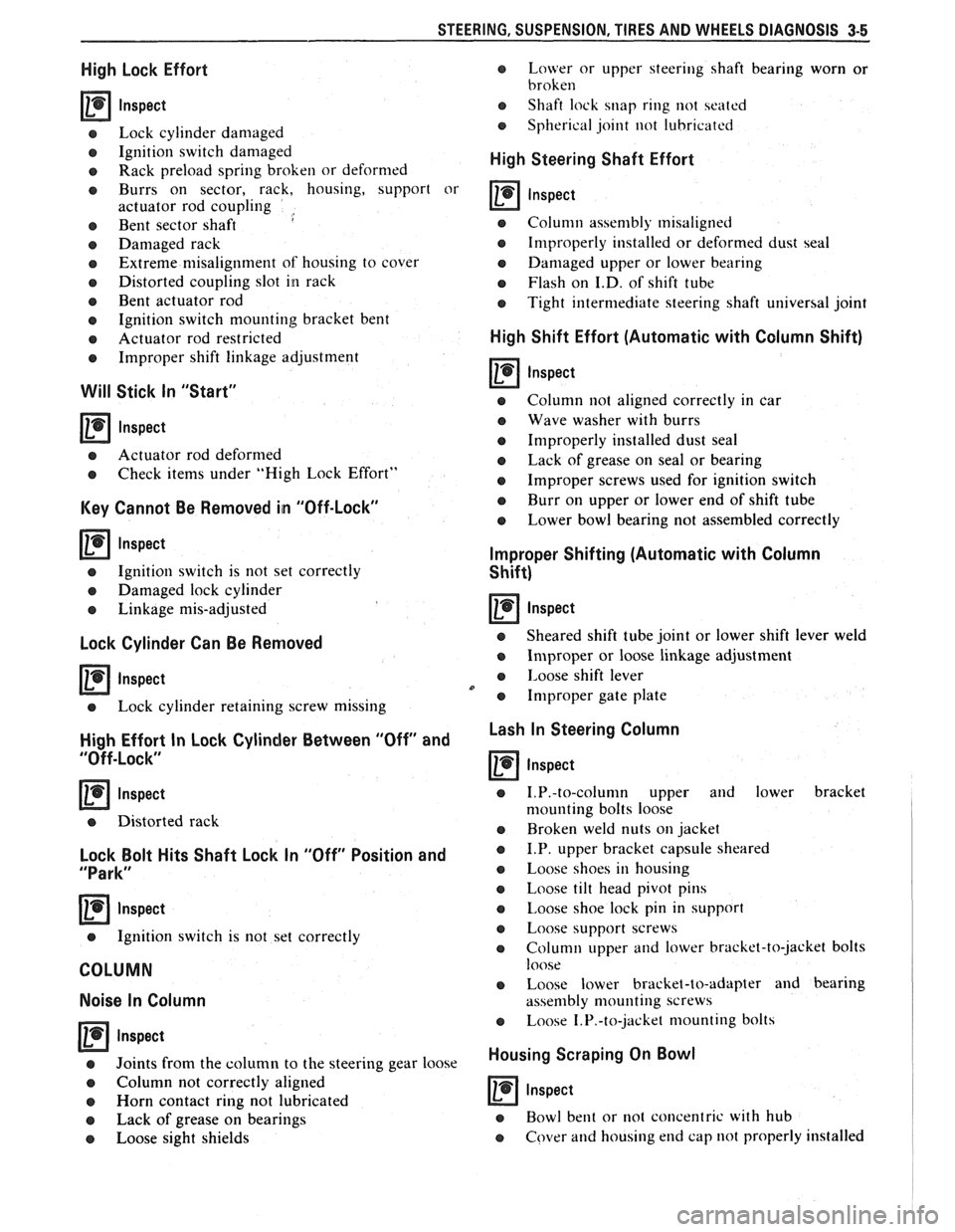
STEERING. SUSPENSION. TIRES AND WHEELS DIAGNOSIS 3-5
High Lock Effort
rn lnspect
e Lock cylinder damaged
e Ignition switch damaged
o Rack preload spring broken or deformed
e Burrs on sector, rack, housing, support or
actuator rod coupling
,
e Bent sector shaft
e Damaged rack
e Extreme misalignment of' housing to cover
e Distorted coupling slot in rack
e Bent actuator rod
e Ignition switch mounting bracket bent
e Actuator rod restricted
e Improper shift linkage adjustment
Will Stick In "Start"
rn lnspect
e Actuator rod deformed
e Check items under "High Lock Effort"
Key Cannot Be Removed in "Off-Lock"
rn lnspect
e Ignition switch is not set correctly
e Damaged lock cylinder
e Linkage mis-adjusted
Lock Cylinder Can Be Removed
Inspect
e Lock cylinder retaining screw missing
High Effort In Lock Cylinder Between "Off" and
"Off-Lock"
lnspect
o Distorted rack
Lock Bolt Hits Shaft Lock In "Off" Position and
"Park"
lnspect
e Ignition switch is not set correctly
COLUMN
Noise In Column
Inspect
e Joints from the column to the steering gear 1
e Column not correctly aligned
e Horn contact ring not lubricated
e Lack of grease on bearings
o Loose sight shields
o Lower or upper steering shaft bearing worn or
broken
e Shaft lock snap ring not seated
o Spherical joint not lubricated
High Steering Shaft Effort
e Column assembly misaligned
e Improperly installed or deformed dust seal
e Damaged upper or lower bearing
e Flash on I.D. of shift tube
e Tight intermediate steering shaft universal joint
High Shift Effort (Automatic with Column Shift)
rn lnspect
e Column not aligned correctly in car
e Wave washer with burrs
e Improperly installed dust seal
o Lack of grease on seal or bearing
e Improper screws used for ignition switch
e Burr on upper or lower end of shift tube
e Lower bowl bearing not assembled correctly
Improper Shifting (Automatic with Column
Shift)
rn lnspect
e Sheared shift tube joint or lower shift lever weld
e Improper or loose linkage adjustment
e 1,oose shift lever
e Improper gate plate
Lash In Steering Column
lnspect
e 1.P.-to-column upper and lower bracket
nlounting bolts loose
e Broken weld nuts on jacket
e I.P. upper bracket capsule sheared
e Loose shoes in housing
e Loose tilt head pivot pins
e Loose shoe lock pin in support
e Loose support screws
e Column upper and lower bracket-to-jacket bolts
loose
e Loose lower bracket-to-adapter and bearing
assembly mounting screws
e Loose 1.P.-to-jacket mounting bolts
Housing Scraping On Bowl
rn Inspect
e Bowl bent or not concentric with hub
e Cover and housing end cap not properly installed
Page 139 of 1825
3-14 STEERING, SUSPENSION, TIRES AND WHEELS DIAGNOSIS
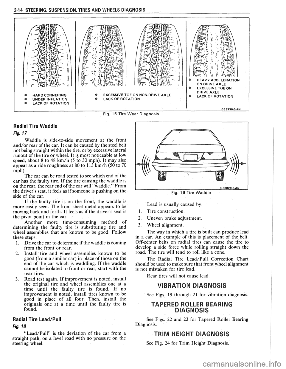
@ HARD CORNERING O UNDER INFLATION LACK OF ROTATION
@ HEAVY ACCELERATION ON DRIVE AXLE EXCESSIVE TOE ON DRIVE AXLE EXCESSIVE TOE ON NON-DRIVE AXLE @ LACK OF ROTATION O LACK. OF ROTAT ION
Fig. 15 Tire Wear Diagnosis
Radial Tire Waddle
Fig. 17
Waddle is side-to-side movement at the front
and/or rear of the car. It can be caused by the steel belt
not being straight within the tire, or by excessive lateral
runout of the tire or wheel. It ig most noticeable at low
speed, about 8 to 48
km/h (5 to 30 mph). It may also
appear as a ride roughness at 80 to 113
km/h (50 to 70
mph). The car can be road tested to see which end of the
car has the faulty tire. If the tire causing the waddle is
on the rear, the rear end of the car will "waddle." From
the driver's seat, it feels as if someone is pushing on the
side of the car.
If the faulty tire is on the front, the waddle is
more easily seen. The front sheet metal appears to be
moving back and forth. It feels as if the driver's seat is
the pivot point in the car.
Another more time-consuming method of
determining the faulty tire is substituting tire and
wheel assemblies that are known to be good. Follow
these steps:
1. Drive the car to determine if the waddle is coming
from the front or rear.
2. Install tire and wheel assemblies known to be
good (from a similar car) in place of those on the
end of the car which is waddling. If the waddle
cannot be isolated to front or rear, start with the
rear tires.
3. Road test again. If improvement is noted, install
the original tire and wheel assemblies one at a
time until the faulty tire is found. If no
improvement is noted, install tires known to be
good in place of all four. Then, install the
originals one at a time until the faulty tire is
found.
Radial Tire Lead/Pull
Fig. 18
"Lead/Pull" is the deviation of the car from a
straight path, on a level road with no pressure
on the
steering wheel.
L Fig. 16 Tire Waddle
Lead is usually caused by:
1. Tire construction.
2. Uneven brake adjustment.
3. Wheel alignment.
The way in which a tire is built can produce lead
in a car. An example of this is placement of the belt.
Off-center belts on radial tires can cause the tire to
develop a side force while rolling straight down the
road. The tire will tend to roll like a cone.
The Radial Tire
Lead/Pull Correction Chart
should be used to make sure that front wheel alignment
is not mistaken for tire lead.
Rear tires will not cause lead.
VIBRATION DIAGNOSIS
See Figs. 19 through 21 for vibration diagnosis.
TAPERED ROLLER BEARING
DlAGNOSlS
See Figs. 22 and 23 for Tapered Roller Bearing
Diagnosis.
See Fig. 24 for Trim Height Diagnosis.
Page 177 of 1825
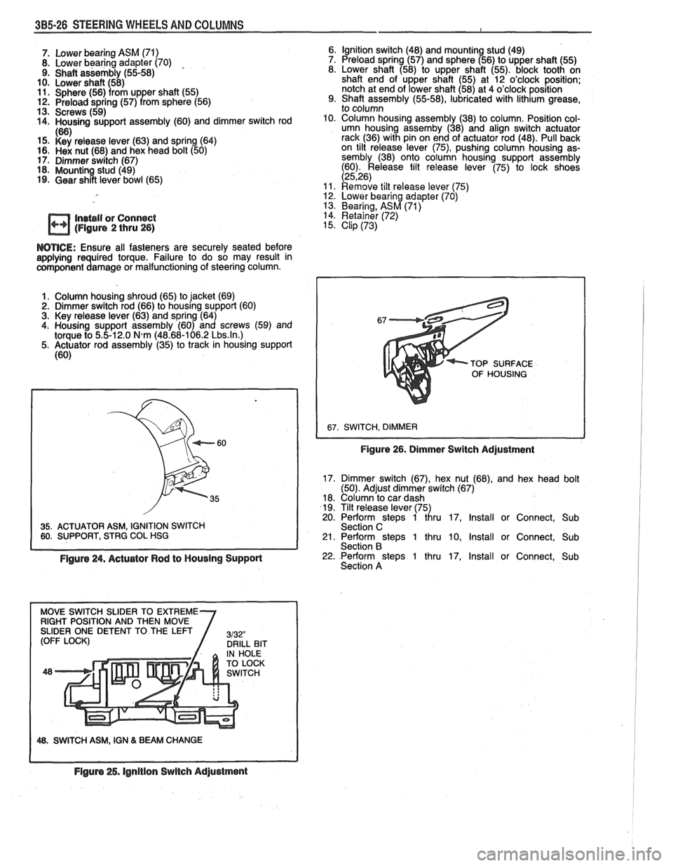
3B5-26 STEERING WHEELS AND COLUMNS
7. Lower bearing ASM (71)
8. Lower bearing adapter (70) - 9. Shaft assembly (55-58)
10. Lower shaft (58)
11. Sphere (56) from upper shaft (55) 12. Preload spring (57) from sphere (56)
13. Screws (59)
14. Housing support assembly (60) and dimmer switch rod
If%
15. i<'si release lever (63) and spring (64) 16. Hex nut (68) and hex head bolt (50)
17. Dimmer switch (67)
18. Mounting stud (49)
19. Gear shift lever bowl (65) Ignition switch (48)
and
mountin stud (49)
Preload spring (57) and sphere 156) to upper shaft (55)
Lower shaft (58) to upper shaft (55). block tooth on
shaft end of upper shaft (55) at 12 o'clock position;
notch at end of lower shaft (58) at 4 o'clock position
Shaft assembly
(55-58), lubricated with lithium grease,
to column
Column housing assembly (38) to column. Position col-
umn housing
assemby (38) and align switch actuator
rack (36) with pin on end of actuator rod (48). Pull back
on tilt release lever
(75), pushing column housing as-
sembly (38) onto column housing support assembly
(60). Release tilt release lever (75) to lock shoes
(2526) Remove tilt release lever 175) 12. Lower bearing adapter (70) '
13. Bearing, ASM (71)
In~bll or Connect 14. Retainer (72)
(Figure 2 thru 26) 15. Clip (73)
WTICE: Ensure all fasteners are securely seated before aaplying required torque. Failure to do so may result in component damage or malfunctioning of steering column.
1. Column housing shroud (65) to jacket (69)
2. Dimmer switch rod (66) to housing support (60)
3. Key release lever (63) and spring (64)
4. Housing support assembly (60) and screws (59) and
torque to
5.5-12.0 N.m (48.68-106.2 Lbs.ln.) 5. Actuator rod assembly (35) to track in housing support
(60)
35. ACTUATOR ASM, IGNITION SWITCH 60. SUPPORT, STRG COL HSG TOP
SURFACE
OF HOUSING
Figure 26. Dimmer Switch Adjustment
17. Dimmer switch (67), hex nut (68), and hex head bolt
(50). Adjust dimmer switch (67)
18. Column to car dash
19. Tilt release lever (75)
20. Perform steps 1 thru 17, Install or Connect, Sub
Section C
21. Perform steps 1 thru 10, Install or Connect, Sub
Section B
Figure 24. Actuator Rod to Housing Support 22. Perform steps 1 thru 17, Install or Connect, Sub
Section A
48. SWITCH ASM, IGN & BEAM CHANGE
Flgure 25. lgnitlon Switch Adjustment
Page 185 of 1825
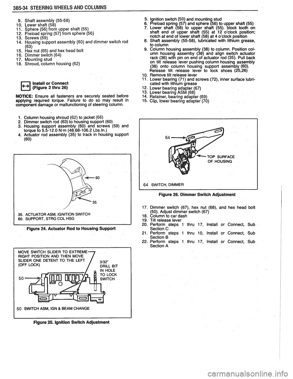
385.34 STEERING WHEELS AND COLUMNS
9. Shaft assembly (55-58)
10. Lower shaft 58)
11. Sphere (56)
I rom upper shaft (55) . 12. Preload spring (57) from sphere (56)
13. Screws (59)
14. Housing support assembly (60) and dimmer switch rod
(63) 15. h& nut (65) and hex head bolt
16. Dimmer switch (64)
17. Mounting stud 18. Shroud, column housing (62)
Insbll or Connect (Flgure 2 thru 26)
WTICE: Ensure all fasteners are securely seated before
applying required torque. Failure to do so may result in
component damage or malfunctioning of steering column.
Column housing shroud (62) to jacket (66)
Dimmer switch rod (63) to housing support (60)
Housing support assembly (60) and screws (59) and
torque to 5.5-12.0
N.m (48.68-106.2 Lbs.ln.) Actuator rod assembly (35) to track in housing support
(60)
35. ACTUATOR ASM, IGNITION SWITCH 60. SUPPORT, STRG COL HSG I
Figure 24. Actuator Rod to Housing Supporl
50 SWITCH ASM, IGN & BEAM CHANGE
5. Ignition switch (50) and mounting stud
6. Preload sprin (57) and sphere (56) to upper shaft (55)
7. Lower shaft
a58) to upper shaft (55). block tooth on
shaft end of upper shaft (55) at 12 o'clock position;
notch at end of lower shaft (58) at 4 o'clock position
8. Shaft assembly
(55-58), lubricated with lithium grease,
to column
9. Column housing assembly (38) to column. Position col-
umn housing assemby (38) and align switch actuator
rack (36) with pin on end of actuator rod (35). Pull back
on tilt release lever pushing column housing assembly
(38) onto column housing support assembly (60).
Release tilt release lever to lock shoes
(2526) 10. Remove tilt release lever 11. Lower bearing (71) and screws (72), inner surface lubri-
cated with lithium grease
12. Lower bearing adapter (67)
13. Lower bearing ASM (68)
14. Retainer, bearing adapter
(69) 15. Clip, lower bearing adapter (70)
TOP SURFACE
OF HOUSING
Figure 26. Dimmer Switch Adjustment
17. Dimmer switch
(67), hex nut (68), and hex head bolt
(50). Adjust dimmer switch (67)
18. Column to car dash
19. Tilt release lever
20. Perform
stem 1 thru 17. Install or Connect. Sub
Section C ' 21. Perform steps 1 thru 10, Install or Connect, Sub
Section B 22. .Perform steps 1 thru 17, Install or Connect, Sub
Section A
Flguro 25. lgnltion Switch Adjustment
Page 212 of 1825
FRONT SUSPENSION 3C-1
SEC"T0RI 3C
FRONT SUSPENS
NOTICE: All front suspension fasteners are an important attaching part in that it could affect the
performance of vital parts and systems, and/or could result in major repair expense. They must be replaced with
one of the same part number or with an equivalent part if replacement becomes necessary. Do not use a
replacement part of lesser quality or substitute design. Torque values must be used as specified during reassembly
to assure proper retention of this part.
NOTICE: Never attempt to heat, quench or straighten any front suspension part. Replace it with a new part
or
damage to the part may result.
CONTENTS
General lnformation ....................................................................................................... 3C-I
On-Car Service ................................................................................................................... 3C- I
Specifications ..................................................................................................................... 3C- 10
GENERAL INFORMATION
The front suspension is designed to allow each
wheel to compensate for changes in the road surface ON-CAR SERVICE
level without appreciably affecting the opposite wheel. WHEEL BEARINGS
Each wheel is independently connected to the frame by
The proper functioning of the front suspension
a steering
kunckle, strut assembly, ball joint, and lower cannot be maintained unless the front wheel tapered arm. The steering in a roller bearings are correctly adjusted. The bearings
prescribed three dimensional arc. The front wheels are
must be a slip fit on the spindle and the inside diameter held in proper relationship to each other by two tie rods of the bearings should be lubricated to insure proper which are connected to steering arms on the knuckles ~h~ spindle nut must be a free-running fit and to the relay rod assembly.
on the threads.
Coil chassis springs are mounted between the
spring housings on the front crossmember and the
lower control arms. Ride control is provided by double,
direct acting strut assemblies. The upper portion of
each strut assembly extends through the fender well
and attaches to the upper mount assembly with a nut.
Side roll of the front suspension is controlled by
a spring steel stabilizer shaft. It is mounted in rubber
bushings which are held to the frame side rails by
brackets. The ends of the stabilizer are connected to the
lower control arms by link bolts and are isolated by
rubber grommets.
The inner ends of the lower control arms have
pressed in bushings. Bolts (passing through the
bushings) attach the arm to the suspension
crossmember. The lower ball joint assembly is a press
fit in the arm and attaches to the steering knuckle with
a torque prevailing nut.
Rubber grease seals are provided at ball socket
assemblies to keep dirt and moisture from entering the
joint and damaging bearing surfaces.
Adjustment
Figure 602
NOTICE: See NOTICE on Page 3C-1
of this
section.
1. Remove dust cap from hub.
2. Remove cotter pin from spindle and spindle nut.
3. Tighten the spindle nut to 16 Nsm (12 lb. ft.)
while turning the wheel assembly forward by
hand to fully seat the bearings. This will remove
any grease or burrs which could cause excessive
wheel bearing play later.
4. Back off the nut to the "just loose" position.
5. Hand tighten the spindle nut. Loosen spindle nut
until either hole in the spindle lines up with a slot
in the nut. Not
nlore than 1/2 flat.
6. Install
new cotter pin. Bend the ends of the cotter
pin against nut, cut off extra length to ensure ends
will not interfere with the dust cap.
7. Measure the looseness in the hub assembly. There
will be
from .03 to . l3mm (.001 to .005 inches)
end play when properly adjusted.
8. Install dust cap on hub.
FRONT SUSPENSION
Refer to Fig. 610 for illustration of attachment
provisions for the bolted-on front suspension
suspension
crossmember.
Page 255 of 1825
4819 REAR AXLE
bears against the inner race of the front bearing and a
shoulder on the pinion stem. This spacer is used to
enable accurate bearing pre-load adjustment and
maintain a pre-load on both front and rear pinion
bearings, Adjustment of the fore and aft position of the
pinion is obtained by placing a shim between the rear
pinion bearing cup and axle housing. The differential
case is of two-piece construction and is supported in
the carrier by two tapered roller side bearings. Pre-load
rear axle case by inserting shims between the bearings
and the carrier. The rear axle case assembly is
positioned for proper ring gear to pinion backlash by
varying the shim thickness from side to side. The ring
gear is bolted to the case. Two side gears have splined
bores for driving the axle shafts. They are positioned
to turn in counterbored cavities in the case. The four
rear axle pinions have smooth bores and are held in
position by a pinion cross shaft, mounted and locked
in the rear axle case. All six gears are in mesh with each
other and because the pinion gears turn freely on their
shaft, they act as idler gears when the rear wheels are
turning at different speeds. The pinions and side gears
are backed by steel thrust washers.
LIMITED-SLIP REAR AXLE
The operation of the Limited-Slip differential is
the same as the standard differential, except that there
is additional friction provided by the conical clutches.
Under ordinary driving and cornering conditions, the
cones slip, allowing the outside wheel to turn faster
than the inner. Under poor traction conditions, such as
ice, snow, or loose gravel under one driving wheel, the
increased friction provided by the cones increases the
driving torque available to the wheel with the better
traction. The cones are spring loaded to provide the
increased driving torque under extremely low traction
conditions.
Operation
When the vehicle turns a corner, the outer rear
wheel must turn faster than the inner wheel. The inner
wheel, turning slower than the outer wheel, slows its
differential side gear (as the axle shaft is splined to the
side gear) and the differential pinion gears will roll
around the slowed differential side gear, driving the
other differential side gear and wheel faster.
DIAGNOSIS AND TESTING
Many noises reported as coming from the rear
axle assembly actually originate from other sources
such as tires, road surfaces, front wheel bearings, axle
bearing, engine, transmission, muffler or body
drumming. A thorough and careful check should be
made to determine the source of the noise before
disassembling the rear axle. Noise which originates in
other places cannot be corrected by adjustment or
replacement of parts in the differential. It should also
be remembered that rear axle gears, like any other
mechanical device, are not absolutely quiet and should
be accepted as being commercially quiet unless some
abnormal noise is present.
To make a systematic check for axle noise under
standard conditions, observe the following:
1. Select a level smooth asphalt road to reduce tire
noise and body drumming.
2. Check rear axle lubricant to assure correct level,
then drive car far enough to thoroughly warm up
rear axle lubricant, approximately 10 miles.
3. Note speed and RPM at which noise occurs. Stop
car and put transmission in neutral. Run engine
slowly up and down through engine speeds,
corresponding to car speed at which noise was
most pronounced, to determine if it is caused by
exhaust, muffler roar or other engine conditions.
4. Tire noise changes with different road surfaces,
but rear axle noise does not. Temporarily
inflating all tires to approximately 50 pounds
pressure
for test purposes only will materially
alter noise caused by tires, but will not affect noise
caused by rear axle. Rear axle noise usually stops
when coasting at speeds under 30 miles per hour;
however, tire noise continues, but with lower
tone, as car speed is reduced. Rear axle noise
usually changes when comparing acceleration
and coast, but tire noise remains about the same.
Distinguish between tire noise and rear axle noise
by noting if noise varies with various speeds or
sudden acceleration and deceleration; exhaust
and axle noise show variations under these
conditions while tire noise remains constant and
is more pronounced at speeds of 20 to 30 miles
per hour. Further check for tire noise by driving
car over smooth pavements or dirt roads (not
gravel) with tires at normal pressure. If noise is
caused by tires, it will noticeably change or
disappear and reappear with changes in road
surface.
5. Loose or rough front wheel bearings will cause
noise which may be confused with rear axle
noises; however, front wheel bearing noise does
not change when comparing drive and coast.
Light application of brakes while holding car
speed steady will often cause wheel bearing noise
to diminish, as this takes some weight off the
bearing. Front wheel bearings may be easily
checked for noise by jacking up the wheels and
spinning them, also by shaking wheels to
determine if bearings are loose.
6. Rear suspension rubber bushings and spring
insulators dampen out rear axle noise when
correctly installed. Check to see that no metallic
contact exists between the spring and spring seat
opening in frame or between upper and lower
control arm bushings and frame or axle housing
brackets. The track bar and torque arm must be
bolted securely. Metal-to-metal contact at those
points may result in telegraphing road noise and
normal axle noise which would not be
objectionable if dampened by bushings.
AXLE NOISES
After the noise has been determined as being in
the axle by following the above appraisal procedure,
the type of axle noise should be determined to aid in
making repairs if necessary.