overheating PONTIAC FIERO 1988 Service Repair Manual
[x] Cancel search | Manufacturer: PONTIAC, Model Year: 1988, Model line: FIERO, Model: PONTIAC FIERO 1988Pages: 1825, PDF Size: 99.44 MB
Page 20 of 1825
F CARLINE
ITEM 10
TransmissionRransaxle Service
The manual transmission or transaxle fluid does not
require changing. (Corvette only.) Change fluid in over-
drive unit every 30,000 miles (50 000 km).
For automatic transmissions or transaxles, change
both the fluid and filter every 15,000 miles (25 000 km) if
the car is mainly driven under one or more of these
conditions:
@ In heavy city traffic where the outside temperature
regularly reaches 90°F (32°C) or higher.
@ In hilly or mountainous terrain.
@ Frequent trailer pulling.
@ Uses such as found in taxi, police car or delivery
service.
If you do not use your car under any of these condi-
tions, change both the fluid and filter every 100,000 miles
(160 000 km). See you Owner's Manual for further
details.
ITEM 11
Spark Plug Service*
Replace spark plugs with type listed in your Owner's
Manual.
ITEM 12
Spark Plug Wire Inspection*
Clean wires and inspect for burns, cracks or other dam-
age. Check the wire boot fit at distributor and at spark plugs.
Replace wires as needed.
ITEM 13
Positive Crankcase Ventilation (PCV) Valve
Inspection*
Inspect valve for proper function. Replace valve if
necessary as well as any worn, plugged or collapsed
hoses.
ITEM 14
EGR System Service*
Conduct EGR System Service as referenced in the
EGR System Chart shown in the appropriate 6E Section.
Also, refer to your GM maintenance schedule booklet for
specific applications.
ITEM 15
Air Cleaner and PCV Filter Replacement*
On 1.6 and 2.0 liter engines, replace every 50,000
miles (80 000 km). On all other engines, replace every
30,000 miles (50 000 km). Replace more often under
dusty conditions. Ask your dealer for the proper replace-
ment interval for your driving conditions.
MAINTENANCE AND LUBRICATION 08-3
ITEM 16
Engine Timing Check*
Adjust timing to underhood label specifications. If
no specifications are shown, no adjustment is needed.
ITEM 17
Fuel Tank, Cap and Lines Inspection*
Inspect fuel tank, cap and lines (including fuel rails
and injection assembly, if so equipped) for damage or
leaks. Inspect fuel cap gasket for an even filler neck
imprint or any damage. Replace parts as needed.
ITEM 18
Thermostatically Controlled Air Cleaner
Inspection*
If your car is equipped, inspect all hoses and ducts
for proper hookup. Make sure valve works properly.
OWNER INSPECTIONS AND SERVICES
Listed below are inspections and services which
should be made by either you or a qualified technician at
the intervals shown to help ensure proper safety, emission
performance and dependability of your car. Take any
problems promptly to your dealer or another qualified
technician for service advice. Whenever repairs are neces-
sary, have them completed at once. For your safety and
that of others, any safety-related parts that could have
been damaged in an accident should be inspected and all
needed repairs should be done before operating your car.
Be sure to use the proper fluids and lubricants as shown in
Figure OB-2.
WHILE OPERATING YOUR VEHICLE
Automatic transmissionltransaxle shift indi-
cator operation - Make sure the indicator points to the
gear chosen.
Horn operation - Blow the horn occasionally to
make sure it works. Check all button locations.
I
Brake system operation -- Be alert to abnormal
sounds, increased brake pedal travel or repeated pulling to
one side when braking. Also, if a brake warning light
comes on or flashes, or the anti-lock warning light (if
equipped) comes on or remains on, something may be
wrong with part of the brake system. Have it inspected and
repaired at once.
Exhaust system operation - Be alert to any
changes in the sound of the system or any smell of fumes.
These are signs the system may be leaking or overheating.
.
Have it inspected and repaired at once. Also see "Engine
Exhaust Gas Caution (Carbon Monoxide)" and "Catalytic
Converter" in your Owner's Manual.
*An Emission Control Service
Page 145 of 1825
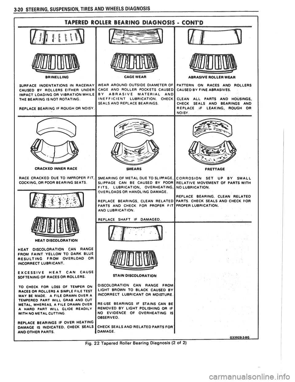
BRINELLING
SURFACE INDENTATIONS IN RACEWAY
CAUSED BY ROLLERS EITHER UNDER
IMPACT LOADING OR VIBRATION WHILE
THE BEARING IS NOT ROTATING.
REPLACE BEARING IF ROUGH OR NOISY. CAGE WEAR
WEAR AROUND OUTSIDE DIAMETER OF
CAGE AND ROLLER POCKETS CAUSED
BY ABRASIVE MATERIAL AND
INE FF IClENT LUBRICATION CHECK
SEALS AND REPLACE BEARINGS. ABRASIVE
ROLLER WEAR
PATTERN ON RACES AND ROLLERS
CAUSED BY
FINE ABRASIVES.
CLEAN ALL PARTS AND HOUSINGS,
CHECK SEALS AND BEARINGS AND
REPLACE IF LEAKING, ROUGH
OR NOISY
CRACKED INNER RACE
WEARS FRETfAGE
RACE CRACKED DUE TO IMPROPER FIT, SMEARING OF METAL DUE TO SLIPBAGE, CORROSION SET UP BY SMALL
COCKING. OR POOR BEARING SEATS. SLIPPAGE CAN BE CAUSED BY POOR RELATIVE MOVEMENT OF PARTS WITH I F ITS. LUBRICATION, OVERHEATING,
OVERLOADS OR HANDLING DAMAGE
REPLACE BEARING. CLEAN RELATED
REPLACE BEARINGS, CLEAN RELATED
PARTS AND CHECK FOR PROPER FIT
I AND LUBRICATION. I I
HEAT DISCOLORATION CAN RANGE
FROM FAINT YELLOW TO DARK BLUE
RESULTING FROM OVERLOAD OR
INCORRECT LUBRICANT.
EXCESSIVE HEAT CAN CAUSE
SOFTENING OF RACES
OR ROLLERS.
TO CHECK FOR LOSS OF TEMPER ON
RACES OR ROLLERS A SIMPLE
FlLE TEST MAY BE MADE. A FILE DRAWN OVER A
TEMPERED PART WlLL GRAB AND CUT
METAL. WHEREAS, A FlLE DRAWN OVER
A HARD PART WlLL GLIDE READILY WlTH NO METAL CUTTING
REPLACE BEARINGS IF OVER HEATING
DAMAGE IS INDICATED. CHECK SEALS
AND OTHER PARTS.
mAIN DISCOLORATION
I DISCOLORATION CAN RANGE FROM
LIGHT BROWN TO BLACK CAUSED BY
INCORRECT LUBRICANT OR MOISTURE.
RE-USE BEARINGS IF STAINS CAN BE
REMOVED BY LIGHT POLISHING OR IF
NO EVIDENCE OF OVERHEATING IS
OBSERVED.
CHECK SEALS AND RELATED PARTS FOR
DAMAGE.
Page 245 of 1825
4A-4 PROPELLER SHAFT
PROPELLER SHAFT BALANCING
Hose Clamp Method
Figures 4A- 1 1 thru 4A-13
1. Place the vehicle on a twin post hoist so that the
rear of the vehicle is supported on the rear axle
housing and the rear wheels are free to rotate.
Remove both rear wheel assemblies and reinstall
wheel lug nuts with flat sides next to
drums/discs.
2. Mark and number propeller shaft at four (4)
points 90 degrees apart at rear of shaft just
forward of balance weight, as shown.
3. Install two (2) hose clamps on the rear of the
propeller shaft and slide them rearward until the
clamps stop at the nearest balance weight welded
to the tube. Align both clamps at any one of the
four marks made on shaft in Step 2 and tighten.
Be sure sufficient clearance is maintained so that
clamp heads do not contact floor pan of vehicle
when axle is in contact with rebound bumper in
frame. In order to gain sufficient clearance, it
may be necessary to position the clamps over the
balance weights.
4. Run the vehicle through the speed range to 80-90
MPH (130-145
Km/h) and note amount of
imbalance.
CAUTION: All persons should stay
clear of universal joint and balance
weight areas to avoid possible injury.
Do not run on hoist for extended
periods due to the danger of
overheating the transmission or
engine.
5. Loosen clamps and rotate clamp heads 90 degrees
to the next mark on a propeller shaft. Tighten
clamps and repeat Step 4.
6. Repeat Step 5 until car has been run with clamp
heads located at all four marks on shaft.
7. Position clamps at point of least imbalance.
Rotate the clamp heads away from each other 45
degrees (one on each side of the position), as
shown. Run the vehicle and note if imbalance has
improved.
In some cases it may be necessary to use one
clamp or possibly three clamps in order to obtain
a good balance. Replace shaft if three hose clamps
do not improve the imbalance.
8. Continue to rotate the clamps apart in smaller
angular increments until the imbalance is at its
minimum.
9. Reinstall wheel assemblies and road test the
vehicle for final check of balance. A minimal
vibration felt in the vehicle on the hoist may not
show up during a road test.
Strobe Light Method
Figures 461- 1 1, $A- 14, and 4A- 15
If a wheel balancer of the strobe light type is
available, the use of such a unit will facilitate the
balancing of the propeller shaft. The balance pick-up
unit should be placed directly under the nose of the
rear axle carrier and as far forward as possible. 1.
Place
the vehicle on a twin post hoist so the rear of
the vehicle is supported on the rear axle housing and
the rear wheels are free to rotate. Lower rear hoist
and allow axle to rest on jackstands. The groove in
the rear hoist fixture could clamp the axle and de-
stroy the sensitivity of the operation. Remove both
rear wheel assemblies and reinstall wheel lug nuts
with flat sides next to the
drums/rotors.
2.
Mark and number drive shaft at 4 points 90
degrees apart at rear of shaft just forward of
balance weights, as shown.
3. Place the strobe light wheel balancer pick-up
under the nose of the carrier.
4. Run vehicle in gear at the speed where the
distrubance is at its peak, allow the driveline to
stabilize by holding at a constant speed. Point
strobe light up at the spinning propeller shaft and
note position of one of the reference numbers.
Shut off engine and position the propeller shaft so
the reference numbers will be in the same position
as was noted while the shaft was rotating.
When strobe light flashed, the heaviest point of
the shaft was at the bottom (6 o'clock). To
balance the propeller shaft, it would be necessary
to apply the balancing weights (hose clamps) 180
degrees away from the heaviest point or at the top
of the propeller shaft (12 o'clock).
5. Install two screw-type hose clamps on the
propeller shaft as close to the rear as possible.
Position both clamp heads 180 degrees from the
heaviest point of drive shaft as indicated by strobe
light. Tighten clamps.
NOTICE: Be sure sufficient clearance is
maintained so clamp heads do not contact floor
pan of vehicle when axle is in contact with rebound
bumper on frame. In order to gain. sufficient
clearance, it may be necessary to position the
clamps over the balance weights.
6. Run vehicle through the speed range 80-90
M.P.
H. (130-145 Km/h). If disturbance is gone,
nothing further need be done on the hoist. If the
disturbance is not gone and the strobe light shows
the clamp heads at the bottom (6 o'clock) of the
shaft, go to Step
7. If the strobe light shows the
two clamp heads at the top of the shaft, add one
more hose clamp and recheck. If the strobe light
shows the three clamp heads at the top of the
shaft, remove the propeller shaft and
reindex it
180 degrees on the rear axle pinion companion
flange. Recheck with no clamps. Repeat balance
starting with Step 5. If the shaft still needs more
than three hose clamps at the same clock position,
replace it. If the clamps are also 180 degrees from
their original position after the propeller shaft
was reindexed 180 degrees, the rear axle pinion
companion flange is out of balance and must be
replaced. DO NOT use more than three hose
clamps to balance the shaft. If the strobe light
shows the hose clamps at the bottom of the shaft,
but the disturbance still exists, go to Step
7.
Page 259 of 1825
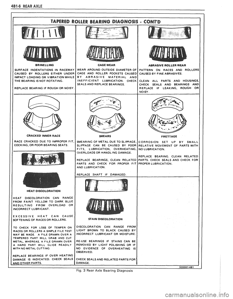
4B1-6 REAR AXLE
THE BEARING IS NOT ROTATING.
SEALS AND REPLACE BEARINGS. CHECK SEALS AND BEARINGS AND
CRACKED INNER RACE
F R ETTAGE
OVERLOADS OR HANDLING DAMAGE.
AND LUBRICATION.
HEAT DISCOLORATION CAN RANGE
FROM FAINT YELLOW TO DARK BLUE
RESULTING FROM OVERLOAD OR
INCORRECT LUBRICANT.
EXCESSIVE HEAT CAN CAUSE
SOFTENING OF RACES OR ROLLERS.
STAIN DISCOLORATION
TEMPERED PART
WILL GRAB AND CUT
WITH NO METAL CUTTING. NO EVIDENCE OF OVERHEATING IS
Fig. 3 Rear Axle Bearing Diagnosis
Page 278 of 1825
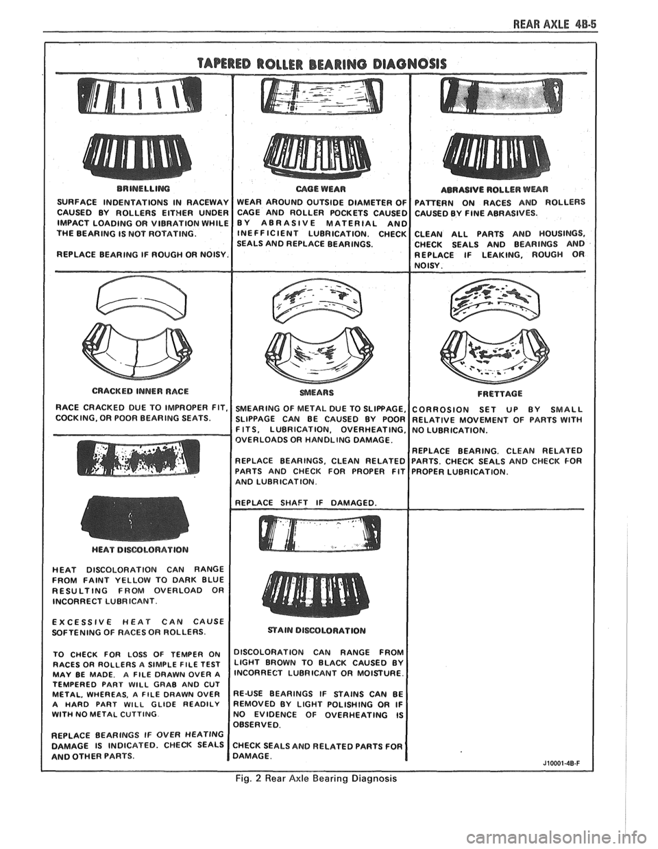
REAR AXLE 48-5
BRINELLIM
SURFACE INDENTATIONS IN RACEWAY
CAUSED BY ROLLERS EITHER UNDER
IMPACT LOADING OR VIBRATION WHILE
THE BEARING IS NOT ROTATING.
REPLACE BEARING IF ROUGH OR NOISY.
I
CRACKED INNER RACE
RACE CRACKED DUE TO IMPROPER FIT,
COCKING, OR POOR BEARING SEATS.
mOE WEAR
WEAR AROUND OUTSIDE DIAMETER OF
CAGE AND ROLLER POCKETS CAUSEC
BY ABRASIVE MATERIAL
AN0 INEFFICIENT LUBRICATION. CHECK
SEALS AND REPLACE BEARINGS.
SMEARING OF METAL DUE TO SLIPPAGE,
SLIPPAGE CAN BE CAUSED BY POOR
F ITS, LUBRICATION, OVERHEATING,
OVERLOADS OR HANDLING DAMAGE.
REPLACE BEARINGS. CLEAN RELATED
PARTS AND CHECK FOR PROPER FIT
AND LUBRICATION. ABRASIVE
ROLLER
WUR
PAmERN ON RACES AND ROLLERS
CAUSED BY FINE ABRASIVES.
CLEAN ALL PARTS AND HOUSINGS,
CHECK SEALS AND BEARINGS AND
REPLACE IF LEAKING, ROUGH
OR NOISY.
FRETTACE
CORROSION SET UP BY SMALL
RELATIVE MOVEMENT OF PARTS WlTH
NO LUBRICATION.
REPLACE BEARING. CLEAN RELATED
PARTS. CHECK SEALS AND CHECK FOR
PROPER LUBRICATION.
HEAT DISCOLORATION CAN RANGE
FROM FAINT YELLOW TO DARK BLUE
RESULTING FROM OVERLOAD OR
INCORRECT LUBRICANT.
EXCESSIVE
HEAT CAN CAUSE
SOFTENING OF RACES OR ROLLERS.
TO CHECK FOR LOSS OF TEMPER ON
DISCOLORATION CAN RANGE FFmM RACES OR ROLLERS A SIMPLE FILE TEST LIGHT BROWN TO BLACK CAUSED BY MAY BE MADE. A FILE DRAWN OVER A lNCORRECT LUBRICANT OR MOISTURE.
TEMPERED PART
WlLL GRAB AND CUT METAL, WHEREAS. A FILE DRAWN OVER RE-USE BEARINGS IF STAINS CAN BE
A HARD PART WILL GLIDE READILY REMOVED BY LIGHT POLISHING OR IF WITH NO METAL CUTTING NO EVIDENCE OF OVERHEATING IS
OBSERVED.
REPLACE BEARINGS IF OVER
HEATING
DAMAGE IS INDICATED. CHECK SEALS CHECK SEALS AND RELATED PARTS FOR
AND OTHER PARTS. DAMAGE.
J10001-40-F
Fig. 2 Rear Axle Bearing Diagnosis
Page 415 of 1825
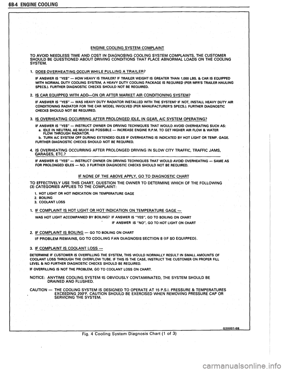
BB.4 ENGINE COOLING
ENGINE COOLING SYSTEM COMPLAINT
TO AVOID NEEDLESS
TIME AND COST IN DIAGNOSING COOLING SYSTEM COMPLAINTS, THE CUSTOMER
SHOULD BE QUESTIONED ABOUT DRIVING CONDITIONS THAT PLACE ABNORMAL LOADS ON THE COOLING
SYSTEM.
1. DOES OVERHEATING OCCUR WHILE PULLING A TRAILER?
IF ANSWER IS "YES'- HOW HEAVY IS TRAILER? IF TRAILER WEIGHT IS GREATER THAN 1,000 LBS. & CAR IS EQUIPPED
WITH NORMAL DUTY COOLING SYSTEM, A HEAVY DUTY COOLING PACKAGE IS REQUIRED (PER MFR'S TRAILER HAULING
SPECS.). FURTHER DIAGNOSTIC CHECKS SHOULD NOT BE REQUIRED.
2. IS CAR EQUIPPED WlTH ADD-ON OR AFTER MARKET AIR CONDITIONING SYSTEM?
IF ANSWER IS "YES"- WAS HEAVY DUTY RADIATOR INSTALLED WITH THE SYSTEM? IF NOT, INSTALL HEAVY DUTY AIR
CONDITIONING RADIATOR FOR THE CAR MODEL INVOLVED (PER MANUFACTURER'S SPECS.). FURTHER DlAGNOSTlC
CHECKS SHOULD NOT BE REQUIRED.
3. IS OVERHEATING OCCURRING AFTER PROLONGED IDLE, IN GEAR, AIC SYSTEM OPERATING?
IF ANSWER IS "YES - INSTRUCT OWNER ON DRIVING TECHNIQUES THAT WOULD AVOID OVERHEATING SUCH AS: a, IDLE IN NEUTRAL AS MUCH AS POSSIBLE - INCREASE ENGINE R.P.M. TO GET HIGHER AIR FLOW & WATER
FLOW THROUGH RADIATOR.
b. TURN A/C SYSTEM OFF DURING EXTENDED IDLES IF OVERHEATING IS INDICATED BY HOT LIGHT OR TEMP. GAGE.
FURTHER DIAGNOSTIC CHECKS SHOULD NOT BE REQUIRED.
4. IS OVERHEATING OCCURRING AFTER PROLONGED DRIVING IN SLOW CITY TRAFFIC, TRAFFIC JAMS,
GARAGES, ETC.?
IF ANSWER IS "YES - INSTRUCT OWNER ON DRIVING TECHNIQUES THAT WOULD AVOID OVERHEATING - SAME AS
FOR PROLONGED IDLES - NO. 3 FURTHER DIAGNOSTIC CHECKS SHOULD NOT BE REQUIRED.
IF NONE OF THE ABOVE APPLY, GO TO DIAGNOSTIC CHART
TO EFFECTIVELY USE THlS CHART, QUESTION THE OWNER TO DETERMINE WHICH OF THE FOLLOWING
(3) CATEGORIES APPLIES TO THE COMPLAINT:
1. HOT LlGHT OR HOT INDICATION ON TEMPERATURE GAGE 2. BOILING 3. COOLANT LOSS
1. IF COMPLAINT IS HOT LlGHT OR HOT INDICATION ON TEMPERATURE GAGE -
WAS HOT LlGHT ACCOMPANIED BY BOILING? IF ANSWER IS "YES", GO TO BOILING ON CHART
IF ANSWER IS "NO, GO TO HOT LlGHT ON CHART
2. IF COMPLAINT IS BOILING - GO TO BOILING ON CHART
IF PROBLEM REMAINS, GO TO COOLING
FAN DIAGNOSIS SECTION 8 (IF SO EQUIPPED).
I 3. IF COMPLAINT IS COOLANT LOSS -
DETERMINE IF CUSTOMER IS OVERFILLING THE SYSTEM, THlS WOULD NORMALLY RESULT IN SMALL AMOUNTS OF
I COOLANT LOSS THROUGH THE OVERFLOW TUBE. IF THlS IS THE CASE, INSTRUCT THE CUSTOMER ON PROPER FILL LEVEL & NO FURTHER DIAGNOSTIC CHECKS SHOULD BE REQUIRED.
I IF OVERFILLING IS NOT THE PROBLEM, GO TO COOLANT LOSS ON CHART.
NOTICE:
ANYTIME COOLING SYSTEM IS OBVIOUSLY CONTAMINATED, THE SYSTEM SHOULD BE
DRAINED AND FLUSHED.
1 CAUTION - THE COOLING SYSTEM IS DESIGNED TO OPERATE AT 15 P.S.I. PRESSURE & TEMPERATURES
EXCEEDING 200°F. CAUTION SHOULD BE EXERCISED WHEN REMOVING PRESSURE CAP OR
I SERVICING THE SYSTEM.
Fig. 4 Cooling System Diagnosis Chart (I of 3)
Page 417 of 1825
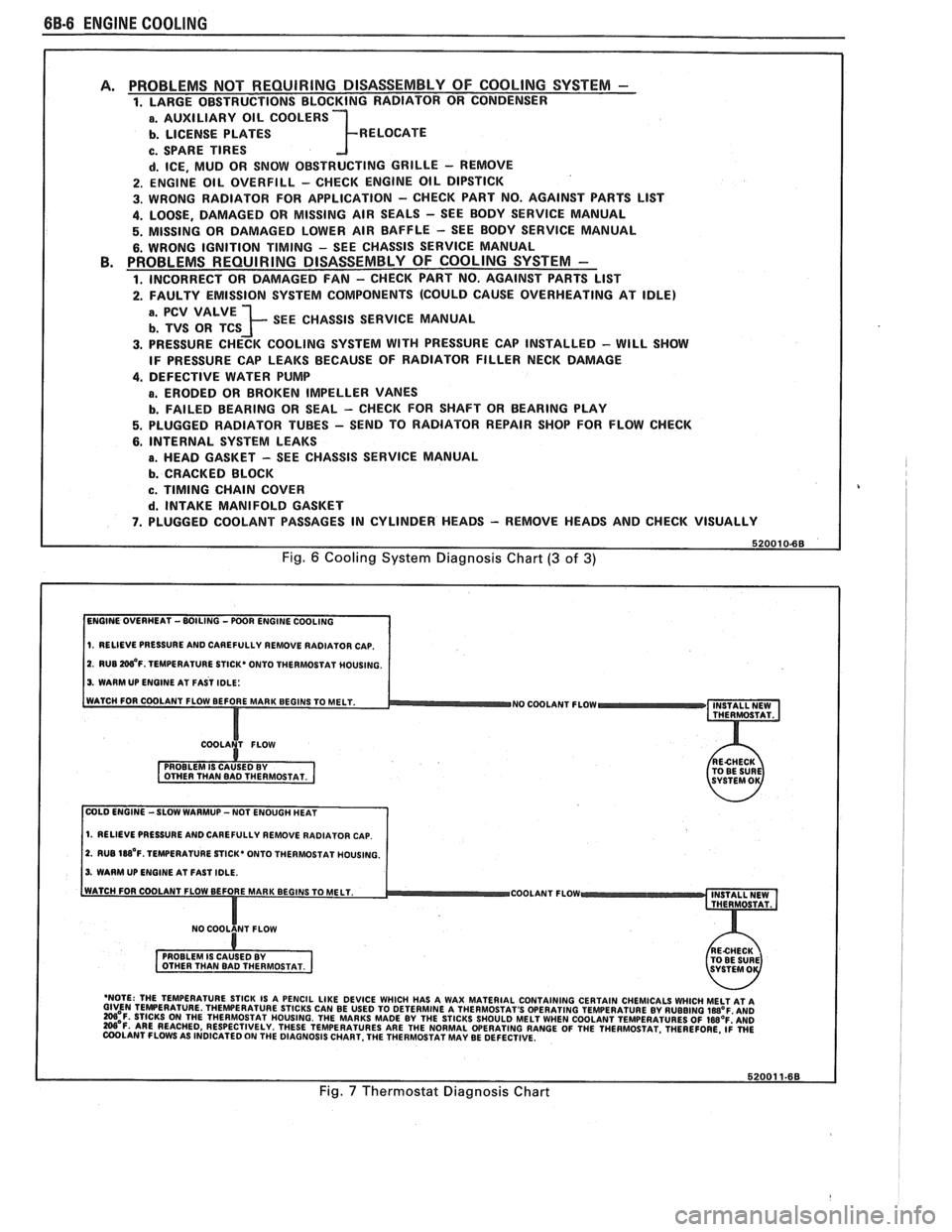
6B-8 ENGINE COOLING
PROBLEMS NOT REQUIRING DISASSEMBLY OF COOLING SYSTEM - 1. LARGE OBSTRUCTIONS BLOCKING RADIATOR OR CONDENSER
a. AUXILIARY OIL COOLERS
b. LICENSE PLATES R ELOCATE
c. SPARE TIRES
d. ICE, MUD OR SNOW OBSTRUCTING GRILLE - REMOVE
2. ENGINE OIL OVERFILL - CHECK ENGINE OIL DIPSTICK
3. WRONG RADIATOR FOR
APPLICATION - CHECK PART NO. AGAINST PARTS LlST
4. LOOSE, DAMAGED OR MISSING AIR SEALS - SEE BODY SERVICE MANUAL
5. MISSING OR DAMAGED LOWER AIR BAFFLE - SEE BODY SERVICE MANUAL
6. WRONG IGNITION TIMING - SEE CHASSIS SERVICE MANUAL PROBLEMS REQUIRING DISASSEMBLY OF COOLING SYSTEM -
1. INCORRECT OR DAMAGED FAN - CHECK PART NO. AGAINST PARTS LlST
2. FAULTY EMISSION SYSTEM COMPONENTS (COULD CAUSE OVERHEATING AT IDLE)
; SEE CHASSIS SERVICE MANUAL
3. PRESSURE CHECK COOLING SYSTEM WITH PRESSURE CAP INSTALLED - WILL SHOW
IF PRESSURE CAP LEAKS BECAUSE OF RADIATOR FILLER NECK DAMAGE
4. DEFECTIVE WATER PUMP
a. ERODED OR BROKEN IMPELLER VANES
b. FAILED BEARING OR SEAL - CHECK FOR SHAFT OR BEARING PLAY
5. PLUGGED RADIATOR TUBES - SEND TO RADIATOR REPAIR SHOP FOR FLOW CHECK
6. INTERNAL SYSTEM LEAKS
B. HEAD GASKET - SEE CHASSIS SERVICE MANUAL
b. CRACKED BLOCK
c. TIMING CHAIN COVER
d. INTAKE MANIFOLD GASKET
7. PLUGGED COOLANT PASSAGES IN CYLINDER HEADS - REMOVE HEADS AND CHECK VISUALLY
Fig. 6 Cooling System Diagnosis Chart (3 of 3)
1. RELIEVE PRESSURE AND CAREFULLY REMOVE RADIATOR CAP.
2. RUB W'F. TEMPERATURE STICK* ONTO THERMOSTAT MOUSING.
3. WARM UP ENGINE AT FAST IDLE:
WATCH FOR COOLANT FLOW BEFORE MAR
NO COOLANT FLOW INSTALL NEW
THERMOSTAT.
COLD ENGINE -SLOW WARMUP -NOT ENOUGH HEAT
1. RELIEVE PRESSURE AND CAREFULLY REMOVE RADIATOR CAP.
2. RUB 188'~. TEMPERATURE STICK' ONTO THERMOSTAT HOUSING.
3. WARM UP ENGINE AT FAST IDLE.
COOLANT FLOW
- 'NOTE: THE TEMPERATURE STICK IS A PENCIL LIKE DEVICE WHICH HAS A WAX MATERIAL CONTAINING CERTAIN CHEMICALS WHICH MELT AT A GIVEN TEMPERATURE THEWERATURE STICKS CAN BE USED TO DETERMINE A THERMOSTAT'S OPERATING TEMPERATURE BY RUBBING laB°F AN0 =OF. STICKS ON THE THERMOSTAT HOUSING. THE MARKS MADE BY THE STICKS SHOULD MELT WHEN COOLANT TEMPERATURES OF IWOF'AND W'F. ARE REACHED, RESPECTIVELY. THESE TEMPERATURES ARE THE NORMAL WERATING RANGE OF THE THERMOSTAT. THEREFORE, ~i WE COOLANT FLOWS AS INDICATED ON THE DIAGNOSIS CHART. THE THERMOSTAT MAY BE DEFECTIVE.
Fig. 7 Thermostat Diagnosis Chart
Page 453 of 1825
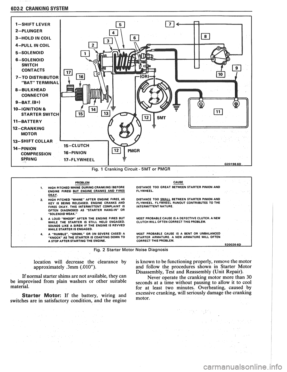
6D2-2 CRANKING SYSTEM
1-SWIFT LEVER m
SPRING 17-FLYWHEEL I
I G20198-6D
Fig. 1 Cranking Circuit - 5MT or PMGR
PROBLEM CAUSE - 1. HIGH PITCHED WHINE DURING CRANKING (BEFORE DISTANCE
TOO GREAT BETWEEN STARTER PINION AND
ENGINE FIRES) BUT ENGINE CRANKS AND FIRES FLYWHEEL.
OKAY - 2. HlGH PITCHED "WHINE"
AFTER ENGINE FIRES, AS
KEY IS BEING RELEASED. ENGINE CRANKS AND
FIRES OKAY. THlS INTERMITTENT COMPLAINT IS
OFTEN DIAGNOSED AS "STARTER HANG-IN"
OR "SOLENOID WEAK."
3. A LOUD "WHOOP" AFTER THE ENGINE FIRES BUT
WHILE THE STARTER IS STILL HELD ENGAGED.
SOUNDS
LIKE A SIREN IF THE ENGINE IS REVVED
WHILE STARTER IS ENGAGED.
4. A "RUMBLE. "GROWL" OR (IN SEVERE CASES) A
"KNOCK" AS THE STARTER IS COASTING DOWN TO
A STOP AFTER STARTING THE ENGINE. DISTANCE
TOO
SMALL BETWEEN STARTER PINION AND
FLYWHEEL. FLYWHEEL RUNOUT CONTRIBUTES TO THE
INTERMITTENT NATURE.
MOST PROBABLE CAUSE IS A DEFECTIVE CLUTCH. A NEW
CLUTCH
WlLL OFTEN CORRECT THlS PROBLEM.
MOST PROBABLE CAUSE IS A BENT OR UNBALANCED
STARTER ARMATURE. A NEW ARMATURE
WlLL OFTEN
CORRECT THlS PROBLEM.
620026.60
Fig. 2 Starter Motor Noise Diagnosis
location will decrease the clearance by is known to be functioning properly, remove the motor
approximately
.3mm (.01OU). and follow the procedures shown in Starter Motor
Disassembly, Test and Reassembly (Unit Repair).
If normal starter shims are not available, they can
Never operate the cranking motor more than 30
be improvised from plain washers or other suitable
seconds at a time without pausing to allow it to cool material.
for at least two minutes. Overheating, caused by
excessive cranking, will seriously
damage the cranking Starter Motor: If the battery, wiring and motor, switches are in satisfactory condition, and the engine
Page 460 of 1825
CRANKING SYSTEM BD2-9
I TESTING SERIES COIL FOR OPEN I
TESTING SOLENOID WINDINGS
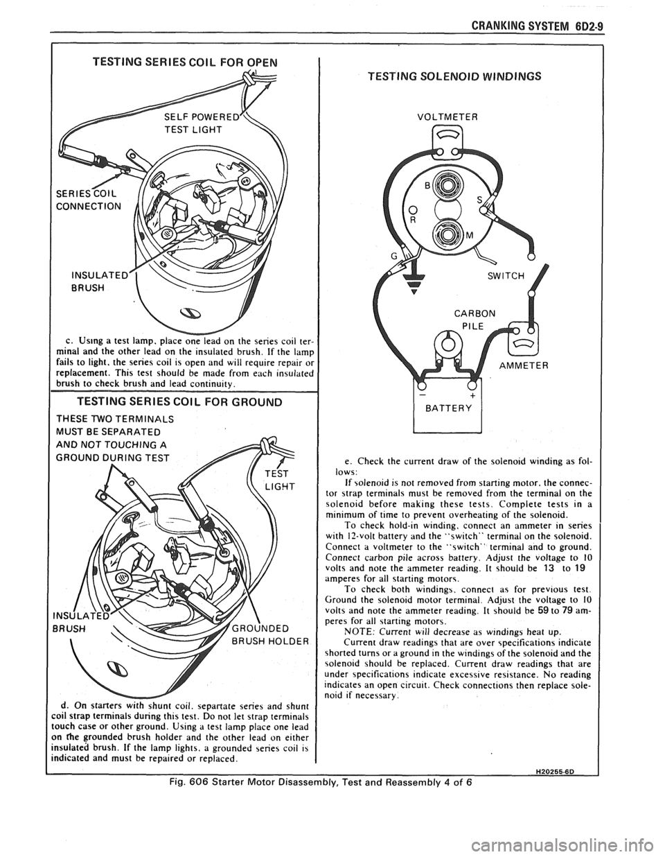
c. Us~ng a test lamp. place onelead on the series coil ter-
minal and the other lead on the insulated brush. If the lamp
fails to light. the series coil is open and will require repair or
replacement. This test should be made from each insulated
brush to check brush and lead continuity.
TESTING SERIES COlL FOR GROUND
THESE TWO TERMINALS
MUST BE SEPARATED
d. On starters
withshunt coil. sepanate series and shunt
coil strap terminals during this test. Do not let strap terminals
touch case or other ground. Using a test lamp place one lead
on
he grounded brush holder and the other lead on either
insulated brush. If the lamp lights, a grounded series coil is
indicated and must be repaired or replaced. VOLTMETER
e. Check the current draw of the solenoid winding as fol-
lows:
If solenoid is not removed from starting motor. the connec-
tor
strap terminals must be removed from the terminal on the
solenoid before making these tests. Complete tests in a
minimum of time to prevent overheating of the solenoid.
To check hold-in winding, connect an ammeter in series
with 12-volt battery and the "switch" terminal on the solenoid.
Connect a voltmeter to the "switch" terminal and to ground.
Connect carbon pile across battery. Adjust the voltage to
10 volts and note the ammeter reading. It should be 13 to 19 amperes for all starting motors.
To check both windings. connect as for previous test.
Ground the solenoid motor terminal. Adjust the voltage to 10
volts and note the ammeter reading. It should be
59 to 79 am-
peres for all starting motors.
NOTE: Current will decrease as windings heat up.
Current draw readings that are over specifications indicate
shorted turns or a ground in the windings of the solenoid and the
solenoid should be replaced. Current draw readings that are
under specifications indicate excessive resistance. No reading
indicates an open circuit. Check connections then replace sole-
noid if necessary.
H20255.6D
Fig. 606 Starter Motor Disassembly, Test and Reassembly 4 of 6
Page 472 of 1825
IGNITION SYSTEM 6B4-3
flash-over, which causes engine misfiring. Do not
mistake corona discharge for flash-over, or a shorted
insulator. Corona is a steady blue light appearing
around the insulator, just above the shell crimp. It is
the visible evidence of a high-tension field and has no
effect on ignition performance. Usually it can be
detected only in darkness. This discharge may repel
dust particles, leaving a clear ring on the insulator just
above the shell. This ring is sometimes mistakenly
regarded as evidence that combustion gases have blown
out between shell and insulator.
lgnition Switch
The mechanical switch is located in the steering
column on the right hand side just below the steering
wheel. The electrical switching portion of the assembly
is separate from the key and lock cylinder. However,
both are synchronized and work in conjunction with
each other through the action of the actuator rod
assembly.
For a complete explanation of the key and lock
cylinder, and the actuator rod assembly, see
STEERING, Section
38. See Section 8 for electrical
switching.
DIAGNOSIS
IGNITION SYSTEM
Spark Plugs
Worn or dirty plugs may give satisfactory
operation at idling speed, but at higher RPM they
frequently fail. Faulty plugs are indicated in a number
of ways: poor fuel economy, power loss, loss of speed,
hard starting and generally poor engine performance.
Spark plugs may also fail due to carbon fouling,
excessive gap, or a broken insulator. Fouled plugs may
be indicated by black carbon
deposits. The black deposits are usually the result of
slow-speed driving and short runs, where sufficient
engine operating temperature is seldom reached. Worn
pistons, rings, faulty ignition, over-rich carburetion
and spark plugs which are too cold will also result in
carbon deposits.
Excessive gap wear, on plugs of low mileage,
usually indicates the engine is operating at high speeds,
or loads that are consistently greater than normal, or
that a plug which is too hot is being used. Electrode
wear may also be the result of plug overheating,
causcd
by combustion gases leaking past the threads due to
insufficient torquing of the spark plug. Excessively lean
carburetion will also result in accelerated electrode
wear.
Broken insulators are usually the result of
improper installation, or carelessness when regapping
the plug. Broken upper insulators usually result from
a poor fitting wrench, or an outside blow. The cracked
insulator may not show up right away, but will as soon
as oil or moisture penetrates the crack. The crack is
usually just below the crimped part of shell and may
not be visible.
Broken lower insulators usually result from
carelessness when regapping and generally are visible.
This type of break may result from the plug operating
too "hot", which may happen in periods of high-speed
operation or under heavy loads. When regapping a
spark plug, always make the gap adjustment by
bending the ground (side) electrode. Spark plugs with
broken insulators should always be replaced.
HE1 Distributor
See Unit Repair for distributor disassembly, test
and reassembly of individual distributor components,
when the distributor is removed from the vehicle. See
On-Car Service for distributor removal and installation
and for component removal with distributor in car. See
Section 6E for
HE1 and EST diagnosis.
SERVICE PROCEDURES
IGNITION SYSTEM
Distributor Ignition
NOTICE: This procedure is generally true for
most carlines. Where procedure is different, or
where additional information is required, see
"ON-CAR SERVICE" for specific
carline.
HE1 DISTRIBUTOR
Service Precautions
1. When making compression checks, disconnect
the ignition switch feed wire at the distributor.
When disconnecting this connector,
do not use
a screwdriver or tool to release the locking tab, as
it may break.
2. No periodic lubrication is required. Engine oil
lubricates the lower bushing and an oil-filled
reservoir provides lubrication for the upper
bushing. 3.
The tachometer (TACH) terminal is next to the
ignition switch (BAT) connector on the
distributor cap.
NOTICE: The tachometer terminal must
NEVER be allowed to touch ground, as damage
to the module and/or ignition coil can result.
Some tachometers currently in use may NOT be
compatible with the High Energy Ignition System.
Consult the manufacturer of the tachometer if
questions arise.
4. Dwell adjustment is controlled by the module,
and cannot be adjusted.
5. The material used to construct the spark plug
cables is very soft. This cable will withstand more
heat and carry a higher voltage, but scuffing and
cutting become easier. The spark plug cables
must be routed correctly to prevent
chafing or
cutting. See Spark Plug Section. When removing