park assist PONTIAC FIERO 1988 Service Repair Manual
[x] Cancel search | Manufacturer: PONTIAC, Model Year: 1988, Model line: FIERO, Model: PONTIAC FIERO 1988Pages: 1825, PDF Size: 99.44 MB
Page 114 of 1825

CHASSIS SHEET METAL 2@-7
3. During the above flash time period (1 to 10 min-
utes), apply appropriate "conventional" interior acrylic lacquer color as required and allow
painted part to dry for
4 to 5 hours before install-
ing on car.
RlGlD OW HARD ABS PMS"TIC PARTS
Rigid or hard ABS plastic requires no primer.
"Conventional" interior acrylic lacquers adhere satis-
factorily to hard ABS plastics.
Procedure
1. Wash part thoroughly with a cleaning solvent
(Acrylic-Clean, Pre-Kleano, Prep-Sol or equiv-
alent) to remove any dirt or grease.
2. Apply appropriate "conventional" interior
acrylic lacquer color. Apply only sufficient
color for proper hiding to avoid washout of
"grain" effect.
3. Allow to dry and then install part.
VINYL AND FLEXIBLE (Son) ABS
PLASTIC PARTS
The outer cover or skin material of "flexible"
instrument panel cover (pad) assemblies is made of an
ABSIPVC plastic blend. The same is true of many
"padded" door trim assemblies. The soft cushion pad-
ding under the I.P. skin is urethane foam plastic. The
most widely used
"flexible" vinyls (poly vinyl chlo-
ride)
are coated fabrics, such as used in seat trim,
some door trim assemblies, molded headlining panels
and sun visors. Most head rests are "flexible" vinyls.
Examples of "hard vinyls are: door and front seat
back assist handles and coat hooks.
The paint system of vinyl and flexible ABS
plastic involves the use of interior "vinyl" color and a
clear vinyl top coat.
Procedure
1. Wash part thoroughly with a vinyl cleaning and
preparation solvent ("Vinyl Press"
- Ditzler,
"Vinyl Prep Conditioner"
- Detroit Autobody
or equivalent) to remove greasy film or silicone.
Wipe off cleaner while still wet with clean,
lint-
free cloth.
2. Immediately after wiping face dry, apply inte-
rior "vinyl" color in wet coats allowing suffi-
cient flash time between coats (see label
directions on can). Use proper "vinyl" color as
designated by interior trim combinations. Apply
only sufficient color for proper hiding to avoid
washout of "grain" effect. No primer or
primer-
sealer is required.
3. Before the final vinyl color coat has dried, apply
two coats of clear vinyl top coat spray (instru-
ment panels will require the "nonglare" clear top
coat). Do not allow the first spray coat to com-
pletely dry before spraying on the second. Use
top coat with appropriate gloss level to match adjacent similar components. This
clear coat is
necessary to control the gloss requirement and
prevent
'tracking" (rubbing-off) of the color
coat after drying.
4. Allow to dry according to label directions before
installing part.
ON-VEHICLE SERVICE
CONCEALED HEADLIGHTS
The concealed headlights used on this model are
electrically operated. When the headlights are turned
on, solid state circuitry activates the actuators. This
same circuitry senses when the actuators stop moving
and removes the ground to deactivate the actuators.
When the headlights are turned off, the actuators run
in opposite direction closing the headlight doors.
Should an electrical failure occur in the head-
light circuit, they may be raised manually by rotating
the knob on the actuator in a counterclockwise direc-
tion until the headlights are fully open. The headlights
may be lowered by rotating the knob on the actuator in
a clockwise direction until the headlights are fully
closed.
For electrical circuit information and diagnosis,
refer to Section
8A of this manual.
If it is desired to raise the headlights with the
lights off, either of the following procedures may be
used:
1. Turn the lights on. After the headlights are
open, disconnect the electrical connections at
the actuator connectors. Turn the lights off. The
headlights will now remain in the open position.
2. Turn the parking lights on. Depress the head-
light rocker switch lightly. The headlights may
then be raised "up" fully with the lights off.
Adjust
Because of the number of adjustments possible
and the number of attaching points of the concealed
headlight body assembly
(9), only those attachments
which control the adjustment desired should be loos-
ened. Make one
adjbstment at a time.
NOTICE: The headlight door does NOT have
slotted mounting holes and therefore is not
adjustable by itself. This insures proper clearance
between the headlight door and the hood and
fenders in both the raised and lowered positions.
The entire headlight body assembly must be
adjusted to achieve the desired appearance and
fit. Care should be exercised when adjusting the
headlight body assembly. Severe hammer blows could damage the die cast aluminum headlight
body assembly.
TO RAISE OR LOWER the headlight body
assembly, proceed as follows:
1. Open hood.
2. Raise headlights.
Page 128 of 1825

STEERING, SUSPENSION, VIBES AND WHEELS DIAGNOSIS 3-3
Steering Wheel Kick-Back (Power)
Inspect
e Air in system
e Loose steering gear mounting
e Joints from column to steering gear loose or worn
e Tie rod ends loose
Worn or missing check valve
(800 series)
e Wheel bearings worn
e See "Too Much Play In Steering" for other
possible causes.
Steering Wheel Surges Or Jerks (Power)
Inspect
Hydraulic system - Make pressure test with gage
J 5176-D or
J 25323
e Sluggish steering gear valve
Loose pump drive belt
Cupped Tires
Inspect
Front-wheel or rear-wheel alignment
e Strut dampeners or shock absorbers weak
e Wheel bearing worn
e Excessive tire or wheel runout
e Worn ball joint
a Loose steering gear adjustment
POWER RECIRCULATING BALL
SEERING GEAR DIAGNOSIS
Hissing Noise
There is some noise in all power steering systems.
One of the most common is a hissing sound when the
steering wheel is turned and the car is not moving. This
noise will be most evident when turning the wheel
while the brakes are applied. There is no relationship
between this noise and steering performance. Do not
replace the valve unless the "hissing" noise is extremely
objectionable. A replacement valve will also have a
slight noise, and is not always a cure for the condition.
Check that the intermediate shaft joints are not loose.
Rattle or Chucking Noise
Inspect -
Pressure hose grounding out
e Tie rod ends loose
e Steering gear attachment loose
a Loose pitman shaft "over-center" adjustment.
A slight rattle may occur on turns because of
increased clearance off the "high point". This is
normal and clearance must not be reduced below
specified limits to eliminate this slight rattle.
Poor Return of Steering Wheel to Center
Front-wheel alignment
Wheel bearing worn
Tie rod end binding
Ball joint binding
Steering wheel rubbing against turn signal
housing
Steering gear adjustments
Tight or frozen intermediate steering shaft
Sticky or plugged spool valve
Momentary Increase in Effort Whsn Turning
Wheel Fast to Right or Left
Inspect
High internal leakage
Steering Wheel Surges or Jerks When Turning
With
Engine Running Especially During Parking
ln8pe~t
e Insufficient pump pressure
Sticky flow control valve
Excessive Wheel Kickback or Loose Steering
Air in system
Steering gear attachment loose
Tie rod ends loose
Wheel bearings worn
Steering gear flexible coupling loose on shaft or
rubber disc mounting nuts loose
Loose thrust bearing preload adjustment
Excessive "over-center" lash
Worn pressure port check valve
Hard Steering or Lack of Assist
(Especially During Parking)
-
Brakes applied while turning steering wheel
Intermediate shaft damaged or worn
e Sticky flow control valve
Insufficient pump pressure
Excessive internal pump leakage
Excessive internal steering gear leakage
STEERING LINKAGE DIAGNOSIS
Excessive Play or Looseness in Steering Systern
inspect
r, Worn upper ball joints
e Steering gear worm bearings loosely adjusted
Page 329 of 1825

5C3-2 DIRECT TORQUE DRUM BRAKE ASSEMBLY
GENERAL DESCRIPTION
This drum brake asembly is a duo-servo, direct
torque design. In the duo-servo brake, the force which
the wheel cylinder applies to the primary shoe is
multiplied by the primary lining friction to provide a
very large force applied to the secondary shoe. With
the direct torque design, torque from the brake shoes
is transferred directly through the anchor pin to the
axle flange. Adjustment for both the primary and
secondary shoe and linings is automatic during reverse
brake applications.
Important
a Replace all components included in repair kits
used to service this drum brake.
a Lubricate parts as specified.
e Do not use lubricated shop air on brake parts as
damage to rubber components may result.
a If any hydraulic components is removed or
disconnected, it will be necessary to bleed all or
part of the brake system.
s Replace shoe and linings in axle sets only.
e The torque values specified are for dry,
unlubricated fasteners.
e Perform service operations on a clean bench free
from all mineral oil materials.
CAUTION: When servicing brake
parts, do not create dust by grinding or
sanding brake linings or by cleaning
wheel brake parts with a dry brush or
with compressed air.
A water
dampened cloth should be used.
Many
brake parts contain asbestos fibers
which can become airborne if dust is
created during servicing. Breathing
dust containing asbestos fibers may
cause serious bodily harm.
ON-CAR SERVICE
BRAKE COMPONENTS
Tool Required:
J 8049 Brake Spring Remover and Installer
J 8057 Brake Spring Pliers
J 29839 Brake Cylinder Retainer Remover
See Figures 2,3 and 4
Remove or Disconnect
1.
Raise car and suitably support, see Section OA.
e Mark relationship of wheel to axle flange.
2. Wheel and tire.
e Mark relationship of drum to axle flange.
3. Brake drum.
a If dificulty is encountered in removing
drum the following steps may be of
assistance:
@ Make sure parking brake is released.
a Back off parking brake cable
adjustment.
a Remove adjusting hole cover or
knockout plate from backing plate and
back off adjusting screw using screw
driver and adjusting tool.
a Use a rubber mallet to tap gently on
outer rim of the drum and/or around
inner drum diameter by spindle. Take
car not to deform by excessive use of
force.
4. Return springs (1 and 2) using
J 8049 pliers.
5. Hold-down springs (3) and pins (5) using suitable
pliers.
6. Lever pivot (4).
7. Actuator link (6) while lifting up on actuator
lever
(7).
8. Actuator lever (7) and lever return spring (8).
9.
Shoe guide (9), parking brake strut (10) and strut
spring
(1 1).
10. Shoe and lining assemblies (12 and 13) after
disconnecting parking brake cable.
11. Adjusting screw assembly (29) and spring (14).
12. Parking brake lever (18) by unhooking lever tab
from secondary shoe (13) slot.
e If any parts are of doubtful strength or quality
due to discoloration from heat, over-stress, or are
worn, the parts should be replaced.
Page 1117 of 1825

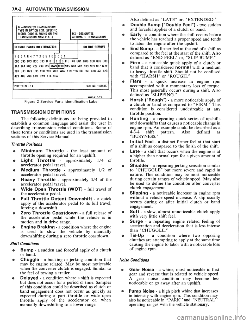
7A-2 AUTOMATIC TRANSMISSION
I I
M - INDICATES TRANSMISSION
TYPE IN OPTION LIST. (SPECIFIC MODEL CODE IS FOUND ON THE I MX - DESIGNATES
11 SERVICE PARTS IDEMTIFICATIOM I 1 00 MOT REMOVE I
1G3AR47YXE5
C90 C95 DF3 D3C 033 0 GI GW9 G60 GU2 G89
JAl JA4 KO5 K22 Kg9 LV2 NA5 NB1 NKl NK3 N33 N67 GJW
T87 UJ3 U23 U35
VO8 V10 WC3 WG2 YT9 Y56 OIL 6SC 428 421 420
Figure 2 Service Parts ldentificaiton Label
TRANSMISSION DEFINITIONS
The following definitions are being provided to
establish a common language and assist the user in
describing transmission related conditions. Some of
these terms or conditions are used in the transmission
sections of this Service Manual.
Throttle Positions
Minimum Throttle - the least amount of
throttle opening required for an upshift.
Light Throttle - approximately 1/4 of
accelerator pedal travel.
Medium Throttle - approximately 1/2 of
accelerator pedal travel.
Heavy Throttle - approximately 3/4 of the
accelerator pedal travel.
Wide Open Throttle (WOT) - full travel of
the accelerator pedal.
Full Throttle Detent Downshift - a quick
apply of the accelerator pedal to its full travel,
forcing a downshift.
Zero Throttle Coastdown - a full release of
the accelerator pedal while the vehicle is in
motion and in drive range.
Engine Braking - a condition where the engine
is used to slow the vehicle by manually
downshifting during a zero throttle coastdown.
Shift Conditions
'a Bump - a sudden and forceful apply of a clutch
or band.
Q Chuggle - a bucking or jerking condition that
may be engine related. May be most noticeable
when the converter clutch is engaged. Similar to
the feel of towing a trailer.
e Delayed - a condition where a shift is expected
but does not occur for a period of time. Samples
of this condition could be described as clutch or
band engagement does not occur as quickly as
expected during a part throttle or wide open
throttle apply of the accelerator or, when
manually downshifting to a lower range. Also
defined as "LATE" or, "EXTENDED."
Double Bump ("Double Feel") - two sudden
and forceful applies of a clutch or band.
Early - a condition where the shift occurs before
the vehicle has reached a proper speed and tends
to labor the engine after the upshift.
End Bump - a firmer feel at the end of a shift as
compared to the feel at the start of the shift. Also
defined as "END FEEL" or, "SLIP BUMP."
Firm - a noticeable quick apply of a clutch or
band that is considered
normal with a medium
to heavy throttle shift. Should not be confused
with "HARSH" or "ROUGH."
Flare - a quick increase in engine rpm
accompanied with a momentary loss of torque.
This most generally occurs during a shift. Also
defined as "SLIPPING.
"
Harsh ("Rough") - a more noticeable apply of
a clutch or band as compared to "FIRM." This
condition is considered undesireable at any
throttle position.
Hunting - a repeating quick series of upshifts
and downshifts that causes a noticeable change in
engine rpm. An example could be described as a
4-3-4 shift pattern. Also defined as
"BUSYNESS.
"
Initial Feel - a distinct firmer feel at that start
of a shift as compared to the finish of the shift.
Late - a shift that occurs when the engine is at
a higher than normal rpm for a given amount of
throttle.
Shudder - a repeating jerking sensation similar
to "CHUGGLE" but more severe and rapid in
nature. This condition may be most noticeable
during certain ranges of vehicle speed. May also
be used to define the condition after converter
clutch engagement.
Slipping - a noticeable increase in engine rpm
without a vehicle speed increase.
A slip usually
occurs during or after initial clutch or band
engagement.
Soft - a slow, almost unnoticeable clutch apply
with very little shift feel.
Surge - a repeating engine related feeling of
acceleration and deceleration that is less intense
than "CHUGGLE.
"
Tie-Up - a condition where two opposing
clutches are attempting to apply at the same time
causing the engine to labor with a noticeable loss
of engine rpm.
,e Conditions
Gear Noise - a whine, most noticeable in first
gear and reverse that is related to vehicle speed.
A gear noise condition may become less
noticeable or go away after an upshift.
Pump Noise - a high pitch whine that increases
in intensity with engine
rpm. This condition may
also be noticeable in
"PARK" and "NEUTRAL"
operating ranges with the vehicle stationary.