power steering fluid PONTIAC FIERO 1988 Service Repair Manual
[x] Cancel search | Manufacturer: PONTIAC, Model Year: 1988, Model line: FIERO, Model: PONTIAC FIERO 1988Pages: 1825, PDF Size: 99.44 MB
Page 21 of 1825
OB-4 MAINTENANCE AND LUBRICATION
Tire and wheel operation - Be alert to a vibra-
tion of the steering wheel or seat at normal highway
speeds. This may mean a wheel balance is needed. Also, a
pull right or left on a straight, level road may show the
need for
a tire pressure adjustment or wheel alignment.
Steering system operation - Be alert to
changes in steering action. An inspection is needed when
the steering wheel is harder to turn or has too much free
play or if unusual sounds are noted when turning or
parking.
Headlight aim operation - Take note of light
pattern occasionally. If beam aim doesn't look right,
headlights should be adjusted.
AT EACH FUEL FILL
Engine oil level check - Check engine oil level
and add if necessary. See your Owner's
Manual for further
details.
NOTICE: A large loss in this system may indicate a
problem. Have it inspected and repaired at once.
Engine coolant level and condition - Check
engine coolant level in coolant reservoir tank and add if
necessary. Replace if dirty or rusty. See your Owner's
Manual for further details.
NOTICE: A large loss in this system may indicate a
problem. Have it inspected and repaired at once.
Windshield washer fluid level check -- Check
washer fluid level in container and add if necessary.
Hood latch operation - When opening hood on
cars equipped with hoods that open from the front, note
the operation of secondary latch. It should keep hood from
opening all the way when primary latch is released. Make
sure that hood closes firmly.
AT LEAST MONTI-ILY
Tire and wheel inspection and pressure
check--
Check tires for abnormal wear or damage. Also,
check for damaged wheels. Keep pressures as shown on
Tire Placard on the driver's door (include spare unless it is
a stowaway). Pressure should b\: checked when tires are
"cold". See "Tires" in Owner's Manual for further
infomation.
Light operation check - Check operation of
license plate light, side-marker lights, headlights includ-
ing high beams, parking lights, taillights, brake lights.
turn signals, backup lights, instrument panel and interior
lights and hazard warning flashers.
Fluid leak check - After the car has been parked
for a while, inspect the surface beneath the car for water,
oil, fuel or other fluids. Water dripping from the air
conditioning system after use is normal. If you notice fuel
leaks or fumes, the cause should be found and corrected at
once.
AT LEAST TWICE A YEAR (FOR EXAMPLE,
EVERY SPRING AND FALL)
Power steering pump fluid level check --
Check power steering pump fluid level in accordance with
Owner's Manual instructions and keep at proper level.
NOTICE: A large loss in this system may indicate a
problem. Have it inspected and repaired at once.
Brake master cylinder reservoir fluid level
check ---- Check fluid and keep at proper level. Note: It is
normal for the brake fluid level to go down slightly as the
brake pads wear
- so be sure to keep reservoir filled.
NOTICE: A large loss in this system may indicate a
problem. Have
it inspected and repaired at once.
Clutch system service --- manual transmis-
sionltransaxle --- For cars equipped with hydraulic
clutch system, check the reservoir fluid level and add fluid
as required. All others, check clutch pedal free travel and
adjust as necessary. See your Owner's Manual for further
details.
~
NOTICE: A large loss in this system may indicate a
problem. Have it inspected and repaired at once.
Weatherstrip Lubrication - Clean surface and
then apply a thin film of silicone grease with a clean cloth.
EACH TIME OIL IS CHANGED
Automatic and manual transmissionltrans-
axle fluid level check - Check transmission/transaxle
fluid level and add as required. (Corvette only) if equipped
with manual transmission
- check fluid in the overdrive
unit and add as required.
NOTICE: A large loss in this system may indicate a
problem. Have
it inspected and repaired at once.
Brake systems inspection - For convenience,
the following should be done when wheels are removed
for rotation: Inspect lines and hoses for proper hookup,
binding, leaks, cracks, chafing, etc. Inspect disc brake
pads for wear and rotors for surface condition. Also in-
spect drum brake linings for wear and cracks. Inspect
other brake parts, including drums, wheel cylinders, park-
ing brake, etc. at the same time. Check parking brake
adjustment.
INSPECT BRAKES MORE OFTEN IF DRIVING
HABITS OR CONDITIONS RESULT IN FREQUENT
BRAKING.
Steering, suspension and front drive axle
boot and seal inspection
- Inspect front and rear
suspension and steering system for damaged, loose or
missing parts, signs of wear or lack of lubrication. Inspect
power steering lines and hoses for proper hookup, bind-
ing, leaks, cracks, chafing, etc. (On cars equipped with
manual steering gear, check for seal leakage.) On
front-
wheel-drive cars, clean then inspect drive axle boot seals
for damage, tears or leakage. Replace seals if necessary.
Exhaust system inspection - Inspect complete
system. Inspect body near the exhaust system. Look for
broken, damaged, missing or out-of-position parts as well
as open seams, holes, loose connections or other condi-
tions which could cause a heat buildup in the tloor pan or
could let exhaust fumes seep into the trunk or passenger
compartment.
Page 22 of 1825
MAINTENANCE AND LUBRICATION OB-5
Throttle linkage inspection -- Inspect for inter-
ference, binding, damaged or missing parts.
Engine drive belts inspection - Inspect all
belts for cracks, fraying and wear. Adjust or replace as
needed.
Rear axle service (if equipped) - Check gear
lubricant level and add if needed. For cars equipped with a
limited slip rear axle, fluid does not require changing
(except Caprice and Corvette
- change fluid and required
additive at first
7,500 miles (12 500 km). See your
Owner's Manual or "Recommended Fluids
& Lubricants
Chart" in this section.
IF YOU USE YOUR GAR TO PULL A TRAILER,
CHANGE GEAR LUBRICANT EVERY 7,500 MILES
(12 500 KM).
NOTICE: A large loss in this system may indicate a
problem. Have it inspected and repaired at once.
Power antenna - Clean and then lubricate power
antenna mast. The proper lubricant as shown in Figure
OB-2 should be used.
AT LEAST ONCE A YEAR
Lap and shoulder belts condition and opera-
tion
- Inspect belt system, including webbing, buckles,
latch plates, retractors, guide loops and anchors.
Moveable head restraint operation - On cars
with moveable restraints, make sure restraints stay in the
desired position. (See adjustment instructions in your
Owner's Manual.)
Seatback latch and recliner operation on
cars equipped
with recliner seat --- Be sure seat-
backs latch on those cars with folding seats using mechan-
ical latches. Make sure the recliner is holding by pushing
and pulling on the top of the
seatback while it is reclined.
See your Owner's Manual for seat operating information.
Spare tire and jack storage- Be alert to rattles
in rear of car. Make sure the space tire, all jacking equip-
ment, any tire inflator and any covers or doors are securely
stowed at all times. Oil jack ratchet or screw mechanism
after each use.
Key lock service - Lubricate key lock cylinder at
least annually.
Body lubrication service - Lubricate all body
door hinges including the tailgate or hatchback lid (if
equipped). Also lubricate the body hood, fuel door and
rear compartment hinges and latches including interior
glove box and counsel doors, and any folding seat
hardware.
"Fansmissionltransaxle neutral or clutch
starl switch operation
CAUnON: Before pedorming the follow-
ing safety switch check, be sure to have
enough room around the car. Then, firmly
apply both the parking brake (see your
Owner's Manual for procedure) and the
regular brakes. Do not use the accelerator pedal.
If the engine
starls, be ready to turn
off the ignition promptly. Take these pre-
cautions because the car could move
without warning and possibly cause per-
sonal injury or properly damage. On auto-
matic transmissionltransaxle cars, try to
starl the engine in each gear. The starler
should crank only in "Park" or "Neutral."
On manual transmissionltransaxle cars,
place the
shiR lever in "Neutral," push the
clutch halfway and try to starl. The starler
should crank only when the clutch is fully
depressed.
Steering column lock operation
- While
parked, try to turn key to "Lock" in each gear range. The
key should turn to "Lock" only when gear is in "Park" on
automatic or "Reverse" on manual
transmissionltransax-
le. On cars with key release lever, try to turn key toULock"
without depressing the lever. The key should turn to
"Lock" only with the key lever depressed. On all vehicles,
the key should come out only in "Lock."
Parking brake and transmissionltransaxle
"Park" mechanism operation
CAUT1ON:Before checking the holding
ability of the parking brake and automatic
transmissionltransaxle "Park" mecha-
nism, park on a fairly steep hill with
enough room for movement in the down-
hill direction. To reduce the risk of person-
al injury or property damage, be prepared
to apply the regular brakes promptly if the
car begins to move.
To check the parking brake, with the engine running and
transmission/transaxle in "Neutral." slowly remove foot
pressure from the regular brake pedal (until the car is held
by only the parking brake).
To check the automatic transmissionltransaxle "Park"
mechanism holding ability, release all brakes after shift-
ing the transmissionltransaxle to "Park."
ljnderbody flushing - At least every spring,
tlush from the underbody with plain water any corrosive
materials used for ice and snow removal and dust control.
Take care to thoroughly clean any areas where mud and
other debris can collect.
Sediment packed in closed areas
of the vehicle should be loosened before being flushed.
Engine cooling system service - Inspect
coolant and freeze protection. If dirty or rusty, drain, flush
and refill with new coolant. Keep coolant
at the proper
mixture as specified in your Owner's Manual. This pro-
vides proper freeze protection. corrosion inhibitor level
and engine operating temperature. Inspect hoses and re-
place if cracked. swollen or deteriorated. Tighten hose
clamps. Clean outside of radiator and air conditioning
condensor. Wash radiator filler cap and neck.
To help
ensure proper operation. a pressure test of both the cooling
system and cap is also recommended. (See maintenance
schedule charts in Figure
OB-l for the recommended
coolant change interval.)
Page 23 of 1825
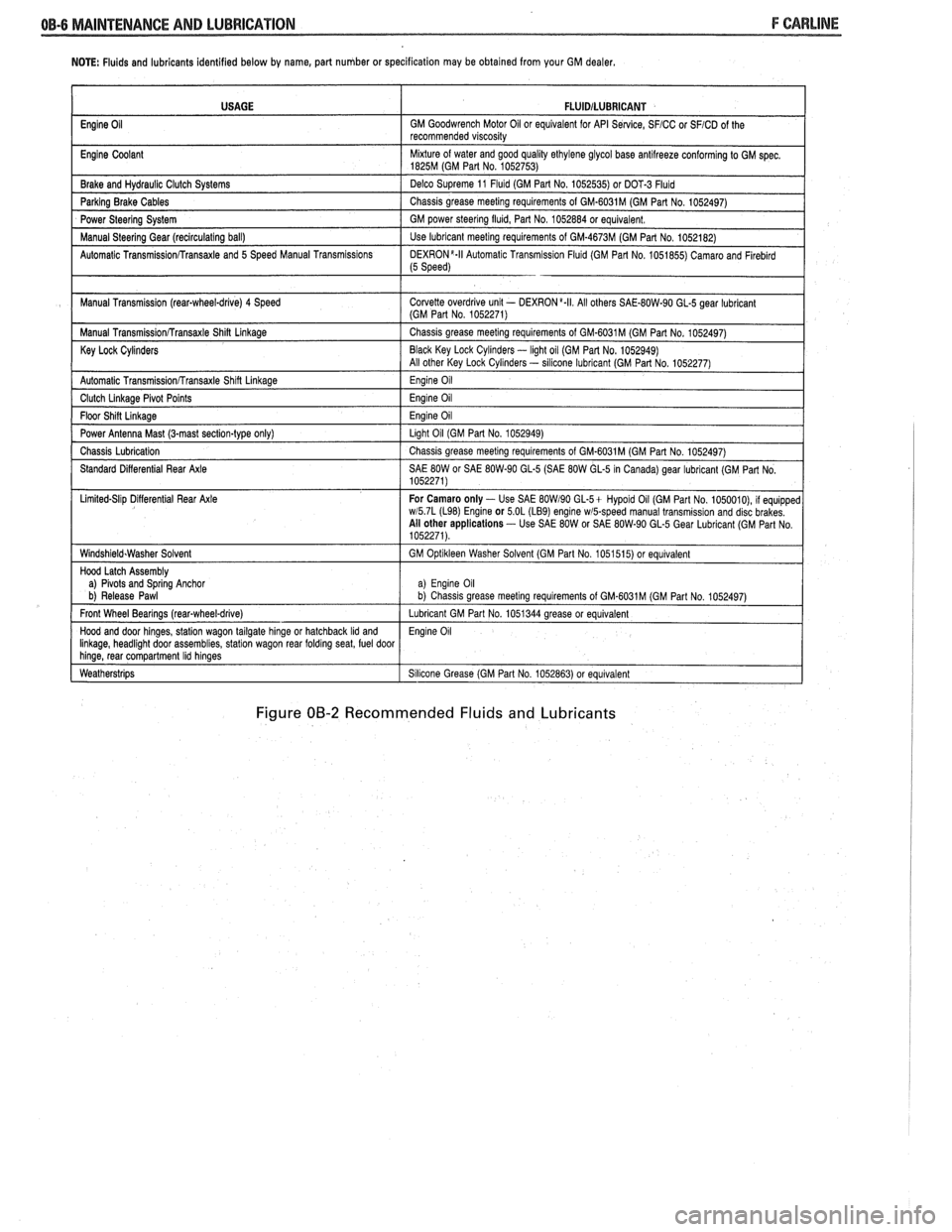
NOTE: Fluids and lubricants identified below by name, part number or specification may be obtained from your GM dealer.
Figure 00-2 Recommended Fluids and Lubricants
USAGE
Engine
Oil
Engine Coolant
Brake and
Hydraul~c Clutch Systems
Parking Brake Cables
Power Steering System
Manual
Steerlng Gear (reclrculat~ng ball)
Automatic
Transrn~ssionRransaxle and 5 Speed Manual Transm~ss~ons
Manual Transm~ssion (rear-wheel-drive) 4 Speed
Manual
Transm~ss~onRransaxle Shin Linkage
Key Lock Cylinders
Automatic Transmlss~onfrransaxle Shlft Llnkage
Clutch Llnkage Plvot Po~nts
Floor Sh~n L~nkage
Power Antenna Mast (3-mast sect~on-type only)
Chass~s Lubr~cation
Standard D~fferent~al Rear Axle
L~m~ted-Sl~p D~flerent~al Rear Axle
W~ndsh~eld.Washer Solvent
Hood Latch Assembly
a)
Plvots and Sprlng Anchor
b) Release Pawl
Front Wheel Bearings
(rearqwheel-drive)
Hood and door hlnges, statlon wagon tailgate hlnge or hatchback Ild and Ilnkage, headl~ght door assembl~es, statlon wagon rear foldrng seat, fuel door hlnge, rear compartment Ihd hlnges
Weatherstr~ps
FLUlDlLUBRlCANT
GM Goodwrench Motor 011 or equivalent for API Se~lce, SFICC or SFICD of the
recommended v~scos~ty
M~xture of water and good qual~ty ethylene glycol base antllreeze conforming to GM spec 1825M (GM Part No 1052753)
Delco Supreme 11
Fluld (GM Part No 1052535) or DOT-3 Fluld
Chass~s grease meetlng requirements of GM-6031M (GM Part No 1052497)
GM power
steerlng flu~d, Part No 1052884 or equivalent
Use lubricant meetlng requirements of GM-4673M (GM Part No 1052182)
DEXR0N'-II Automat~c Transm~ss~on Flu~d (GM Part No 1051855) Camaro and Flreblrd (5 Speed)
Corvette overdr~ve unlt - DEXRON a.II All others SAE-80W-90 GL-5 gear lubr~cant (GM Part No 1052271)
Chass~s grease meetlng requirements of GM-6031M (GM Part No 1052497)
Black Key Lock
Cyl~nders - light oil (GM Par1 No. 1052949)
All other Key Lock Cyl~nders - sllicone lubrlcant (GM Part No 1052277)
Eng~ne 011
Eng~ne 011
Eng~ne 011
Llght 011 (GM Part No 1052949)
Chass~s grease meetlng requirements of GM-6031M (GM Part No 1052497)
SAE
80W or SAE 80W-90 GL-5 (SAE 80W GL-5 In Canada) gear lubricant (GM Part No
1052271)
For Camaro only
- Use SAE BOW190 GL-5+ Hypold 011 (GM Part No 1050010), 11 equ~pped wl5 7L (L98) Englne or 5 OL (LB9) engine wmpeed manual transm~ss~on and disc brakes
All other applications - Use SAE 80W or SAE 80W-90 GL-5 Gear Lubr~cant (GM Part No
1052271)
GM
Opt~kleen Washer Solvent (GM Part No 1051515) or equ~valent
a) Eng~ne 011 b) Chass~s grease meet~ng requirements of GM.6031M (GM Part No 1052497)
Lubricant GM Part No 1051344 grease or equivalent
Eng~ne 011
S~l~cone Grease (GM Part No 1052863) or equivalent
Page 126 of 1825
STEERING, SUSPENSION, f IRES AND WHEELS DIAGNOSIS 3.1
SECVION 3
STEER NG, SUSPENS
WHEELS
AGNOS
CONTENTS
........................................... General Information 3- 1 ............................................ General Diagnosis 3- 1
Power Recirculating Ball .................................. 3-3
................. Steering Linkage ........................ .. 3-3
Power Steering Pump ................... ... ............ 3-4
Steering Column
Lock System
........................... ... ................ 3-4
Column ............................................................ 3-5
........................................ Turn Signal Switch 3-6
Ignition Switch .............................................. 3-7
Key Reminder .............................................. 3-7
Dimmer Switch .................... ... ................ 3-10
Pivot and Switch Assembly ............................ 3-10
Steering Gear and Pump Leaks .......................... 3- 10
Seal Replacement Recommendations ................. 3- 10
Power Steering System Test Procedure .............. 3-12
................ Strut Dampener and Shock Absorber 3- 12
Tires ........................ .. ..................................... 3- 13
Vibrations .......................... .............. .................... 3- 14
.......................... Tapered Roller Bearings .. .... 3- 14
Trim Height .............................................. 3-14
GENERAL INFORMATION Abnormal or Excessive Tire Wear
Since the problems in steering, suspension, tires
and wheels involve several systems, they must all be
considered when diagnosing a complaint. To avoid
e Front-wheel or rear-wheel alignment
using the wrong symptom, always road test the car
o Sagging or broken springs
first. Proceed with the following preliminary checks
Tire out of balance and correct any substandard conditions which are worn strut dampener or shock absorber found. o Hard driving
--
e Tires for wrong pressure and uneven wear
o Joints from the column to the steering gear for
loose connectors or wear
o Front and rear suspension, and the steering gear
or linkage for loose or damaged parts
Out-of-round or out-of-balance tires, bent wheels,
and loose and/or rough wheel bearings
@ Power steering system for leaks. Also check the
power steering fluid level and the pump drive belt
tension
GENERAL DIAGNOSIS
Car Pulls (Leads)
Inspect
Mismatched or uneven tires
Broken or sagging springs
Radial tire lateral force
Front-wheel or rear-wheel alignment
o Steering gear valve off center (unbalanced)
e Front brakes dragging
a Overloaded car
e Not rotating tires
Scuffed Tires
o Toe incorrect
e Excessive speed on turns
o Suspension arm bent or twisted
Wheel Tramp
Inspect
o Blister or bump on tire
o Improper strut dampener or shock absorber
action
Shimmy, Shake or Vibration
inspect
e Tire or wheel out of balance
e Worn wheel bearings
a Worn tie rod ends
o Worn lower ball joints
Page 129 of 1825
3.4 STEERING, SUSPENSION, TIRES AND WHEELS DIAGNOSIS
e Excessive pitman shaft to ball nut lash in steering
gear
e Worn intermediate rod or tie rod sockets
Excessive Looseness in Tie Rod or Intermediate
Rod Pivots, or Excessive Vertical Lash in
Idler
Support
Inspect -
e Seal damage and leakage resulting in loss of
lubricant, corrosion and excessive wear
Hard Steering
0 Inspect
e Tight or frozen intermediate rod, tie rod or idler
socket
e Steering gear adjusted too tight
POWER STEERING PUMP DIAGNOSIS
Foarning, Milky Power Steering Fluid, Low Fluid
Level, and Possible Low Pressure
This can be caused by air in the fluid, and loss of
fluid due to internal pump leakage causing overflow.
Check for leak and correct. Bleed the system.
Extremely cold temperatures will cause air bubbles in
the system if the fluid level is low. If the fluid level is
correct and pump still foams, remove pump from car
and separate reservoir from housing. Check soft plug
and housing for cracks. If housing is cracked, replace
housing.
Low Pressure Due to Steering Pump
Inspect
e Flow control valve stuck or inoperative
e Pressure plate not flat against cam ring
e Extreme wear of cam ring
e Scored pressure plate, thrust plate or rotor
e Vanes sticking in rotor slots
Q Cracked or broken thrust or pressure plate
e High internal leakage
Low Pressure Due To Steering Gear
Inspect
e Scored housing bore
Q Leakage at valve rings or seals
Growling Noise in Steering Pump
Inspect
e Excessive back pressure in hoses or steering gear
caused by restriction
e Scored pressure plates, thrust plate or rotor
e Worn cam ring
Groaning Noise in Steering Pump
Inspect
e Air in the fluid
Low fluid level
Q Pump mounting loose
Rattling Noise in Steering Pump
Inspect - -
e Vanes sticking in rotor slots
o Vane improperly installed
o Damaged ball bearing
Swishing Noise in Steering Pump
inspect
e Damaged flow control valve
Whining Noise in Steering Pump
Inspect
Q Pump shaft bearing scored
e Scored pressure plates and vanes
STEERING COLUMN DIAGNOSIS
LOCK SYSTEM
Will Not Unlock
Inspect
o Shear flange on sector shaft collapsed
Q Damaged lock bolt
e Damaged lock cylinder
o Damaged housing
e Damaged sector
e Damaged rack
e Damaged park lock cable
Will Not Lock
Inspect
Lock bolt spring broken or worn
Damaged sector
Damaged lock cylinder
Burr on lock bolt
Damaged housing
Improper shift linkage adjustment
Damaged rack
Interference between bowl and rack coupling
Ignition switch stuck
Actuator rod restricted
Sector installed incorrectly
Park lock cable damaged
Page 135 of 1825
3-10 STEERING, SUSPENSION, TIRES AND WHEELS DIAGNOSIS
Reminder Keeps Operating With Key In Lock
Cylinder, Driver's Door Open Or Closed; Ceases
When Key Is Removed
Inspect
s Door jamb switch on driver's side misadjusted or
inoperative.
e Wire from signal switch to door jamb switch
shorted.
A. This condition indicates the lock cylinder or
the reminder switch is at fault. To verify,
check for continuity at the
"E" and "F"
male column connector contacts, with the
key removed from the lock cylinder. If
continuity exists, the fault is in the column.
B. Insert the key into the lock, then turn the
lock toward the "Start" position. If the
reminder stops when the key is in the
"Run" position or when it is turned past
"Run" toward "Start," the problem is a
sticky lock cylinder actuator.
COLUMN-MOUNTED DIMMER SWITCH
No "Low" or "High" Beam
Inspect
e Loose connector at dimmer switch
e Improper adjustment
e Internally damaged or worn switch. Check the
continuity on the switch at the It. green and at the
tan switch terminals by pushing in the plunger all
the way.
A click should be heard. If there is no
continuity, replace the dimmer switch. If there is
continuity, refer
to'section 8A for electricaldiag-
nosis.
PIVOT AND SWITCH ASSEMBLY
Switch Inoperative: No "Low," "High" and/or
"Wash"
e Loose body-to-switch connector
a Broken or damaged switch
Internally damaged or worn switch. Connect a
new switch without removing the old one. If the
system functions, replace the switch. If the
system doesn't function, refer to Section
8A for
electrical diagnosis.
STEERING GEAR AND PUMP LEAKS
General Procedure
Inspect
s Overfilled reservoir
s Fluid aeration and overflow
e , Hose connections
Verify exact point of leakage Example:
Torsion bar, stub shaft and
adjuster seals are close together; the exact
spot where the system is leaking may not be
clear.
Example: The point from which the fluid is
dripping is not necessarily the point where
the system is leaking; fluid overflowing from
the reservoir, for instance.
e When service is required:
A. Clean leakage area upon disassembly.
B. Replace leaking seal.
C. Check component sealing surfaces for
damage.
D. Reset bolt torque to specifications, where
required.
Some complaints about the power steering system
may be reported as:
A. Fluid leakage on garage floor
B. Fluid leaks visible on steering gear or pump
C. Growling noise, especially when parking or
when engine is cold
D. Loss of power steering when parking
E. Heavy steering effort
When troubleshooting these kinds of complaints,
check for an external leak in the power steering system.
For further diagnosis of leaks, refer to External
Leakage Check in this section.
External Leakage Check
Fig. 12
The purpose of this procedure is to pinpoint the
location of the leak.
In some cases, the leak can easily be located. But,
seepage-type leaks may be more difficult to isolate. To
locate seepage leaks, use the following method.
1. With the engine off, wipe dry the complete power
steering system.
2. Check the fluid level in the pump's reservoir. Add
fluid if necessary.
3. Start the engine, then turn the steering wheel
from stop to stop several times. Do not hold it at
a stop for any length of time, as this can damage
the power steering pump. It is easier if someone
else operates the steering wheel while you search
for the seepage.
4. Find the exact area of the leak and repair leak.
SEAL REPLACEMENT
RECOMMENDATIONS
Lip seals, which seal rotating shafts, require
special treatment. This type of seal is used on the
steering gear and on the drive shaft of the pump. When
there is a leak in one of these areas, always replace the
seal(s), after inspecting and thoroughly cleaning the
sealing surfaces. Replace the shaft only if very severe
pitting is found. If the corrosion in the lip seal contact
zone is slight, clean the surface of the shaft with crocus
cloth. Replace the shaft only if the leakage cannot be
stopped by first smoothing with crocus cloth.
Page 137 of 1825

3-1 2 STEERING, SUSPENSION, TIRES AND WHEELS DIAGNOSIS
POWER STEERlNG SYSTEM "TEST
PROCEDURE
Fig. 13 1. J-5176-D 2. LlNE TO STEERING GEAR
1. Disconnect pressure hose at pump. Use a small 3. LINE TO POWER STEERING PUMP
container to catch any fluid which might leak.
2. Connect a spare pressure hose to pump.
3. Connect pressure gage
J 5176-D
to both hoses.
e The power steering system may be tested
using
J 5 176-D as described here. It can also
be tested with available tool
J 25323 Power
Steering Analyzer, which will measure flow
rate as well as pressure.
4. Open valve on gage.
5. Start the engine. Allow the system to reach
operating temperature, then check the fluid level
and add fluid if required.
6. When the engine is at normal operating
temperature, the pressure reading on the gage
(valve open) should be in the 552-862
kPa (80-125
psi) range. If the pressure is more than 1 380
kPa
(200 psi), check the hoses for restrictions and the
poppet valve on the steering gear for proper
assembly.
7. Fully close the valve 3 times. (Do not leave the
valve fully closed for more than 5 seconds, as the
pump could be damaged.) Record the pressure
reading each time the valve is closed. Each
reading should show at least 6 895
kPa (1,000
psi), or at least 8 619 kPa (1,250 psi) on the TC
series pumps. The three readings should be within
345
kPa (50 psi) of each other.
A. If the pressure readings are high enough,
and are within 345
kPa (50 psi) of each
other, the pump is functioning properly.
B. If the pressure readings are high enough,
but are not within 345
kPa (50 psi) of each
other, the flow control valve in the pump is
sticking. Remove the valve; clean it and
remove any burrs using crocus cloth or fine
hone. If the system contains some dirt, flush
it. If it is exceptionally dirty, both the pump
and the steering gear must be completely
disassembled, cleaned and reassembled.
C. If the pressure readings are less than
6 895
kPa (1,000 psi), or are less than 8 619 kPa
(1,250 psi) on the TC series pumps, replace
the flow control valve and recheck. If the
pressures are still low, replace the rotor and
vanes.
8. If the pump checks to specification, leave the
valve open and turn (or have turned) the steering
wheel to both stops. Record the highest pressures
and compare with the highest pump pressure
recorded. If the pressure at both stops is not the
same as the maximum pressure, the steering gear
is leaking internally and must be disassembled
and repaired.
9. Turn off the engine, then remove the testing gage
and the spare hose. Reconnect the pressure hose,
check the fluid level or make needed repairs.
Fig. 13 Power Steering Pressure Gage
STRUT DAMPENER AND SHOCK
ABSORBER DIAGNOSIS
The strut dampener is basically a shock absorber.
Strut dampeners are easier to extend and retract by
hand than are shock absorbers.
The following procedure includes both on-car
and bench checks to be done when evaluating the
performance of strut dampeners and shock absorbers.
ON-CAR CHECKS
Weak
For struts, follow Steps 1 through 4.
1. Check
and adjust tire pressures to the pressures
shown on the Tire Placard.
2. Note the load conditions under which the car is
normally driven.
3. If practical, ride with the owner to be sure you
understand the complaint before proceeding to
next step.
4. Test each strut
dampener/shock in turn by
quickly pushing down, then lifting up, the corner
of the bumper nearest the strut
dampener/shock
being checked. Use the same amount of effort on
each test and note the resistance on compression
and rebound. Compare this with a similar car
having acceptable ride quality. Both strut
dampeners/shocks should provide the same
feeling of resistance.
If there is much difference between the right and
left rear shocks, go to the next step.
5. Support the rear axle at least enough to unload
the shock mounts.
6. Disconnect the lower shock mountings. Stroke
the shocks at various rates of speed, through
maximum travel in both directions. Compare the
two sides for rebound and compression
resistance. Rebound resistance is normally
stronger than compression (about 2 to 1). The
right and left shocks must feel comparable.
Differences between front and rear are normal. If
Page 194 of 1825
POWER Sf EERING 387-1
SECTION 3B7
POWER STEER NG GEAR AND PUMP
The following notice applies to one or more steps in the assembly procedure of components in this portion
of the manual as indicated at appropriate locations. "See Notice on Page
1 of this Section".
NOTICE: Steering column fasteners are important attaching parts in that they may affect the performance
of vital components and systems, and/or could result in major repair expense. They must be replaced with one
of the same part number or with an equivalent part if replacement becomes necessary. Do not use a replacement
part of lesser quality or substitute design. Torque values must be used as specified during reassembly to assure
proper retention of these parts. For prevailing torque
nut(s) and bolt(s), refer to the "Reuse of Prevailing Torque
Nut(s) and Bolt(s)" chart in Section 10.
CONTENTS
MAINTENANCE AND ADJUSTMENTS
Bleeding Hydraulic System
................................................................................................. 3B7- 1
Fluid Level ......................................................................................................................... 3B7- 1
Power Steering Gear Adj. ..................................................................................................... 3B7- 1
Drive Belt Tension .............................................................................................................. 3B7-2
Hydraulic System Checks .................................................................................................. 3B7-2
Hydraulic System Test ......................................................................................................... 3B7-2
ON-VEHICLE SERVICE
Steering Gear Removal
...................................................................................................... 3B7-3
Pitman Shaft Seal .................................................................................................................. 3B7-3
Pump Removal ..... , ................................................................................................................ 3B7-4
................................................................................................................... Hoses and Pipes 3B7-4
Pump Pulley ....................................................................................................................... 3B7-4
.................................................................................. Pump Brackets/Hoses/Cooling Pipes 3B7-5
........................................................................................ Pump Overhaul .................... ..... 3B7- 12
Gear Overhaul .................................................................................................................... 3B7- 13
SPECIAL TOOLS ............................................................................................................ 3B7-17 ......................... .......................................................... GENERAL SPECIFICATIONS .. 3B7- 18
MAlNKNANGE AND ADJUSTMENTS
BLEEDING HYDRAULIC SYSTEM
Fill fluid reservoir to proper level and let remain
undisturbed for at least two minutes.
Start engine and run momentarily.
Shut engine off to add fluid.
Repeat above procedure until fluid level remains
constant after running engine.
Raise front end of vehicle so that wheels are off
the ground.
Start engine and increase engine speed to
approximately
1500 rpm.
Turn the wheels (off ground) right and left,
lightly contacting the wheel stops.
Lower the car and turn wheels right and left on
the ground.
Shut engine off, check fluid level and refill as
required.
If fluid is extremely foamy, allow vehicle to stand
a few minutes with engine off while you run
through the following:
a. Check belt
tightness and check for a bent or
loose pulley. (Pulley should not wobble with
engine running.) b.
Check
to make sure hoses are not touching
any other parts of the car, particularly sheet
metal and exhaust manifold.
c. Check fluid
level, filling to proper level if
necessary. Air in the fluid is the most
frequent cause of objectionable pump noise.
d. When air is present, bleed system as
described in operations 1 through 10. If the
pump will not bleed after a few trials,
proceed as outlined under Hydraulic
System Checks. FLUID LEVEL
1. Check fluid level in the reservoir by checking the
dip stick when fluid is at operating temperature.
2. Fill, if necessary, to proper level with GM Power
Steering Fluid, or equivalent.
POWER STEERING GEAR ADJUSTMENTS
Adjustment of the power steering gear in the
vehicle is discouraged because of the difficulty involved
in adjusting the worm thrust bearing preload and the
confusing effects of the hydraulic fluid in the gear. The
steering gear adjustment is made only as a correction
and not as a required periodic adjustment.
Page 195 of 1825
387-2 POWER STEERING
The effect of improperly adjusted worm thrust
bearings or an improperly adjusted over-center preload
could cause a handling stability complaint.
To properly adjust the power steering gear, the
assembly MUST be removed from the vehicle and
adjustments performed as outlined.
For removal of the power steering gear assembly
see "Power Steering Gear".
DRIVE BELT TENSION
All drive belt tension specifications can be found
in the Engine Cooling Section 6B.
When adjusting a power steering pump belt,
never pry against the pump reservoir or pull against the
filler neck. Two systems are used for belt adjustment.
On some
models, the pump is loosened from the
bracket and moved outward to increase the tension. On
other models, a half-inch square drive hole is located
in the bracket, and this hole is used to rotate the
pump-and-bracket assembly outward to increase belt
tension.
Place belt tension gage, J-23600 or equivalent
midway between the pulleys on drive belt being
checked.
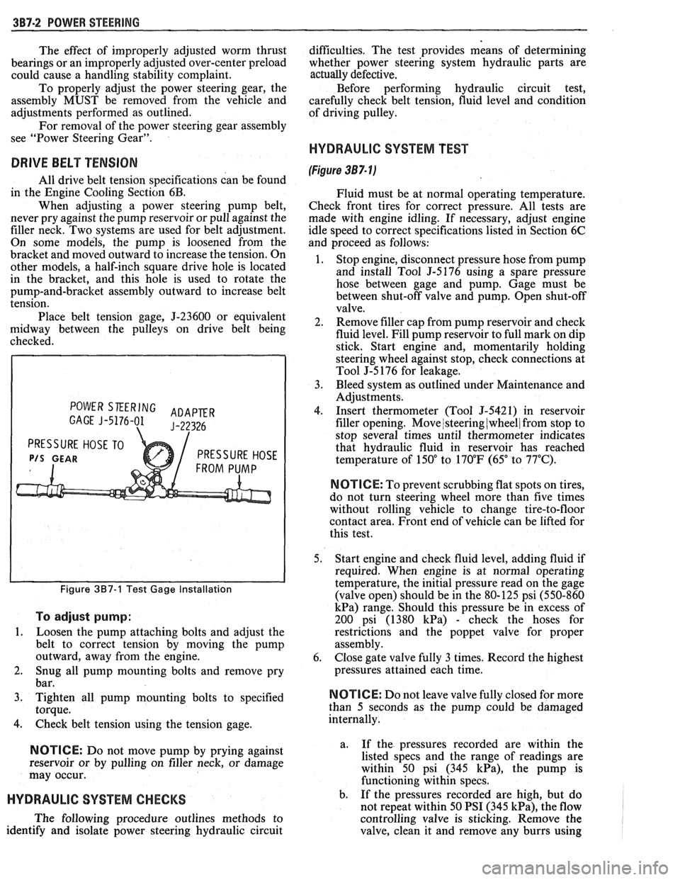
POWER SKERING ADAPER GAGE J-5176-01 J-22326
PRESSURE HOSE TO
P/S GEAR PRESSURE HOSE
Figure 387-1 Test Gage Installation
To adjust pump:
1.
Loosen the pump attaching bolts and adjust the
belt to correct tension by moving the pump
outward, away from the engine.
2. Snug all pump mounting bolts and remove pry
bar.
3. Tighten all pump mounting bolts to specified
torque.
4. Check belt tension using the tension gage.
NOTICE: Do not move pump by prying against
reservoir or by pulling on filler neck, or damage
may occur.
HYDRAULIC SYSTEM CHECKS
The following procedure outlines methods to
identify and isolate power steering hydraulic circuit difficulties.
The test provides means of determining
whether power steering system hydraulic parts are
actually
defective.
Before performing hydraulic circuit test,
carefully check belt tension, fluid level and condition
of driving pulley.
HYDRAULIC SYSTEM TEST
(Figure 387- lj
Fluid must be at normal operating temperature.
Check front tires for correct pressure. All tests are
made with engine idling. If necessary, adjust engine
idle speed to correct specifications listed in Section 6C
and proceed as follows:
1. Stop engine, disconnect pressure hose from pump
and install Tool
5-5176 using a spare pressure
hose between gage and pump. Gage must be
between shut-off valve and pump. Open shut-off
valve.
2. Remove filler cap from pump reservoir and check
fluid level. Fill pump reservoir to full mark on dip
stick. Start engine and, momentarily holding
steering wheel against stop, check connections at
Tool J-5 176 for leakage.
3. Bleed system as outlined under Maintenance and
Adjustments.
4. Insert thermometer (Tool J-5421) in reservoir
filler opening. Move
/steering (wheel/ from stop to
stop several times until thermometer indicates
that hydraulic fluid in reservoir has reached
temperature of
150" to 170°F (65" to 77°C).
N OTI G E: To prevent scrubbing flat spots on tires,
do not turn steering wheel more than five times
without rolling vehicle to change tire-to-floor
contact area. Front end of vehicle can be lifted for
this test.
5. Start engine and check fluid level, adding fluid if
required. When engine is at normal operating
temperature, the initial pressure read on the gage
(valve open) should be in the 80-125 psi (550-860
kPa) range. Should this pressure be in excess of
200 psi (1380
kPa) - check the hoses for
restrictions and the poppet valve for proper
assembly.
6. Close gate valve fully
3 times. Record the highest
pressures attained each time.
N OTI C E: Do not leave valve fully closed for more
than
5 seconds as the pump could be damaged
internally.
a. If
the pressures recorded are within the
listed specs and the range of readings are
within 50 psi (345
kPa), the pump is
functioning within specs.
b. If the pressures recorded are high, but do
not repeat within 50 PSI (345
kPa), the flow
controlling valve is sticking. Remove the
valve, clean it and remove any burrs using
Page 196 of 1825
POWER STEERING 387-3
crocus cloth or fine hone. If the system 4. If the pump checks within specifications, leave
contains some dirt, flush it. If it is the valve open and turn (or have turned) the
exceptionally dirty, both the pump and the steering wheel into both corners. Record the
gear must be completely disassembled, highest pressures and compare with the
cleaned, flushed and reassembled before maximum pump pressure recorded. If this
further usage. pressure cannot be built in either (or one) side of
- the gear, the gear is leaking internally and must
c. If
the pressures recorded are constant, but
be disassembled and repaired. See "Unit Repair"
more than
100 PSI (690 kPa), below the
at the end of this section.
spec.9 rep1ace the flow 8. Shut off engine, remove testing gage, spare hose,
valve and recheck. If the pressures are still
low, replace the rotating group in the pump. reconnect pressure hose, check fluid
level and/or
make needed repairs.
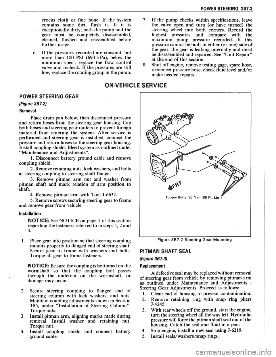
ON-VEHICLE SERVICE
POWER STEERING GEAR
(Figure 387-2)
Removal
Place drain pan below, then disconnect pressure
and return hoses from the steering gear housing. Cap
both hoses and steering gear outlets to prevent foreign
material from entering the system. After service is
performed and steering gear is installed, connect the
pressure and return hoses to the steering gear housing.
Install coupling shield. Bleed system as outlined under
"Maintenance and Adjustments".
1. Disconnect battery ground cable and remove
coupling shield.
2. Remove retaining nuts, lock washers, and bolts
at steering coupling to steering shaft flange.
3. Remove pitman arm nut and washer from
pitman shaft and mark relation of arm position to
shaft.
4. Remove pitman arm with Tool J-6632.
5.
Remove screws securing steering gear to frame
and remove gear from vehicle.
Installation
NOTICE: See NOTICE on page 1 of this section
regarding the fasteners referred to in steps 1,2 and
3.
1. Place gear into position so that steering coupling
mounts properly to flanged end of steering shaft.
Secure gear to frame with washers and bolts.
Torque all gear to frame fasteners.
NOTICE: Be sure the coupling is bottomed on the
wormshaft so that the coupling bolt passes
through the undercut on the wormshaft, or
damage may occur.
2. Secure steering coupling to flanged end of
steering column with lock washers, and nuts.
Maintain coupling adjustments shown in Section
3B5, under "Installation of Steering Column".
Torque nuts.
3. Install pitman arm, aligning marks made during
removal. Install washer and retaining nut.
Torque nut.
4. Install coupling shield and connect battery
ground cable.
Torque Bolts: 90 Nm (66 Ft. ~bs.r
Figure 3B7-2 Steering Gear Mounting
PITMAN SHAFT SEAL
(Figure 387-3)
Replacement
A defective seal may be replaced without removal
of steering gear from vehicle by removing
pitman arm
as outlined under Maintenance and Adjustments
-
Steering Gear Adjustments. Proceed as follows:
1. Clean end of housing to prevent contamination.
2. Remove retaining
ring with snap ring pliers
J-4245.
3. With rear wheels off the ground, start the engine,
turn the steering wheel all the way left. Hydraulic
pressure will force the
pitman shaft seal out of the
housing. Catch the seal and fluid in a pan.
4. Stop engine, install a new seal using 5-6219.
5. Install seals/washers/snap rings.