set clock PONTIAC FIERO 1988 Service Repair Manual
[x] Cancel search | Manufacturer: PONTIAC, Model Year: 1988, Model line: FIERO, Model: PONTIAC FIERO 1988Pages: 1825, PDF Size: 99.44 MB
Page 60 of 1825
AIR CONDITIONING 1B-17
If prescribed vacuum cannot be reached, close
vacuum control valve, shut off pump and look
for a leak at connections or pump.
3. When gauge reaches prescribed vacuum, the
system is fully evacuated. Close the high-side
gauge set valve and turn off the vacuum pump.
4. Watch low-side gauge to be sure vacuum holds
for five (5) minutes. If vacuum is held, discon-
nect vacuum hose at gauge set and then proceed
to charging.
5. If vacuum does not hold for five (5) minutes,
charge system with
420ml(1/2 pound) Refriger-
ant-12 and leak check. Discharge system again
and repair leak as necessary. Repeat evacuation
procedure.
To Begin Charging of the NC System
1. Start engine and set A/C mode control button on
"OFF. "
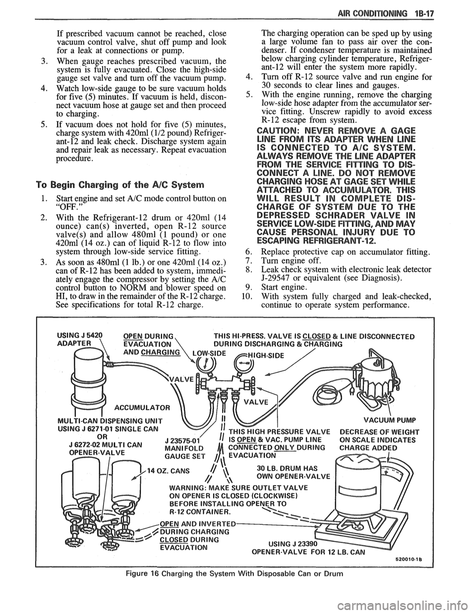
2. With the Refrigerant-12 drum or 420ml (14
ounce)
can(s) inverted, open R-12 source
valve(s) and allow 480ml (1 pound) or one
420m1 (14 02.) can of liquid R-12 to flow into
system through low-side service fitting.
3. As soon as 480ml (1 lb.) or one 420ml (14 oz.)
can of R-12 has been added to system, immedi-
ately engage the compressor by setting the
A/C
control button to NORM and blower speed on
HI, to draw in the remainder of the R-12 charge.
See specifications for total R-12 charge. The
charging operation can be sped up by using
a large volume fan to pass air over the con-
denser. If condenser temperature is maintained
below charging cylinder temperature,
Refriger-
ant-12 will enter the system more rapidly.
4. Turn off
R-12 source valve and run engine for
30 seconds to clear lines and gauges.
5. With the engine running, remove the charging
low-side hose adapter from the accumulator ser-
vice fitting. Unscrew rapidly to avoid excess
R-12 escape from system.
CAUTION: NEVER REMOVE A GAGE
LINE FROM ITS ADAPEER WHEN LINE
IS CONNECTED TO A/G SYSTEM.
ALWAYS REMOVE
THE LINE ADAPTER
FROM THE
SERVICE F1miNG TO DIS-
CONNECT A LINE. DO
NOT REMOVE
CHARGING
HOSE AT GAGE SET WHILE
ATTACHED TO ACGUMULBTOR. "THIS
WILL RESULT IN COMPLETE DIS-
CHARGE OF SYSTEM DUE TO THE
DEPRESSED SCHRADER VALVE IN
SERVICE LOW-SIDE
F17$TING, AND MAY
CAUSE PERSONAL
INJURY DUE TO
ESCAPING REFRIGERANT-72;.
6. Replace protective cap on accumulator fitting.
7. Turn engine off.
8. Leak check system with electronic leak detector
5-29547 or equivalent (see Diagnosis).
9. Start engine.
10. With system fully charged and leak-checked,
continue to operate system performance.
THIS HI-PRESS. VALVE IS
EVACUATION
ACCUMULATOR
ISPENSING UNIT
30 LB. DRUM HAS
OWN OPENER-VALVE
WARNING: MAKE SURE OUTLET VALVE
ON OPENER IS CLOSED (CLOCKWISE)
R-12 CQNTAINER.
OPEN AND INVERTED
DURING CHARGING
EVACUATION
Figure 16 Charging the System With Disposable Can or Drum
Page 152 of 1825
STEERING WHEELS AND COLUMNS 385.1
SECTION 3B5
STEER NG WHEELS AND COLUMNS
NOTICE: All steering wheel and column fasteners are important attaching parts in that they could affect
the performance of vital parts and systems, and/or could result in major repair expense. They
must be replaced
with one of the same part number or with an equivalent part if
replacement becomes necessary. Do not use a
replacement part of lesser quality or substitute design. 'Torque values must be used as specified during reassembly
to assure proper retention of all parts. There is to be no welding as
it may result in extensive damage and weakening
of the metal.
For prevailing torque
nut(s) and bolts(s), refer to the "Reuse of Prevailing Torque Nut(<) and Bolt(s) " chart
in Section OA.
CONTENTS
..................... ................................................................... GENERAL DESCRIPTION .. 3B5-1 ............................................. ........................ MAINTENANCE AND ADJUSTMENTS .. 3B5-1 ON-CAR SERVICE ........................................................................................................ 3B5-2
Steering Column ............................................................................................................ 3B5-2 ......................................................................................................... Intermediateshaft 3B5-3
Park Lock Cable .................................................................... 3B54 ......................................................................................... Checking For Accident Damage 3B5-5 ............................................................................ Unit Repair Intermediate Shaft Assembly 3B5-6
..................................................................................... Standard Column @lanual Trans) 3B5-7 ......................................................... ....................... Standard Column (Auto Trans) .. 3B5-13 Tilt Column (Manual Trans) ............................................................................................. 3B5-19
Tilt Column (Auto Trans). ................................................................................................ 3B5-27
................ .................... TORQUE SPECIFICATIONS .. .. 3B5-35
SPECIAL TOOLS .......................................................................................................... 3B5-35
GENERAL DESCRIPTION
STEERING COLUMN
The function locking energy absorbing steering
column includes three important features in addition
to the steering function:
1. 'The column is energy absorbing, designed to
compress in a front-end collision to minimize the
possibility of an injury to the driver of the car.
2. The ignition switch and lock are mounted
conveniently on this column.
3. With the column mounted lock, the ignition and
steering operations can be locked to inhibit theft
of the car.
The turn signal lever provides for control of
headlight beams, windshield washer and wipers.
The column may be easily
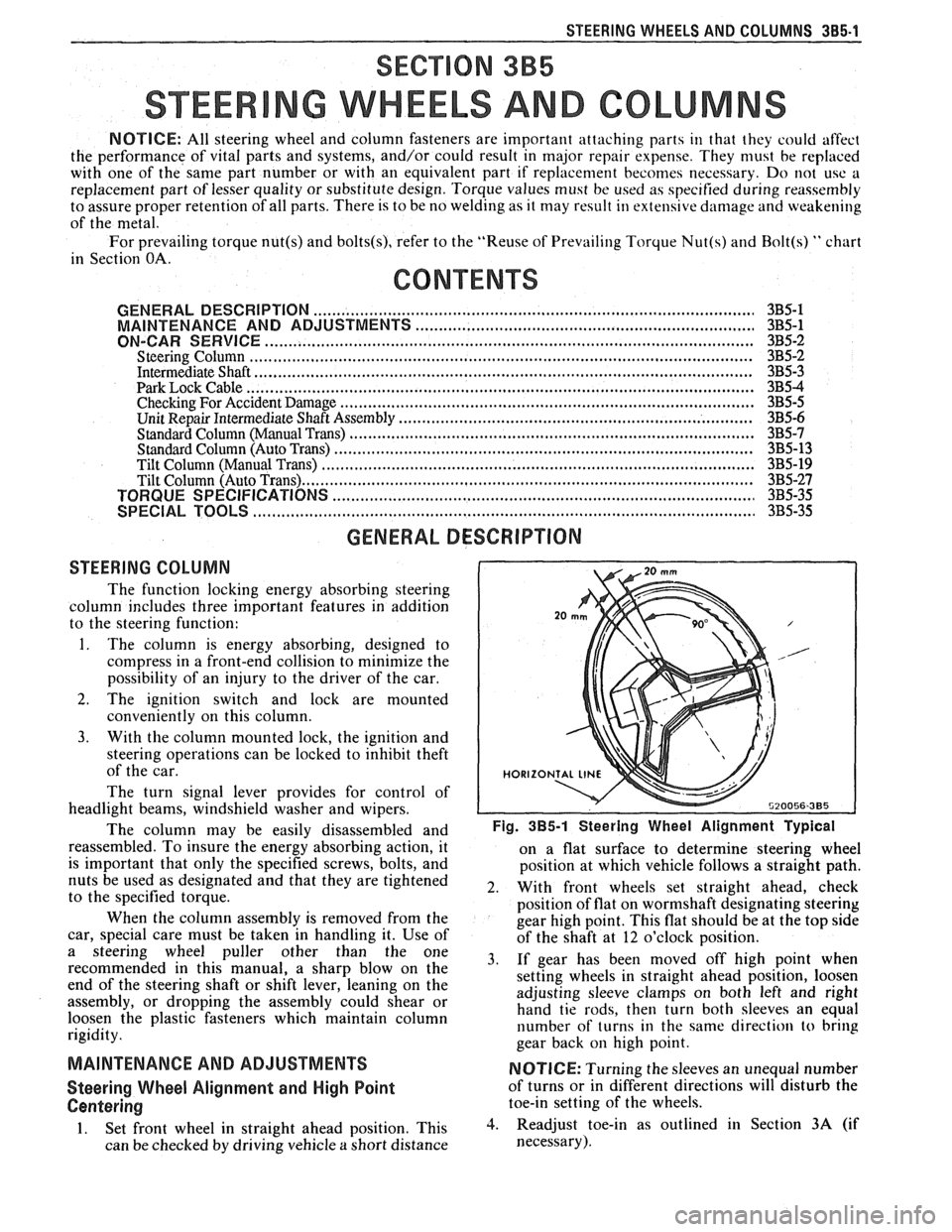
disassembled and Fig. 385-1 Steering Wheel Alignment ~ypical
reassembled. To insure the energy absorbing action, it
on a flat surface to determine steering wheel
is important that only the specified screws, bolts, and
position at which vehicle follows a straight path.
nuts be used as designated and that they are tightened
2. With front wheels set straight ahead, check to the specified torque.
position of flat on wormshaft designating steering
When the column assembly is removed from the
gear high point. This flat should be at the top side
car, special care must be taken in handling it. Use of
of the shaft at 12 o'clock position.
a steering puller other than the One 3, if gear has been moved off high when recommended in this manual, a sharp blow on the
setting wheels in straight ahead position, loosen
end of the steering shaft or shift lever, leaning on the
assembly, or dropping the assembly could shear or adjusting
sleeve clamps on both left and right
hand tie rods, then turn both sleeves an equal
loosen the plastic fasteners which maintain column
rigidity. number
of turns in the same direction
to bring
gear back
on high point.
MAINTENANCE AND ADJUSTMENTS NOTICE: Turning the sleeves an unequal number
Steering Wheel Alignment and High Point of turns or in different directions will disturb the
Centering toe-in setting of the wheels.
1. Set front wheel in straight ahead position, This 3. Readjust toe-in as outlined in Section 3A (if
can be checked by driving vehicle
a short distance necessary).
Page 161 of 1825
385.10 STEERING WHEELS AND COLUMNS
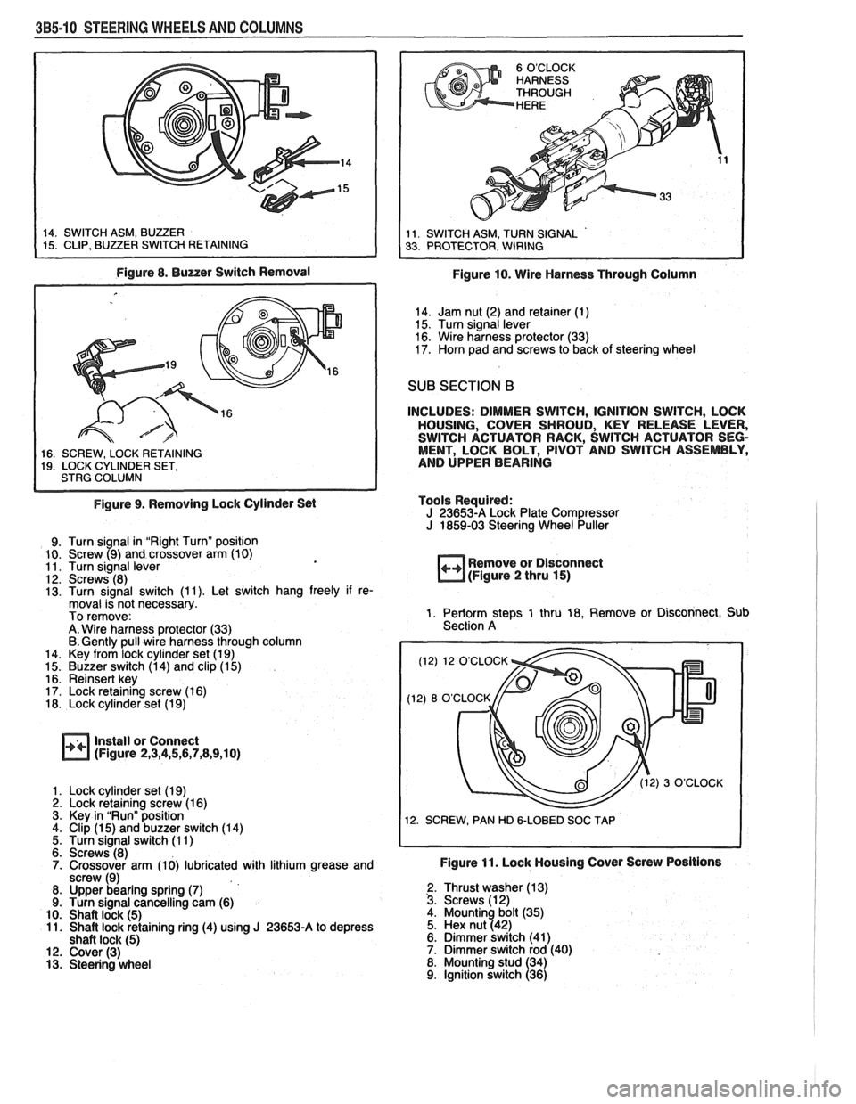
Figure 8. Buzzer Switch Removal
1 16. SCREW. LOCK RETAINING I 19. LOCK CYLINDER SET, I STRG COLUMN I
Figure 9. Removing Lock Cylinder Set
9. Turn signal in "Right Turn" position
10. Screw (9) and crossover arm (10)
11. Turn signal lever
12. Screws (8)
13. Turn signal switch (1 1). Let switch hang freely if re-
moval is not necessary.
To remove:
A. Wire harness protector (33)
6. Gently pull wire harness through column
14. Key from lock cylinder set (1 9)
15. Buzzer switch (1 4) and clip (1 5)
16. Reinsert key
17. Lock retaining screw (1 6)
18. Lock cylinder set (1 9)
Install or Connect
(Figure 2,3,4,5,6,7,8,9,10)
1. Lock cylinder set (1 9) 2. Lock retaining screw (1 6)
3. Key in "Run" position
4. Clip
(1 5) and buzzer switch (1 4)
5. Turn signal switch (1 1)
6. Screws (8)
7. Crossover arm (10) lubricated with lithium grease and
screw (9)
8. Upper bearing spring
(7) 9. Turn signal cancelling cam (6)
10. Shaft lock (5) 11. Shaft lock retaining ring (4) using J 23653-A to depress
shaft lock (5) 12. Cover (3) 13. Steering wheel
Figure 10. Wire Harness Through Column
14. Jam nut (2) and retainer (1)
15. Turn signal lever
16. Wire harness protector (33)
17. Horn pad and screws to back of steering wheel
SUB SECTION B
INCLUDES: DIMMER SWITCH, IGNITION SWITCH, LOCK
HOUSING, COVER SHROUD, KEY RELEASE LEVER,
SWITCH ACTUATOR RACK, SWITCH ACTUATOR SEG-
MENT, LOCK BOLT, PIVOT AND SWITCH ASSEMBLY,
AND UPPER BEARING
Tools Required:
J 23653-A Lock Plate Compressor J 1859-03 Steering Wheel Puller
++ Remove or Disconnect
(Figure 2 thru 15)
1. Perform steps 1 thru 18, Remove or Disconnect, Sub
Section A
(12) 12 O'CLOCK
12. SCREW, PAN HD
&LOBED SOC TAP
Figure 11. Lock Housing Cover Screw Positions
2. Thrust washer (1 3) 3. Screws (1 2)
4. Mounting bolt (35)
5. Hex nut (42)
6. Dimmer switch (41)
7. Dimmer switch rod (40)
8. Mounting stud (34)
9. Ignition switch (36)
Page 287 of 1825
4B-14 REAR AXLE
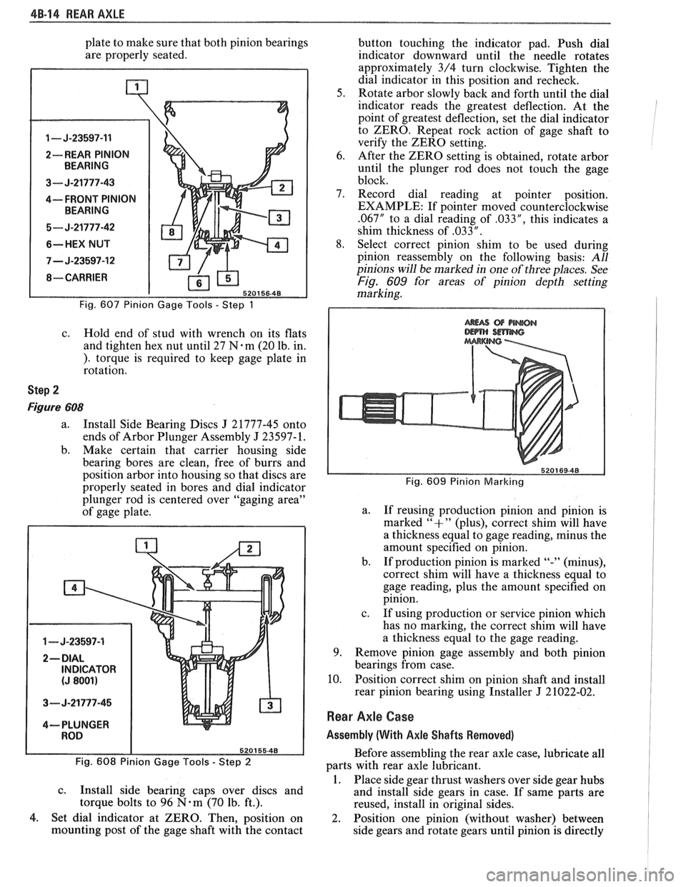
plate to make sure that both pinion bearings
are properly seated.
1 - J-23597-11
2-- REAR PINION
3--- J-21777-43
4---- FRONT PINION
5- J-21777-42
6-HEX NUT
7 - J-23597-12
Fig. 607 Pinion Gage Tools - Step 1
c. Hold end of stud with wrench on its flats
and tighten hex nut until 27
N.m (20 lb. in.
). torque is required to keep gage plate in
rotation.
Step 2
Figure 608
a. Install Side Bearing Discs J 21777-45 onto
ends of Arbor Plunger Assembly
J 23597- 1.
b. Make certain that carrier housing side
bearing bores are clean, free of burrs and
position arbor into housing so that discs are
properly seated in bores and dial indicator
plunger rod is centered over "gaging area"
of gage plate.
1 - J-23597-4
3- J-21777-45
4--- PLUNGER
Fig. 608 Pinion Gage Tools
- Step 2
c.
Install side bearing caps over discs and
torque bolts to 96
N-m (70 lb. ft.).
4. Set dial indicator at ZERO. Then, position on
mounting post of the gage shaft with the contact button
touching the indicator pad. Push dial
indicator downward until the needle rotates
approximately 3/4 turn clockwise. Tighten the
dial indicator in this position and recheck.
5. Rotate arbor slowly back and forth until the dial
indicator reads the greatest deflection. At the
point of greatest deflection, set the dial indicator
to ZERO. Repeat rock action of gage shaft to
verify the ZERO setting.
6. After the ZERO setting is obtained, rotate arbor
until the plunger rod does not touch the gage
block.
7. Record dial reading at pointer position.
EXAMPLE: If pointer moved counterclockwise
.067" to a dial reading of .033", this indicates a
shim thickness of
,033 " .
8. Select correct pinion shim to be used during
pinion reassembly on the following basis:
All
pinions will be marked in one of three places. See
Fig. 609 for areas of pinion depth setting
marking.
Fig. 609 Pinion Marlcing
a.
If reusing production pinion and pinion is
marked
"+" (plus), correct shim will have
a thickness equal to gage reading, minus the
amount specified on pinion.
b. If production pinion is marked
"-" (minus),
correct shim will have
a thickness equal to
gage reading, plus the amount specified on
pinion.
c. If using production or service pinion which
has no marking, the correct shim will have
a thickness equal to the gage reading.
9. Remove pinion gage assembly and both pinion
bearings from case.
10. Position correct shim on pinion shaft and install
rear pinion bearing using Installer
J 21022-02.
Rear Axle Case
Assembly (With Axle Shafts Removed)
Before assembling the rear axle case, lubricate all
parts with rear axle lubricant.
1. Place side gear thrust washers over side gear hubs
and install side gears in case. If same parts are
reused, install in original sides.
2. Position one pinion (without washer) between
side gears and rotate gears until pinion is directly
Page 368 of 1825
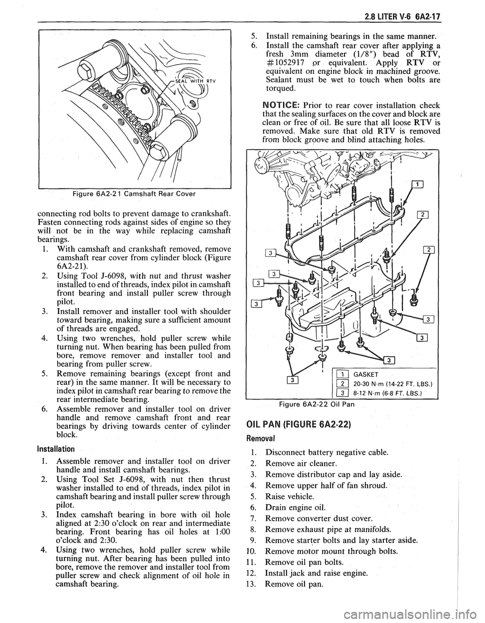
2.8 LITER V-6 6A2-17
Figure 6A2-2 1 Camshaft Rear Cover
connecting rod bolts to prevent damage to crankshaft.
Fasten connecting rods against sides of engine so they
will not be in the way while replacing camshaft
bearings.
1. With camshaft and crankshaft removed, remove
camshaft rear cover from cylinder block (Figure
6A2-2 1).
2. Using Tool J-6098, with nut and thrust washer
installed to end of threads, index pilot in camshaft
front bearing and install puller screw through
pilot.
3. Install remover and installer tool with shoulder
toward bearing, making sure a sufficient amount
of threads are engaged.
4. Using two wrenches, hold puller screw while
turning nut. When bearing has been pulled from
bore, remove remover and installer tool and
bearing from puller screw.
5. Remove remaining bearings (except front and
rear) in the same manner. It will be necessary to
index pilot in camshaft rear bearing to remove the
rear intermediate bearing.
6. Assemble remover and installer tool on driver
handle and remove camshaft front and rear
bearings by driving towards center of cylinder
block.
Installation
1. Assemble remover and installer tool on driver
handle and install camshaft bearings.
2. Using Tool Set J-6098, with nut then thrust
washer installed to end of threads, index pilot in
camshaft bearing and install puller screw through
pilot.
3. Index camshaft bearing in bore with oil hole
aligned at
2:30 o'clock on rear and intermediate
bearing. Front bearing has oil holes at
1:00
o'clock and 230.
4. Using two wrenches, hold puller screw while
turning nut. After bearing has been pulled into
bore, remove the remover and installer tool from
puller screw and check alignment of oil hole in
camshaft bearing.
5. Install remaining bearings in the same manner.
6. Install the camshaft rear cover after applying a
fresh 3mm diameter
(1/8") bead of RTV,
#I052917 .or equivalent. Apply RTV or
equivalent on engine block in machined groove.
Sealant must be wet to touch when bolts are
torqued.
NOTICE: Prior to rear cover installation check
that the sealing surfaces on the cover and block are
clean or free of oil. Be sure that all loose RTV is
removed. Make sure that old RTV is removed
from block groove and blind attaching holes.
&'p-x&F--
1 20-30 N~rn (14-22 FT. LBS.)
Figure 6A2-22 Oil Pan
OIL PAN (FIGURE 6A2-22)
Removal
1. Disconnect battery negative cable.
2. Remove air cleaner.
3. Remove distributor cap and lay aside.
4. Remove upper half of fan shroud.
5. Raise vehicle.
6. Drain engine oil.
7. Remove converter dust cover.
8. Remove exhaust
pipe at manifolds.
9. Remove starter bolts and lay starter aside.
10. Remove
motor mount through bolts.
1 1. Remove oil pan bolts.
12. Install jack and raise engine.
13. Remove oil pan.
Page 397 of 1825
6A3-18 V-8 ENGINE
bore, remove remover and installer tool and
bearing from puller screw.
5. Remove remaining bearings (except front and
rear) in the same manner. It will be necessary to
index pilot in camshaft rear bearing to remove the
rear intermediate bearing.
6. Assemble remover
and installer tool on driver
handle and remove camshaft front and rear
bearings by driving towards center of cylinder
block.
lnstallation
The camshaft front and rear bearings should be
installed first. These bearings will act as guides for the
pilot and center the remaining bearings being pulled
into place.
1. Assemble remover
and installer tool on driver
handle and install camshaft front and rear
bearings by driving towards center of cylinder
block.
2. Using Tool Set J-6098, with nut then thrust
washer installed to end of threads, index pilot in
camshaft front bearing and install puller screw
through pilot.
3. Index camshaft bearing in bore (with oil hole
aligned as outlined below), then install remover
and installer tool on puller screw with shoulder
toward bearing.
e Number one cam bearing oil hole must be
positioned so that oil holes are equidistant
from 6 o'clock position.
e Number two through number four bearing
oil holes must be positioned at 5 o'clock
position (toward left side of engine and at a
position even with bottom of cylinder bore).
e Number five bearing oil hole must be in 12
o'clock position.
4. Using two wrenches, hold puller screw while
turning nut. After bearing has been pulled into
bore, remove the remover and installer tool from
puller screw and check alignment of oil hole in
camshaft bearing.
5. Install remaining bearings in the same manner. It
will be necessary to index pilot in the camshaft
rear bearing to install the rear intermediate
bearing.
6. Coat new camshaft rear plug O.D. with
# 1052080 sealant, or equivalent, and install
flush to 1/32"
(.80mm) deep.
OIL PAN
Removal
1. Disconnect battery negative cable.
2. Remove fan shroud.
3. Remove air cleaner and lay aside if equipped.
4. Remove distributor cap and lay aside.
5. Raise vehicle.
6. Drain crankcase.
7. Disconnect exhaust pipe at manifold.
8. Disconnect AIR pipe clamp.
9. Disconnect converter hanger bolts and allow
exhaust to hang down.
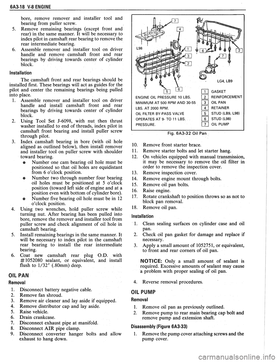
GASKET
ENGINE OIL PRESSURE 10 LBS.
1 REINFORCEMENT
MINIMUM AT 500 RPM AND 30-55
1 OIL PAN
LBS. AT 2000 RPM.
161 RETAINER
OIL FILTER BY-PASS VALVE STUD
(LB9, L98)
OPERATES
AT 9- TO 11 LBS. STUD (L98)
PRESSURE.
OIL PUMP
Fig. 6A3-32 Oil Pan
10. Remove front starter brace.
11. Remove starter bolts and let starter hang.
12. On vehicles equipped with manual transmission,
it may be necessary to remove the oil filter in
order to remove the inspection cover.
13. Remove inspection cover.
14. Remove engine mount through bolts.
15. Remove oil pan bolts.
16. Raise engine.
17. Rotate crankshaft to position throws so as not to
block pan removal.
18. Remove oil pan.
lnstallation
1.
Clean sealing surfaces on cylinder case and oil
pan.
2. Check oil pan gasket for damage and replace if
necessary.
3. Apply a small amount of 1052751, or equivalent,
to front and rear corners of oil pan.
NOTICE: Only a small amount of sealant is
required. Excessive amounts of sealant may cause
a problem with proper sealing of oil pan.
4. Reverse removal procedures.
OIL PUMP
Removal
1. Remove oil pan as previously outlined.
2. Remove pump to rear main bearing cap bolt and
remove pump and extension shaft.
Disassembly (Figure 6A3-33)
1. Remove the pump cover attaching screws and the
pump cover.
Page 418 of 1825
ENGINE COOLING BB-7
NOTICE: If recommended quality antifreeze is
used, supplemental inhibitors or additives claiming
to provide increased cooling capability are not
necessary. They may be detrimental to the efficient
operation of the system, and represent an
unnecessary operating expense.
Every 12 months or 15,000 miles, the cooling
system should be serviced as follows;
1. Wash radiator cap and filler neck with clean
water.
2. Check coolant for proper level and freeze
protection.
3. Pressure test system and radiator cap for proper
pressure holding capacity, 103
kPa (15 psi). If
replacement of cap is required, use the proper cap
specified for car model.
4. Tighten hose clamps and inspect all hoses. Replace
hoses whenever cracked, swollen or otherwise
deteriorated.
5. Clean frontal area of radiator core and air
conditioning condenser.
DRAINING AND REFILLING THE COOLING
SYSTEM
Replace hoses every 24 months or 30,000 miles or
earlier if cracked, swollen or otherwise deteriorated.
Every two years or 30,000 miles, whichever first
occurs, the cooling system should be flushed and
refilled using the following recommended procedure:
1. Remove radiator cap, or thermostat housing cap
(VIN
0, J, R and U), when engine is cool by:
a. Slowly
rotating cap counterclockwise to
detent. (Do not press down while rotating.)
b. Wait until any
residual pressure (indicated
by a hissing sound) is relieved.
c. After all hissing ceases, press down on cap
while continuing to rotate
counterclockwise.
CAUTION: To avoid the danger of
being burned, do not remove radiator
cap while engine and radiator are still
hot. Scalding fluid and steam may be
blown out under pressure.
2. Remove the thermostat by using the wire handle
to lift it out of the housing (VIN
0, J, R and U).
3. With the thermostat removed, reinstall the
thermostat housing cap (VIN
0, J, R and U).
4. Open radiator drain valve and block drain plugs
to drain coolant. On VIN R and
9 (P series)
engines, open coolant pipe plugs.
5. Close valve. Reinstall drain plugs, and add
sufficient water to fill system.
6. Run engine, drain and refill the system, as
described in steps
4 and 5 a sufficient number of
times, until the drained liquid is nearly colorless.
Important
BLOCK DRIVE WHEELS, place
transmission in PARK (automatic
transmission) or NEUTRAL (manual
transmission) and set the parking brake. 7.
Allow system to drain completely. Then close
radiator drain valve tightly, and reinstall block
drain plugs.
8. Remove recovery cap leaving hoses in place.
Remove coolant recovery tank and empty of
fluid. Flush tank with clean water, drain and
reinstall.
9. Add sufficient ethylene glycol coolant, meeting
GM specification 1825-M, to provide the
required freezing and corrosion protection
- at
least 50 percent solution -37°C (-34°F). Fill
radiator to the base of the radiator fill neck and
add sufficient coolant to the recovery tank to
raise level to the "FULL" mark. Reinstall
recovery tank cap.
10. Run engine, with radiator cap or thermostat
housing cap removed, until normal operating
temperature is reached. (Radiator upper hose
becomes hot.)
11. With engine idling, add coolant until level
reaches bottom of filler neck and reinstall cap,
making certain arrows line up with overflow tube.
CAUTION: Under some conditions, the
ethylene glycol in engine coolant is
flammable. To help avoid being
burned when adding coolant, DO NOT
spill
it on the exhaust system or hat
engine parts.
It is the owner's responsibility to keep the freeze
protection at a level appropriate to the
temperatures which may occur in the area of
vehicle operation.
a. Maintain
cooling system freeze protection
at
-37°C (-34"F), to ensure protection
against corrosion and loss of coolant from
boiling, even though freezing temperatures
are not expected.
b. Add ethylene glycol base coolant that meets
GM Specification 1825-M, when coolant
additions are required because of coolant
loss, or to provide additional protection
against
freezing at temperatures lower than
-37°C (-34°F).
NOTICE: Alcohol or methanol base coolants, or
plain water, are not recommended at any time.
DRlVE BELT
NOTICE: Routine inspection of the belt may
reveal cracks in the belt ribs. These cracks will
not impair belt performance and therefore should
not be considered a problem requiring belt
replacement. However, the belt should be
replaced if belt slip occurs or if sections of the
belt ribs are missing.
A single (serpentine) belt is used to drive all
engine accessories formerly driven by multiple drive
belts. All belt driven accessories are ridgedly mounted
with belt tension maintained by a spring loaded
tensioner.
The drive belt tensioner has the ability to control
belt tension over a fairly broad range of belt lengths.
Page 473 of 1825
684.4 IGNITION SYSTEM
a spark plug wire from a spark plug, twist the 4. Do not wipe grease from module, or distributor
boot on the spark plug and pull
on the boot to base,
if same module is to be replaced.
remove the wire, or use a special tool designed to
remove spark plug boots.
Install or Connect
Remove or Disconnect
1. Ignition switch battery feed wire and tachometer
lead (if equipped) from distributor cap. Also
release the coil connectors from the cap. (DO
NOT use a screwdriver or tool to release the
locking tabs.)
2. Distributor cap by turning four screws
counterclockwise. Move cap out of the way.
3. Four-terminal ECM harness from distributor.
4. If necessary, remove secondary wires from cap,
release wiring harness latches and remove wiring
harness retainer. The spark plug wire numbers
are indicated on the retainer.
5. Distributor clamp screw and hold-down clamp.
6. Note position of rotor, then pull distributor up
until rotor just stops turning counterclockwise
and again note position of rotor.
To insure correct timing of the distributor,
the distributor must be INSTALLED with
the rotor correctly positioned as noted.
If the engine was accidentally cranked after the
distributor was removed, the following procedure can
be used for installing:
1. Remove No. 1 spark plug.
2. Place finger over No. 1 spark plug hole and crank
engine slowly until compression is felt.
3. Align timing mark on pulley to "0" on engine
timing indicator.
4. Turn rotor to point between No. 1 and No. 8
spark plug towers on distributor cap on V8
engines, between No. 1 and No. 6 on V6 engines,
and No.
1 and No. 4 on 4 cylinder engines.
5. Install distributor and connect ignition feed wire.
6. Install distributor cap and spark plug wires.
7. Check engine timing (see Set Ignition Timing).
Install or Connect
1. Insert distributor, positioning rotor as removed.
2. Distributor hold-down clamp and screw.
3. Wiring harness retainer and secondary wires, if
removed.
4. ECM harness connector.
5. Distributor cap.
6. Coil connectors.
7. Battery wire and tachometer lead, if equipped.
Module
It is not necessary to remove the distributor from
car.
Remove or Disconnect
1. Distributor cap and rotor.
2. Two module attaching screws, and lift module
UP. 3. Leads from module. (Observe color code on leads
as these cannot be interchanged.)
NOTICE: If a new module is to be installed, a
package of silicone grease will be included with it.
Spread the grease on the metal face of the module
and on the distributor base where the module
seats. This grease is necessary for module cooling.
1. Module.
2. Module leads (observe color code).
3. Attaching screws to module.
4. Rotor.
5. Cap.
Pick-Up Coil
1. Remove distributor from car and follow
instructions in Unit Repair, as applicable.
Rotor
Fig. 1
1. Remove distributor cap.
2. The rotor is retained by two screws and is
provided with a slot which fits over a square lug,
,
so that the rotor can be installed in only one
position.
Integral Ignition Coil
Fig. I
Remove or Disconnect
1. Distributor cap.
2. Three coil cover attaching screws, and lift off
cover.
3. Coil attaching screws and lift ignition coil and
leads from cap.
Install or Connect I
1. Coil and attaching screws.
2. Coil leads.
3. Coil cover and attaching screws.
Capacitor
Fig. 1
The capacitor is part of the coil wire harness
assembly. Since the capacitor is used only for radio
noise suppression, it will seldom need replacement.
Remove or Disconnect I
1. Distributor cap and rotor.
2. Capacitor attaching screw and unplug connector
from module. It may help to loosen the module.
Install or Connect I
1. Plug into module.
2. Capacitor and hold-down screw (be sure ground
lead is under screw).
Page 750 of 1825
DRIVEABILITY AND EMISSIONS 2.8L (VIN S) 6E3-CZ-15
NOTICE: Before instal ling new idle air control valve
assembly, the position of its pintle
MUST
be checked. If pintle is extended too far,
damage to the assembly may occur.
Measure
@ Distance from gasket mounting surface of IAC
valve assembly
(70) to tip of pintle, Dimension
"A" in Figure
C2-19.
Adjust
If distance is greater that 28 mm (1 118 in.), reduce -
it as follows:
a. If
IAC valve assembly has
a "collar" around
electrical connector end, use firm hand pressure
on pintle to retract it. (A slight side-to-side motion
may help.)
b. If IAC valve assembly has "no collar", compress
pintle-retaining spring toward body of the IAC
and try to turn pintle clockwise.
@ If pintle will turn, continue turning until
28mm
(1 118 in.) is reached. Return spring to
original position, with straight part of spring
end lined up with flat surface under the pintle
head.
@ If pintle will not turn, use firm hand pressure
to retract it.
Install or Connect
1. New IAC valve assembly gasket (71) on IAC valve
assembly
(70).
2. IAC valve assembly in idle airlvacuum signal
housing assembly
(60).
Tighten
IAC valve assembly to 18N.m (13 ft. Ibs.), with
wrench on hex surface only.
3. Electrical connector at IAC valve assembly (70).
Important
No physical adjustment is made to the IAC
assembly after installation.
IAC resetting occurs
after reinstallation on the vehicle, and is reset
after the engine is started and then the ignition
turned off.
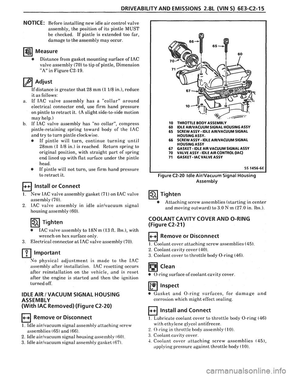
IDLE AIR / VACUUM SIGNAL HOUSING
ASSEMBLY
(With
IAC Removed) (Figure C2-20)
Remove or Disconnect
1. Idle airlvacuurn signal assembly attaching screw
assemblies
(65) and (66).
2. Idle airlvacuum signal housing assembly (60).
3. Idle airlvacuum signal assembly gasket (67).
10 THROTTLE BODY ASSEMBLY
60 IDLE AIWVACUUM SIGNAL
HOUSING ASSY
65 SCREW ASSY - IDLE AIWVACUUM SIGNAL
HOUSING ASSY.
66 SCREW
ASSY
- IDLE AIWVACUUM SIGNAL
HOUSING ASSY
67 GASKET - IDLE AIR VACUUM SIGNAL ASSY 70 VALVE ASSY - IDLE AIR CONTROL (IAC) 71 GASKET - IAC VALVE ASSY
Figure C2-20 Idle AirIVacuum Signal Housing
Assembly
Tighten
@ Attaching screw assemblies (starting in center
and
moving outward) to 3.0 N.m (27.0 in. Ibs.).
COOLANT CAVITY COVER AND O-RING
(Figure
C2-21)
Remove or Disconnect
1. Coolant cover attaching. screw assemblies (45).
2. Coolant cavity cover (40).
3. Coolant cover to throttle body O-ring (46).
Inspect
@ Gasket and O-ring surfaces, for damage and
corrosion which might effect sealing.
Install and Connect
1. Lubricate coolant cover to throttle body O-ring (46)
with ethylene glycol antifreeze.
2. O-ring in throttle body assembly (10).
:3. Coolant cavity cover.
4. Coolant cover attaching screw assemblies (451,
applying pressure against throttle body (1 0).
Page 900 of 1825
DRIVEABILITY AND EMISSIONS 5.OL (VIN F) & 5.7b (VIN 8) 6E3-CZ-13
IDLE STOP SCREW
ASSEMBLY
IDLE STOP
SCREW PLUG
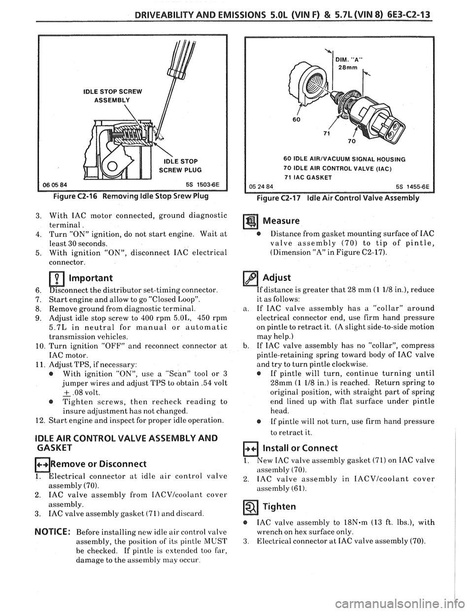
Figure C2-16 Removing Idle Stop Srew Plug
60 IDLE AIR/VACUUM SIGNAL HOUSING
70 IDLE AIR CONTROL VALVE (IAC)
71 IAC GASKET
Figure C2-17 Idle Air Control Valve Assembly
3. With IAC motor connected, ground diagnostic
terminal. Measure
4. Turn "ON" ignition, do not start engine. Wait at @ Distance from gasket mounting surface of IAC
least 30 seconds. valve assembly
(70) to tip of pintle,
5. With ignition
"ON", disconnect IAC electrical (Dimension
"A" in Figure C2-17).
connector.
Important
6. Disconnect
the distributor set-timing connector.
7. Start
engine and allow to go "Closed Loop".
8. Remove
ground from diagnostic terminal.
9. Adjust idle stop screw to 400 rpm 5.01,, 450 rpm
5.7L in neutral for manual or automatic
transmission vehicles.
10. Turn ignition "OFF" and reconnect connector at
IAC motor.
11. Adjust TPS, if necessary:
@ With ignition "ON", use a "Scan" tool or 3
jumper wires and adjust TPS to obtain .54 volt
+ .08 volt. - @ Tighten screws, then recheck reading to
insure adjustment has not changed.
12. Start engine and inspect for proper idle operation.
IDLE AIR CONTROL VALVE ASSEMBLY AND
CASKET
ORemove or Disconnect
1. Electrical connector at idle air control valve
assembly (70).
2. IAC valve assembly from IACVIcoolant cover
assembly.
3. IAC valve assembly gasket (71) and discard.
NOTICE: Before installing new idle air control valve
assembly, the position of its
pinlle MUST
be checked. If pintle is extended too far,
damage to the assembly
may occur
Adjust
If distance is greater that 28 mm (1 118 in.), reduce
it as follows:
a. If IAC valve assembly has a "collar" around
electrical connector end, use firm hand pressure
on pintle to retract it. (A slight side-to-side motion
may help.)
b. If
IAC valve assembly has no "collar", compress
pintle-retaining spring toward body of IAC valve
and try to turn pintle clockwise.
@ If pintle will turn, continue turning until
28mm
(1 118 in.) is reached. Return spring to
original position, with straight part of spring
end lined up with flat surface under pintle
head.
@ If pintle will not turn, use firm hand pressure
to retract it.
Install or Connect
1. New IAC valve assembly gasket (71) on IAC valve
assembly
(70).
2. IAC valve assembly in IACVIcoolant cover
assembly (61).
Tighten
IAC valve assembly to 18N.m (13 ft. Ibs.), with
wrench on hex surface only.
3. Electrical connector at IAC valve assembly (70).