remote start PONTIAC VIBE 2010 Owners Manual
[x] Cancel search | Manufacturer: PONTIAC, Model Year: 2010, Model line: VIBE, Model: PONTIAC VIBE 2010Pages: 318, PDF Size: 1.7 MB
Page 5 of 318
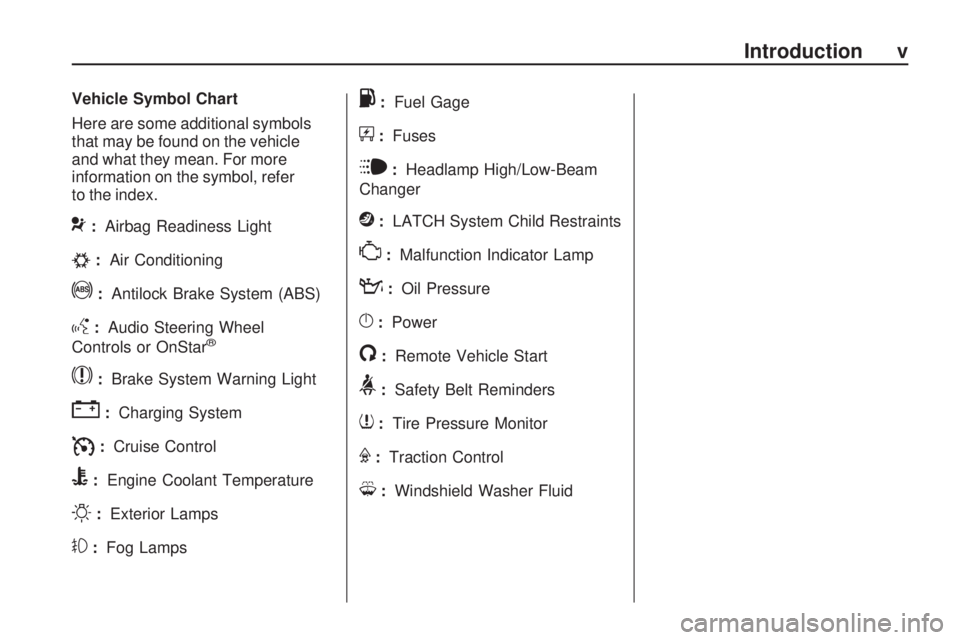
Vehicle Symbol Chart
Here are some additional symbols
that may be found on the vehicle
and what they mean. For more
information on the symbol, refer
to the index.
9:Airbag Readiness Light
#:Air Conditioning
!:Antilock Brake System (ABS)
g:Audio Steering Wheel
Controls or OnStar®
$: Brake System Warning Light
":Charging System
I:Cruise Control
B:Engine Coolant Temperature
O:Exterior Lamps
#:Fog Lamps
.:Fuel Gage
+:Fuses
i:Headlamp High/Low-Beam
Changer
j: LATCH System Child Restraints
*:Malfunction Indicator Lamp
::Oil Pressure
}:Power
/:Remote Vehicle Start
>:Safety Belt Reminders
7:Tire Pressure Monitor
F:Traction Control
M:Windshield Washer Fluid
Introduction v
Page 14 of 318
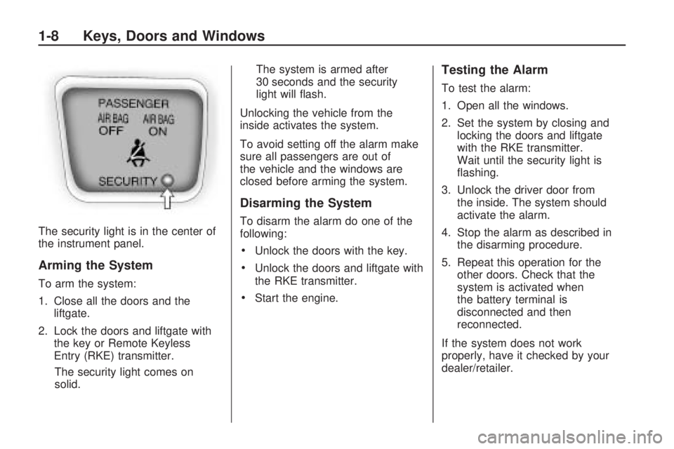
The security light is in the center of
the instrument panel.
Arming the System
To arm the system:
1. Close all the doors and theliftgate.
2. Lock the doors and liftgate with the key or Remote Keyless
Entry (RKE) transmitter.
The security light comes on
solid. The system is armed after
30 seconds and the security
light will flash.
Unlocking the vehicle from the
inside activates the system.
To avoid setting off the alarm make
sure all passengers are out of
the vehicle and the windows are
closed before arming the system.
Disarming the System
To disarm the alarm do one of the
following:
•Unlock the doors with the key.
•Unlock the doors and liftgate with
the RKE transmitter.
•Start the engine.
Testing the Alarm
To test the alarm:
1. Open all the windows.
2. Set the system by closing and locking the doors and liftgate
with the RKE transmitter.
Wait until the security light is
flashing.
3. Unlock the driver door from the inside. The system should
activate the alarm.
4. Stop the alarm as described in the disarming procedure.
5. Repeat this operation for the other doors. Check that the
system is activated when
the battery terminal is
disconnected and then
reconnected.
If the system does not work
properly, have it checked by your
dealer/retailer.
1-8 Keys, Doors and Windows
Page 191 of 318
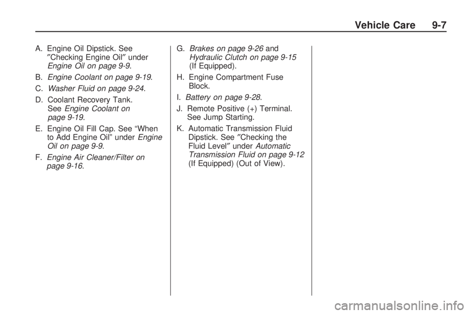
A. Engine Oil Dipstick. See″Checking Engine Oil ″under
Engine Oil on page 9-9 .
B. Engine Coolant on page 9-19 .
C. Washer Fluid on page 9-24 .
D. Coolant Recovery Tank. See Engine Coolant on
page 9-19.
E. Engine Oil Fill Cap. See “When to Add Engine Oil” under Engine
Oil on page 9-9.
F. Engine Air Cleaner/Filter on
page 9-16. G.
Brakes on page 9-26 and
Hydraulic Clutch on page 9-15
(If Equipped).
H. Engine Compartment Fuse Block.
I. Battery on page 9-28 .
J. Remote Positive (+) Terminal. See Jump Starting.
K. Automatic Transmission Fluid Dipstick. See ″Checking the
Fluid Level″ underAutomatic
Transmission Fluid on page 9-12
(If Equipped) (Out of View).
Vehicle Care 9-7
Page 193 of 318
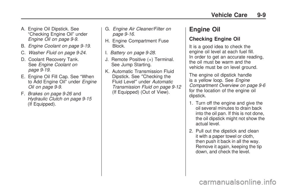
A. Engine Oil Dipstick. See“Checking Engine Oil” under
Engine Oil on page 9-9 .
B. Engine Coolant on page 9-19 .
C. Washer Fluid on page 9-24 .
D. Coolant Recovery Tank. See Engine Coolant on
page 9-19.
E. Engine Oil Fill Cap. See “When to Add Engine Oil” under Engine
Oil on page 9-9.
F. Brakes on page 9-26 and
Hydraulic Clutch on page 9-15
(If Equipped). G.
Engine Air Cleaner/Filter on
page 9-16.
H. Engine Compartment Fuse Block.
I. Battery on page 9-28 .
J. Remote Positive (+) Terminal. See Jump Starting.
K. Automatic Transmission Fluid Dipstick. See ″Checking the
Fluid Level″ underAutomatic
Transmission Fluid on page 9-12
(If Equipped) (Out of View).Engine Oil
Checking Engine Oil
It is a good idea to check the
engine oil level at each fuel fill.
In order to get an accurate reading,
the oil must be warm and the
vehicle must be on level ground.
The engine oil dipstick handle
is a yellow loop. See Engine
Compartment Overview on page 9-6
for the location of the engine oil
dipstick.
1. Turn off the engine and give the oil several minutes to drain back
into the oil pan. If this is not done,
the oil dipstick might not show the
actual level.
2. Pull out the dipstick and clean it with a paper towel or cloth,
then push it back in all the way.
Remove it again, keeping the tip
down, and check the level.
Vehicle Care 9-9
Page 224 of 318
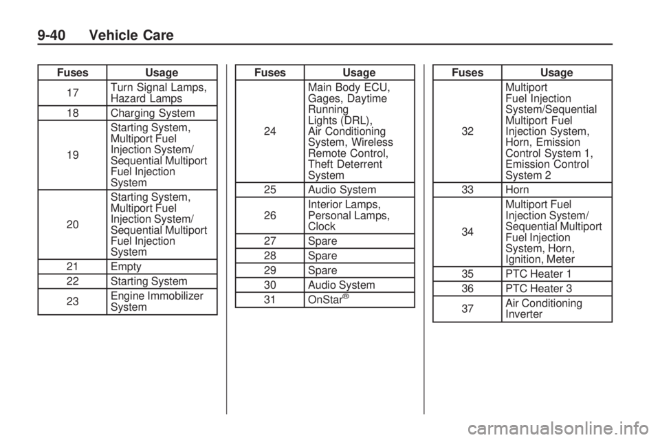
FusesUsage
17 Turn Signal Lamps,
Hazard Lamps
18 Charging System
19 Starting System,
Multiport Fuel
Injection System/
Sequential Multiport
Fuel Injection
System
20 Starting System,
Multiport Fuel
Injection System/
Sequential Multiport
Fuel Injection
System
21 Empty
22 Starting System
23 Engine Immobilizer
SystemFuses
Usage
24 Main Body ECU,
Gages, Daytime
Running
Lights (DRL),
Air Conditioning
System, Wireless
Remote Control,
Theft Deterrent
System
25 Audio System
26 Interior Lamps,
Personal Lamps,
Clock
27 Spare
28 Spare
29 Spare
30 Audio System
31 OnStar
®
Fuses Usage
32 Multiport
Fuel Injection
System/Sequential
Multiport Fuel
Injection System,
Horn, Emission
Control System 1,
Emission Control
System 2
33 Horn
34 Multiport Fuel
Injection System/
Sequential Multiport
Fuel Injection
System, Horn,
Ignition, Meter
35 PTC Heater 1
36 PTC Heater 3
37 Air Conditioning
Inverter
9-40 Vehicle Care
Page 256 of 318
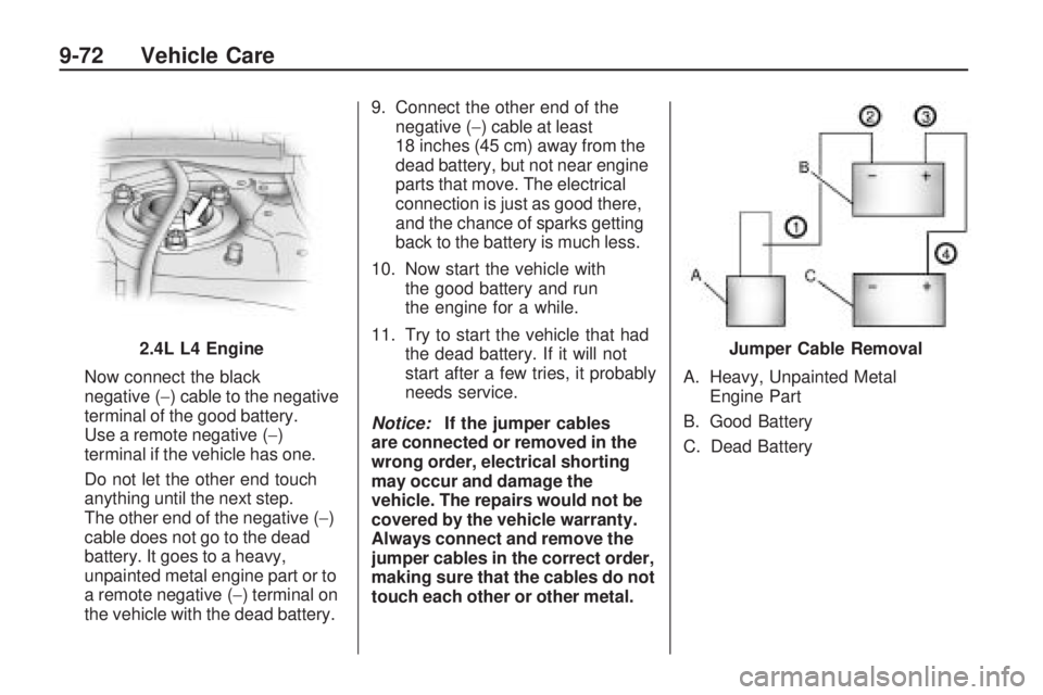
Now connect the black
negative (−) cable to the negative
terminal of the good battery.
Use a remote negative (−)
terminal if the vehicle has one.
Do not let the other end touch
anything until the next step.
The other end of the negative ( −)
cable does not go to the dead
battery. It goes to a heavy,
unpainted metal engine part or to
a remote negative (−) terminal on
the vehicle with the dead battery. 9. Connect the other end of the
negative (−) cable at least
18 inches (45 cm) away from the
dead battery, but not near engine
parts that move. The electrical
connection is just as good there,
and the chance of sparks getting
back to the battery is much less.
10. Now start the vehicle with the good battery and run
the engine for a while.
11. Try to start the vehicle that had the dead battery. If it will not
start after a few tries, it probably
needs service.
Notice: If the jumper cables
are connected or removed in the
wrong order, electrical shorting
may occur and damage the
vehicle. The repairs would not be
covered by the vehicle warranty.
Always connect and remove the
jumper cables in the correct order,
making sure that the cables do not
touch each other or other metal. A. Heavy, Unpainted Metal
Engine Part
B. Good Battery
C. Dead Battery
2.4L L4 Engine
Jumper Cable Removal
9-72 Vehicle Care
Page 308 of 318
Radio Frequency
Identi�cation (RFID)
RFID technology is used in some
vehicles for functions such as tire
pressure monitoring and ignition
system security, as well as in
connection with conveniences such
as key fobs for remote door locking/
unlocking and starting, and in-vehicle
transmitters for garage door openers.
RFID technology in GM vehicles
does not use or record personal
information or link with any other
GM system containing personal
information.
Radio Frequency
Statement (US, Can)
This vehicle has systems that
operate on a radio frequency that
comply with Part 15 of the Federal
Communications Commission (FCC)
Rules and with RSS-210/211 of
Industry and Science Canada.
Operation is subject to the following
two conditions:
1. The device may not causeinterference.
2. The device must accept any interference received, including
interference that may cause
undesired operation of the device.
Changes or modifications to any of
these systems by other than an
authorized service facility could void
authorization to use this equipment.
12-16 Customer Information