tire pressure PONTIAC VIBE 2010 Owners Manual
[x] Cancel search | Manufacturer: PONTIAC, Model Year: 2010, Model line: VIBE, Model: PONTIAC VIBE 2010Pages: 318, PDF Size: 1.7 MB
Page 5 of 318
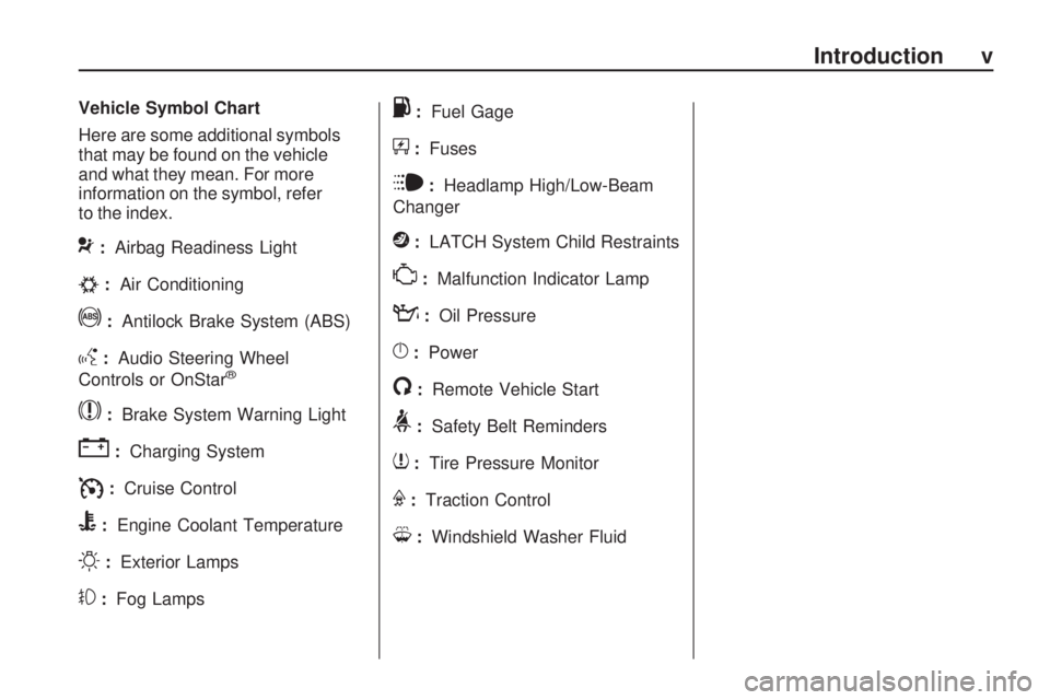
Vehicle Symbol Chart
Here are some additional symbols
that may be found on the vehicle
and what they mean. For more
information on the symbol, refer
to the index.
9:Airbag Readiness Light
#:Air Conditioning
!:Antilock Brake System (ABS)
g:Audio Steering Wheel
Controls or OnStar®
$: Brake System Warning Light
":Charging System
I:Cruise Control
B:Engine Coolant Temperature
O:Exterior Lamps
#:Fog Lamps
.:Fuel Gage
+:Fuses
i:Headlamp High/Low-Beam
Changer
j: LATCH System Child Restraints
*:Malfunction Indicator Lamp
::Oil Pressure
}:Power
/:Remote Vehicle Start
>:Safety Belt Reminders
7:Tire Pressure Monitor
F:Traction Control
M:Windshield Washer Fluid
Introduction v
Page 83 of 318

Instruments and
Controls
Instrument Panel OverviewInstrument Panel Overview.....4-2
ControlsSteering Wheel Adjustment.....4-4
Steering Wheel Controls .........4-4
Horn ...................................
.4-5
Windshield Wiper/Washer .......4-5
Rear Window Wiper/Washer . . . .4-6
Power Outlets (Accessory Power Outlets) ....................
.4-6
Power Outlets (115 Volt Alternating Current) .............
.4-7
Cigarette Lighter ..................
.4-8
Ashtrays .............................
.4-8
Warning Lights, Gages, and
Indicators
Warning Lights, Gages, and
Indicators ..........................
.4-8
Instrument Cluster ................
.4-9
Speedometer .....................
.4-10
Odometer ..........................
.4-10
Trip Odometer ....................
.4-10
Tachometer .......................
.4-10
Fuel Gage .........................
.4-10
Engine Coolant Temperature Gage .............4-11
Safety Belt Reminders ..........4-11
Airbag Readiness Light .........4-12
Passenger Airbag Status Indicator ..........................
.4-13
Charging System Light .........4-14
Malfunction Indicator Lamp .................
.4-14
Brake System Warning Light ...............................
.4-17
Antilock Brake System (ABS) Warning Light ...........4-17
Service All-Wheel Drive Light ...............................
.4-18Speed Sensitive Power
Steering (SSPS) Warning
Light ...............................
.4-18
StabiliTrak®Indicator Light . . . .4-18
Traction Control System (TCS) Warning Light ...........4-19
Tire Pressure Light .............
.4-19
Engine Oil Pressure Light .....4-19
Low Fuel Warning Light ........4-20
Security Light .....................
.4-20
High-Beam on Light .............4-20
Fog Lamp Light ..................
.4-20
Lamps on Reminder .............4-20
Taillamp Indicator Light .........4-21
Low Washer Fluid Warning Light ...............................
.4-21
Cruise Control Light .............4-21
Door Ajar Light ...................
.4-21
Vehicle PersonalizationVehicle Personalization .........4-21
OnStar SystemOnStar®System.................
.4-23
Instruments and Controls 4-1
Page 85 of 318
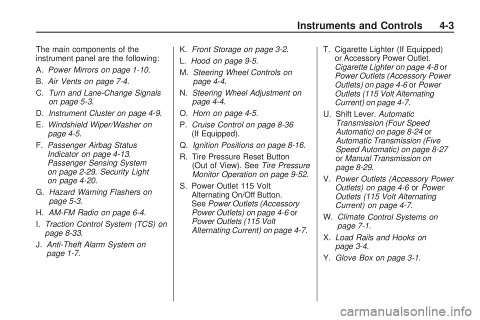
The main components of the
instrument panel are the following:
A.Power Mirrors on page 1-10 .
B. Air Vents on page 7-4.
C. Turn and Lane-Change Signals
on page 5-3.
D. Instrument Cluster on page 4-9 .
E. Windshield Wiper/Washer on
page 4-5.
F. Passenger Airbag Status
Indicator on page 4-13 .
Passenger Sensing System
on page 2-29. Security Light
on page 4-20.
G. Hazard Warning Flashers on
page 5-3.
H. AM-FM Radio on page 6-4 .
I. Traction Control System (TCS) on
page 8-33.
J. Anti-Theft Alarm System on
page 1-7. K.
Front Storage on page 3-2 .
L. Hood on page 9-5.
M. Steering Wheel Controls on
page 4-4.
N. Steering Wheel Adjustment on
page 4-4.
O. Horn on page 4-5.
P. Cruise Control on page 8-36
(If Equipped).
Q. Ignition Positions on page 8-16 .
R. Tire Pressure Reset Button (Out of View). See Tire Pressure
Monitor Operation on page 9-52 .
S. Power Outlet 115 Volt Alternating On/Off Button.
See Power Outlets (Accessory
Power Outlets) on page 4-6 or
Power Outlets (115 Volt
Alternating Current) on page 4-7 .T. Cigarette Lighter (If Equipped)
or Accessory Power Outlet.
Cigarette Lighter on page 4-8 or
Power Outlets (Accessory Power
Outlets) on page 4-6 orPower
Outlets (115 Volt Alternating
Current) on page 4-7.
U. Shift Lever. Automatic
Transmission (Four Speed
Automatic) on page 8-24 or
Automatic Transmission (Five
Speed Automatic) on page 8-27
or Manual Transmission on
page 8-29.
V. Power Outlets (Accessory Power
Outlets) on page 4-6 orPower
Outlets (115 Volt Alternating
Current) on page 4-7 .
W. Climate
Control Systems on
page 7-1.
X. Load Rails and Hooks on
page 3-4.
Y. Glove Box on page 3-1 .
Instruments and Controls 4-3
Page 101 of 318

SeeTraction Control System (TCS)
on page 8-33 for more information.
Contact your dealer/retailer, if
the light does not come on or if it
stays on.
Traction Control System
(TCS) Warning Light
This warning light comes on briefly
when the ignition is turned to
ON/RUN.
It also comes on when the Traction
Control System is turned off by
pressing the TRAC OFF button.
See Traction Control System (TCS)
on page 8-33 for more information. If it stays on or comes on while
driving, there is a problem with the
Traction Control System (TCS),
contact your dealer/retailer.
Tire Pressure Light
This light should come on briefly as
the engine is started.
If there is a tire with low tire
pressure, the light will stay on
or come back on.
See
Tire Pressure Monitor
Operation on page 9-52 for more
information.
Engine Oil Pressure
Light
{CAUTION
Do not keep driving if the oil
pressure is low. The engine can
become so hot that it catches fire.
Someone could be burned. Check
the oil as soon as possible and
have the vehicle serviced.
Notice: Lack of proper engine
oil maintenance can damage
the engine. The repairs would
not be covered by the vehicle
warranty. Always follow the
maintenance schedule in this
manual for changing engine oil.
The oil pressure light should come
on briefly as the engine is started. If it
does not come on have the vehicle
serviced by your dealer/retailer.
Instruments and Controls 4-19
Page 146 of 318
Vehicle Load Limits
It is very important to know how
much weight your vehicle can
carry. Two labels on the vehicle
show how much weight it may
properly carry, the Tire and
Loading Information label and the
Certification label.
{CAUTION
Do not load the vehicle any
heavier than the Gross Vehicle
Weight Rating (GVWR), or
either the maximum front or
rear Gross Axle Weight Rating
(GAWR). If you do, parts on
the vehicle can break, and it
can change the way your
vehicle handles. These could
cause you to lose control and
crash. Also, overloading can
shorten the life of the vehicle. Tire and Loading Information
Label
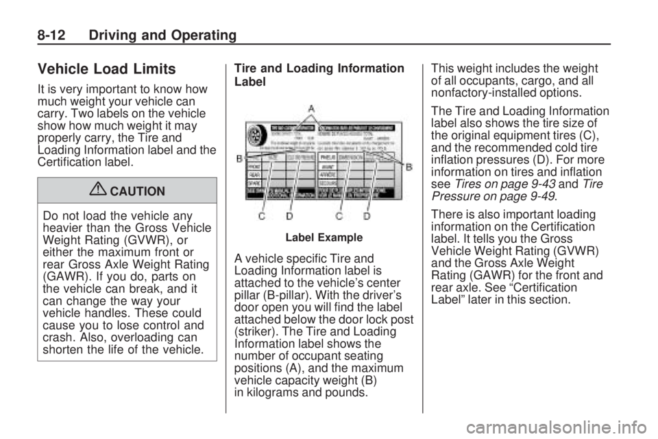
A vehicle specific Tire and
Loading Information label is
attached to the vehicle’s center
pillar (B-pillar). With the driver’s
door open you will find the label
attached below the door lock post
(striker). The Tire and Loading
Information label shows the
number of occupant seating
positions (A), and the maximum
vehicle capacity weight (B)
in kilograms and pounds. This weight includes the weight
of all occupants, cargo, and all
nonfactory-installed options.
The Tire and Loading Information
label also shows the tire size of
the original equipment tires (C),
and the recommended cold tire
inflation pressures (D). For more
information on tires and inflation
see
Tires on page 9-43 andTire
Pressure on page 9-49.
There is also important loading
information on the Certification
label. It tells you the Gross
Vehicle Weight Rating (GVWR)
and the Gross Axle Weight
Rating (GAWR) for the front and
rear axle. See “Certification
Label” later in this section.
Label Example
8-12 Driving and Operating
Page 185 of 318
Vehicle Care
General InformationGeneral Information..............
.9-2
California Proposition 65 Warning ........................
.9-2
California Perchlorate Materials Requirements ........9-3
Accessories and Modifications ......................
.9-3
Vehicle ChecksDoing Your Own
Service Work .....................
.9-4
Hood ..................................
.9-5
Engine Compartment Overview ...........................
.9-6
Engine Oil ...........................
.9-9
Automatic Transmission Fluid ...............................
.9-12
Manual Transmission Fluid . . . .9-14
Hydraulic Clutch .................
.9-15
Engine Air Cleaner/Filter .......9-16
Cooling System ..................
.9-19
Engine Coolant ..................
.9-19Engine Overheating
.............9-23
Power Steering Fluid ............9-24
Washer Fluid .....................
.9-24
Brakes ..............................
.9-26
Brake Fluid ........................
.9-27
Battery ..............................
.9-28
All-Wheel Drive ..................
.9-29
Starter Switch Check ............9-30
Wiper Blade Replacement .....9-30
Headlamp AimingHeadlamp Aiming...............
.9-32
Bulb ReplacementBulb Replacement ..............
.9-33
Halogen Bulbs ...................
.9-33
Headlamps and Parking Lamps .............................
.9-33
Taillamps ...........................
.9-35
License Plate Lamp .............9-36
Replacement Bulbs .............
.9-37
Electrical SystemElectrical System Overload . . . .9-37
Fuses and Circuit Breakers . . .9-38
Engine Compartment Fuse Block ..............................
.9-38
Instrument Panel Fuse Block ..............................
.9-41
Wheels and TiresTires.................................
.9-43
Tire Sidewall Labeling ..........9-44
Tire Designations ................
.9-46
Tire Terminology and Definitions ........................
.9-46
Tire Pressure .....................
.9-49
Tire Pressure Monitor System ............................
.9-50
Tire Pressure Monitor Operation .........................
.9-52
Tire Inspection ...................
.9-54
Tire Rotation ......................
.9-55
When It Is Time for New Tires ...............................
.9-56
Buying New Tires ...............
.9-56
Different Size Tires and Wheels ............................
.9-58
Uniform Tire Quality Grading ...........................
.9-58
Wheel Alignment and Tire Balance ...........................
.9-60
Wheel Replacement .............9-60
Tire Chains ........................
.9-61
If a Tire Goes Flat ..............
.9-62
Tire Changing ....................
.9-63
Compact Spare Tire .............9-68
Vehicle Care 9-1
Page 226 of 318
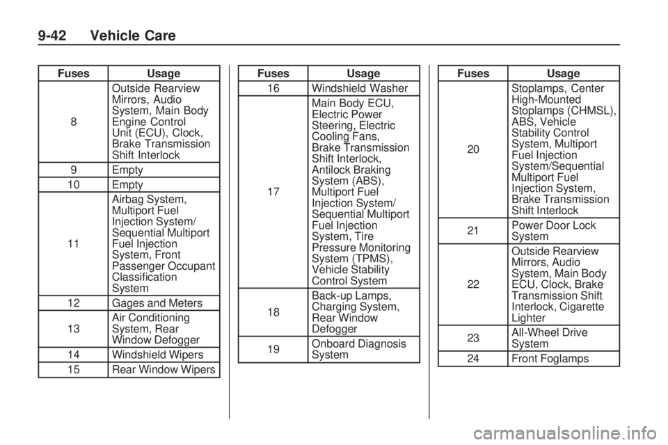
FusesUsage
8 Outside Rearview
Mirrors, Audio
System, Main Body
Engine Control
Unit (ECU), Clock,
Brake Transmission
Shift Interlock
9 Empty
10 Empty
11 Airbag System,
Multiport Fuel
Injection System/
Sequential Multiport
Fuel Injection
System, Front
Passenger Occupant
Classification
System
12 Gages and Meters
13 Air Conditioning
System, Rear
Window Defogger
14 Windshield Wipers
15 Rear Window WipersFuses Usage
16 Windshield Washer
17 Main Body ECU,
Electric Power
Steering, Electric
Cooling Fans,
Brake Transmission
Shift Interlock,
Antilock Braking
System (ABS),
Multiport Fuel
Injection System/
Sequential Multiport
Fuel Injection
System, Tire
Pressure Monitoring
System (TPMS),
Vehicle Stability
Control System
18 Back-up Lamps,
Charging System,
Rear Window
Defogger
19 Onboard Diagnosis
SystemFuses
Usage
20 Stoplamps, Center
High-Mounted
Stoplamps (CHMSL),
ABS, Vehicle
Stability Control
System, Multiport
Fuel Injection
System/Sequential
Multiport Fuel
Injection System,
Brake Transmission
Shift Interlock
21 Power Door Lock
System
22 Outside Rearview
Mirrors, Audio
System, Main Body
ECU, Clock, Brake
Transmission Shift
Interlock, Cigarette
Lighter
23 All-Wheel Drive
System
24 Front Foglamps
9-42 Vehicle Care
Page 227 of 318
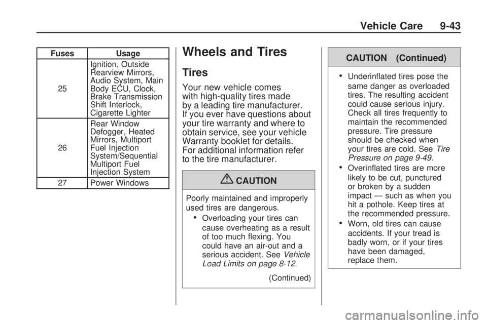
FusesUsage
25 Ignition, Outside
Rearview Mirrors,
Audio System, Main
Body ECU, Clock,
Brake Transmission
Shift Interlock,
Cigarette Lighter
26 Rear Window
Defogger, Heated
Mirrors, Multiport
Fuel Injection
System/Sequential
Multiport Fuel
Injection System
27 Power WindowsWheels and Tires
Tires
Your new vehicle comes
with high-quality tires made
by a leading tire manufacturer.
If you ever have questions about
your tire warranty and where to
obtain service, see your vehicle
Warranty booklet for details.
For additional information refer
to the tire manufacturer.
{CAUTION
Poorly maintained and improperly
used tires are dangerous.
•Overloading your tires can
cause overheating as a result
of too much flexing. You
could have an air-out and a
serious accident. See Vehicle
Load Limits on page 8-12 .
(Continued)
CAUTION (Continued)
•Underinflated tires pose the
same danger as overloaded
tires. The resulting accident
could cause serious injury.
Check all tires frequently to
maintain the recommended
pressure. Tire pressure
should be checked when
your tires are cold. See Tire
Pressure on page 9-49 .
•Overinflated tires are more
likely to be cut, punctured
or broken by a sudden
impact — such as when you
hit a pothole. Keep tires at
the recommended pressure.
•Worn, old tires can cause
accidents. If your tread is
badly worn, or if your tires
have been damaged,
replace them.
Vehicle Care 9-43
Page 228 of 318
Tire Sidewall Labeling
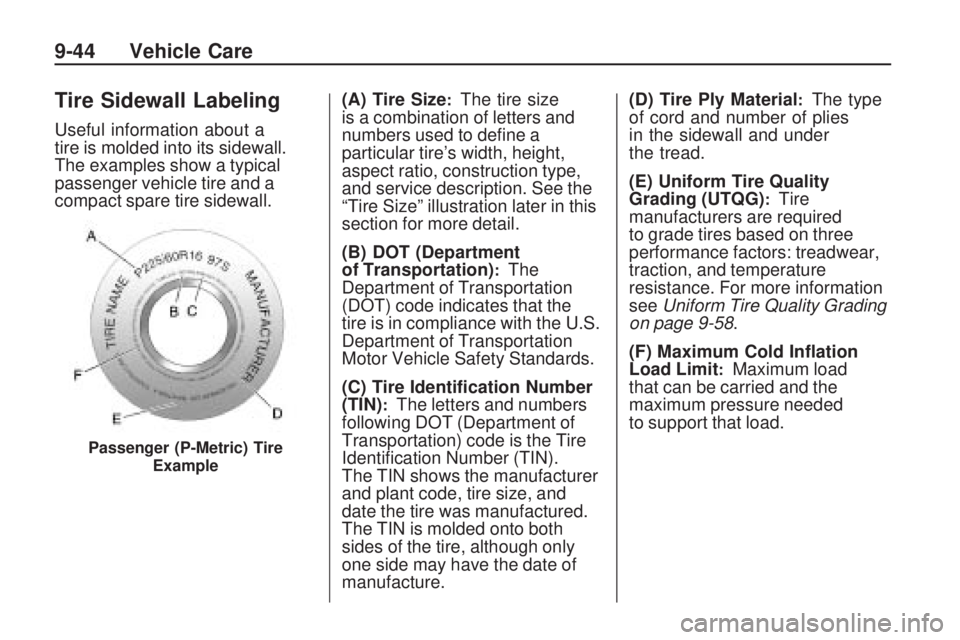
Useful information about a
tire is molded into its sidewall.
The examples show a typical
passenger vehicle tire and a
compact spare tire sidewall.(A) Tire Size
:The tire size
is a combination of letters and
numbers used to define a
particular tire’s width, height,
aspect ratio, construction type,
and service description. See the
“Tire Size” illustration later in this
section for more detail.
(B) DOT (Department
of Transportation)
:The
Department of Transportation
(DOT) code indicates that the
tire is in compliance with the U.S.
Department of Transportation
Motor Vehicle Safety Standards.
(C) Tire Identi�cation Number
(TIN)
:The letters and numbers
following DOT (Department of
Transportation) code is the Tire
Identification Number (TIN).
The TIN shows the manufacturer
and plant code, tire size, and
date the tire was manufactured.
The TIN is molded onto both
sides of the tire, although only
one side may have the date of
manufacture. (D) Tire Ply Material
:The type
of cord and number of plies
in the sidewall and under
the tread.
(E) Uniform Tire Quality
Grading (UTQG)
:Tire
manufacturers are required
to grade tires based on three
performance factors: treadwear,
traction, and temperature
resistance. For more information
see Uniform Tire Quality Grading
on page 9-58.
(F) Maximum Cold In�ation
Load Limit
:Maximum load
that can be carried and the
maximum pressure needed
to support that load.
Passenger (P-Metric) Tire
Example
9-44 Vehicle Care
Page 229 of 318
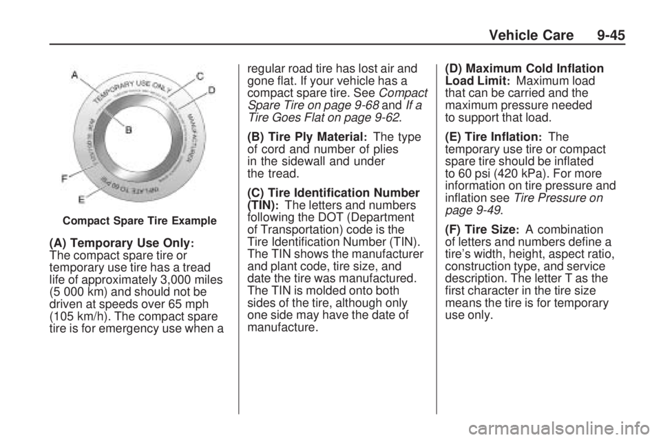
(A) Temporary Use Only:The compact spare tire or
temporary use tire has a tread
life of approximately 3,000 miles
(5 000 km) and should not be
driven at speeds over 65 mph
(105 km/h). The compact spare
tire is for emergency use when aregular road tire has lost air and
gone flat. If your vehicle has a
compact spare tire. See
Compact
Spare Tire on page 9-68 andIf a
Tire Goes Flat on page 9-62 .
(B) Tire Ply Material
:The type
of cord and number of plies
in the sidewall and under
the tread.
(C) Tire Identi�cation Number
(TIN)
:The letters and numbers
following the DOT (Department
of Transportation) code is the
Tire Identification Number (TIN).
The TIN shows the manufacturer
and plant code, tire size, and
date the tire was manufactured.
The TIN is molded onto both
sides of the tire, although only
one side may have the date of
manufacture. (D) Maximum Cold In�ation
Load Limit
:Maximum load
that can be carried and the
maximum pressure needed
to support that load.
(E) Tire In�ation
:The
temporary use tire or compact
spare tire should be inflated
to 60 psi (420 kPa). For more
information on tire pressure and
inflation see Tire Pressure on
page 9-49.
(F) Tire Size
:A combination
of letters and numbers define a
tire’s width, height, aspect ratio,
construction type, and service
description. The letter T as the
first character in the tire size
means the tire is for temporary
use only.Compact Spare Tire Example
Vehicle Care 9-45