40 amp Ram 1500 2014 Repair Manual
[x] Cancel search | Manufacturer: RAM, Model Year: 2014, Model line: 1500, Model: Ram 1500 2014Pages: 806, PDF Size: 5.78 MB
Page 555 of 806
Example: If garage temperature = 68°F (20°C) and the
outside temperature = 32°F (0°C) then the cold tire
inflation pressure should be increased by 3 psi (21 kPa),
which equals 1 psi (7 kPa) for every 12°F (7°C) for this
outside temperature condition.
Tire pressure may increase from 2 to 6 psi (13 to 40 kPa)
during operation. DO NOT reduce this normal pressure
build up or your tire pressure will be too low.
Tire Pressures For High Speed Operation
The manufacturer advocates driving at safe speeds and
within posted speed limits. Where speed limits or condi-
tions are such that the vehicle can be driven at high
speeds, maintaining correct tire inflation pressure is very
important. Increased tire pressure and reduced vehicle
loading may be required for high-speed vehicle opera-
tion. Refer to your authorized tire dealer or original
equipment vehicle dealer for recommended safe operat-
ing speeds, loading and cold tire inflation pressures.
WARNING!
High speed driving with your vehicle under maxi-
mum load is dangerous. The added strain on your
tires could cause them to fail. You could have a
serious collision. Do not drive a vehicle loaded to the
maximum capacity at continuous speeds above
75 mph (120 km/h).
Radial Ply Tires
WARNING!
Combining radial ply tires with other types of tires
on your vehicle will cause your vehicle to handle
poorly. The instability could cause a collision. Al-
ways use radial ply tires in sets of four. Never
combine them with other types of tires.
5
STARTING AND OPERATING 553
Page 558 of 806
See the tire pressure monitoring section for more infor-
mation.
Spare Tires — If Equipped
NOTE:For vehicles equipped with TIREFIT instead of a
spare tire, please refer to “TIREFIT KIT” in “What To Do
In Emergencies” for further information.
CAUTION!
Because of the reduced ground clearance, do not take
your vehicle through an automatic car wash with a
compact, full size or limited-use temporary spare
installed. Damage to the vehicle may result.
Spare Tire Matching Original Equipped Tire And
Wheel — If Equipped
Your vehicle may be equipped with a spare tire and
wheel equivalent in look and function to the original
equipment tire and wheel found on the front or rear axle
of your vehicle. This spare tire may be used in the tire
rotation for your vehicle. If your vehicle has this option,
refer to an authorized tire dealer for the recommended
tire rotation pattern.
Compact Spare Tire — If Equipped
The compact spare is for temporary emergency use only.
You can identify if your vehicle is equipped with a
compact spare by looking at the spare tire description on
the Tire and Loading Information Placard located on the
driver ’s side door opening or on the sidewall of the tire.
Compact spare tire descriptions begin with the letter “T”
or “S” preceding the size designation. Example: T145/
80D18 103M.
T, S = Temporary Spare Tire
556 STARTING AND OPERATING
Page 562 of 806
WARNING!
Tires and the spare tire should be replaced after six
years, regardless of the remaining tread. Failure to
follow this warning can result in sudden tire failure.
You could lose control and have a collision resulting
in serious injury or death.
Keep dismounted tires in a cool, dry place with as little
exposure to light as possible. Protect tires from contact
with oil, grease, and gasoline.
Replacement Tires
The tires on your new vehicle provide a balance of many
characteristics. They should be inspected regularly for
wear and correct cold tire inflation pressure. The manu-
facturer strongly recommends that you use tires equiva-
lent to the originals in size, quality and performance
when replacement is needed. Refer to the paragraph on
“Tread Wear Indicator.” Refer to the Tire and Loading Information placard or the Vehicle Certification Label for
the size designation of your tire. The Load Index and
Speed Symbol for your tire will be found on the original
equipment tire sidewall. See the Tire Sizing Chart ex-
ample found in the Tire Safety Information section of this
manual for more information relating to the Load Index
and Speed Symbol of a tire.
It is recommended to replace the two front tires or two
rear tires as a pair. Replacing just one tire can seriously
affect your vehicle’s handling. If you ever replace a
wheel, make sure that the wheel’s specifications match
those of the original wheels.
It is recommended you contact your authorized tire
dealer or original equipment dealer with any questions
you may have on tire specifications or capability. Failure
to use equivalent replacement tires may adversely affect
the safety, handling, and ride of your vehicle.
560 STARTING AND OPERATING
Page 568 of 806
NOTE:If your vehicle is equipped with a Tire Pressure
Information System (TPIS):
• The Tire Pressure Information System (TPIS) uses
unique sensors in the inner rear wheels to help identify
them from the outer rear wheels, because of this, the
inner and outer wheel locations can’t be switched.
• After a tire rotation is completed, as shown below, the
system can auto learn the locations of each sensor ID.
Auto learning/localization occurs when the vehicle
ignition status is changed from Off to On and speeds of
greater than 5 mph (8km/h) are obtained and remain
over 5mph (8km/h) for at about a 15 minute period.
You may need to drive for 20 minutes to account
slower speeds and stops.
• If the tires are rotated incorrectly, The Auto localization
of the TPIS sensors will fail to locate correctly resulting
in incorrect locations for the pressure values displayed
in the Instrument Cluster.CAUTION!
3500 Dual Rear Tires may only have one approved
direction of rotation. This is to accommodate the
asymmetrical design (tread pattern) of the On/Off-
Road tire and the use of Outline White Letter (OWL)
tires.
• When replacing a flat, the spare tire may have to be
remounted on the rim, or installed at a different
location, to maintain the correct placement of the
tire on the wheel relative to the tire/wheel position
on the truck. For example, if the spare is used to
replace an outer rear tire it will have to be re-
mounted on the rim so that the wheel is dished
inward. That way the tread design of asymmetrical
tires and the white writing of the OWL tires will
maintain proper position.
566 STARTING AND OPERATING
Page 570 of 806
to be driven for up to 20 minutes above 15 mph
(25 km/h) in order for the TPMS to receive this informa-
tion.
For example, your vehicle may have a recommended
cold (parked for more than three hours) placard pressure
of 30 psi (207 kPa). If the ambient temperature is 68°F
(20°C) and the measured tire pressure is 27 psi (186 kPa),
a temperature drop to 20°F (-7°C) will decrease the tire
pressure to approximately 23 psi (158 kPa). This tire
pressure is sufficiently low enough to turn ON the “Tire
Pressure Monitoring Telltale Light.” Driving the vehicle
may cause the tire pressure to rise to approximately 27
psi (186 kPa), but the “Tire Pressure Monitoring Telltale
Light” will still be ON. In this situation, the “Tire
Pressure Monitoring Telltale Light” will turn OFF only
after the tires are inflated to the vehicle’s recommended
cold placard pressure value.CAUTION!
•The TPMS has been optimized for the original
equipment tires and wheels. TPMS pressures and
warning have been established for the tire size
equipped on your vehicle. Undesirable system op-
eration or sensor damage may result when using
replacement equipment that is not of the same size,
type, and/or style. Aftermarket wheels can cause
sensor damage. Using aftermarket tire sealants may
cause the Tire Pressure Monitoring System (TPMS)
sensor to become inoperable. After using an after-
market tire sealant it is recommended that you take
your vehicle to your local dealer to have your
sensor function checked.
• After inspecting or adjusting the tire pressure,
always reinstall the valve stem cap. This will
prevent moisture and dirt from entering the valve
stem, which could damage the TPM sensor.
568 STARTING AND OPERATING
Page 583 of 806
Fuel System Cautions
CAUTION!
Follow these guidelines to maintain your vehicle’s
performance:
•The use of leaded gas is prohibited by Federal law.
Using leaded gasoline can impair engine perfor-
mance and damage the emissions control system.
• An out-of-tune engine or certain fuel or ignition
malfunctions can cause the catalytic converter to
overheat. If you notice a pungent burning odor or
some light smoke, your engine may be out of tune
or malfunctioning and may require immediate ser-
vice. Contact your authorized dealer for service
assistance.
(Continued)
CAUTION! (Continued)
•The use of fuel additives, which are now being
sold as octane enhancers, is not recommended.
Most of these products contain high concentrations
of methanol. Fuel system damage or vehicle perfor-
mance problems resulting from the use of such
fuels or additives is not the responsibility of the
manufacturer.
NOTE: Intentional tampering with the emissions control
system can result in civil penalties being assessed against
you.
5
STARTING AND OPERATING 581
Page 595 of 806
Trailer Sway Control
The trailer sway control can be a mechanical telescoping
link that can be installed between the hitch receiver and
the trailer tongue that typically provides adjustable fric-
tion associated with the telescoping motion to dampen
any unwanted trailer swaying motions while traveling.
If equipped, the electronic Trailer Sway Control (TSC)
recognizes a swaying trailer and automatically applies
individual wheel brakes and/or reduces engine power to
attempt to eliminate the trailer sway.
Weight-Carrying Hitch
A weight-carrying hitch supports the trailer tongue
weight, just as if it were luggage located at a hitch ball or
some other connecting point of the vehicle. These kinds
of hitches are the most popular on the market today and
they are commonly used to tow small and medium sized
trailers.
Weight-Distributing Hitch
A weight-distributing system works by applying lever-
age through spring (load) bars. They are typically used
for heavier loads to distribute trailer tongue weight to the
tow vehicle’s front axle and the trailer axle(s). When used
in accordance with the manufacturer’s directions, it pro-
vides for a more level ride, offering more consistent
steering and brake control thereby enhancing towing
safety. The addition of a friction/hydraulic sway control
also dampens sway caused by traffic and crosswinds and
contributes positively to tow vehicle and trailer stability.
Trailer sway control and a weight distributing (load
equalizing) hitch are recommended for heavier Tongue
Weights (TW) and may be required depending on vehicle
and trailer configuration/loading to comply with Gross
Axle Weight Rating (GAWR) requirements. Weight Dis-
tribution hitched are recommended for loads in excess of
5,000 lbs (2,268 kg).
5
STARTING AND OPERATING 593
Page 601 of 806
Trailer And Tongue Weight
Always load a trailer with 60% of the weight in the front
of the trailer. This places 10% of the GTW on the tow
hitch of your vehicle. Loads balanced over the wheels or
heavier in the rear can cause the trailer to swayseverely
side to side which will cause loss of control of the vehicle
and trailer. Failure to load trailers heavier in front is the
cause of many trailer collisions. Never exceed the maxi-
mum tongue weight stamped on your trailer hitch.
Consider the following items when computing the
weight on the rear axle of the vehicle:
•The tongue weight of the trailer
• The weight of any other type of cargo or equipment
put in or on your vehicle
• The weight of the driver and all passengers
5
STARTING AND OPERATING 599
Page 607 of 806
The user interface consists of the following:
Manual Brake Control Lever
Slide the manual brake control lever to the right to
activate power to the trailer’s electric brakes independent
of the tow vehicle’s brakes. If the manual brake control
lever is activated while the brake is also applied, the
greater of the two inputs determines the power sent to
the trailer brakes.
The trailer and the vehicle’s brake lamps will come on
when either vehicle braking or manual trailer brakes are
applied.
Trailer Brake Status Indicator Light
This light indicates the trailer electrical connection status.
If no electrical connection is detected after the ignition is
turned on, pressing the GAIN adjustment button orsliding the manual brake control lever will display the
GAIN setting for 10 seconds and the “Trailer Brake Status
Indicator Light” will not be displayed.
If a fault is detected in the trailer wiring or the Integrated
Trailer Brake Module (ITBM), the “Trailer Brake Status
Indicator Light” will flash.
GAIN Adjustment Buttons (+/-)
Pressing these buttons will adjust the brake control
power output to the trailer brakes in 0.5 increments. The
GAIN setting can be increased to a maximum of 10 or
decreased to a minimum of 0 (no trailer braking).
GAIN
The GAIN setting is used to set the trailer brake control
for the specific towing condition and should be changed
as towing conditions change. Changes to towing condi-
tions include trailer load, vehicle load, road conditions
and weather.
5
STARTING AND OPERATING 605
Page 612 of 806
Towing Tips
Before setting out on a trip, practice turning, stopping
and backing the trailer up in an area away from heavy
traffic.
Automatic Transmission
The “DRIVE” range can be selected when towing. The
transmission controls include a drive strategy to avoid
frequent shifting when towing. However, if frequent
shifting does occur while in DRIVE, select “TOW/
HAUL” mode or select a lower gear range (using the
Electronic Range Select (ERS) switches).
NOTE:Using “TOW/HAUL” mode or selecting a lower
gear range (using the ERS switches) while operating the
vehicle under heavy loading conditions will improve
performance and extend transmission life by reducing
excessive shifting and heat build up. This action will also
provide better engine braking.
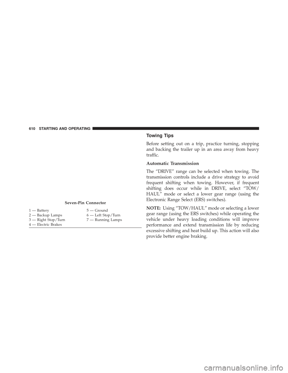
Seven-Pin Connector
1 — Battery 5 — Ground
2 — Backup Lamps 6 — Left Stop/Turn
3 — Right Stop/Turn 7 — Running Lamps
4 — Electric Brakes 610 STARTING AND OPERATING