display Ram 1500 2015 Service Manual
[x] Cancel search | Manufacturer: RAM, Model Year: 2015, Model line: 1500, Model: Ram 1500 2015Pages: 871, PDF Size: 24.83 MB
Page 222 of 871

Canadian/Gate Operator Programming
For programming transmitters in Canada/United States
that require the transmitter signals to “time-out” after
several seconds of transmission.
Canadian radio frequency laws require transmitter sig-
nals to time-out (or quit) after several seconds of trans-
mission – which may not be long enough for HomeLink®
to pick up the signal during programming. Similar to this
Canadian law, some U.S. gate operators are designed to
time-out in the same manner.
It may be helpful to unplug the device during the cycling
process to prevent possible overheating of the garage
door or gate motor.
1. Turn the ignition switch to the ON/RUN position.
For vehicle’s equipped with Keyless Enter-N-Go™, place
the ignition in the RUN position with the Engine ON.
2. Place the hand - held transmitter 1 to 3 inches (3 to 8
cm) away from the HomeLink® button you wish to
program.
3. Push and hold the Homelink® button while you push
and release (“cycle”), your hand - held transmitter
every two seconds.
4. Continue to hold both buttons until the EVIC/DID
display changes from “CHANNEL # TRAINING” to
“CHANNEL # TRAINED,” then release both buttons.
NOTE:
•It may take up to 30 seconds or longer in some cases
for the channel to train.
•If the EVIC/DID displays “DID NOT TRAIN” repeat
from Step 2.
220 UNDERSTANDING THE FEATURES OF YOUR VEHICLE
Page 223 of 871

5. Push and hold the programmed HomeLink® button.
The EVIC/DID will display “CHANNEL # TRANS-
MIT.” If the device is plugged in and activates, pro-
gramming is complete.
If you unplugged the garage door opener/device for
programming, plug it back in at this time.
Reprogramming A Single HomeLink® Button
(Canadian/Gate Operator)
To reprogram a channel that has been previously trained,
follow these steps:
1. Turn the ignition switch to the ON/RUN position.
For vehicle’s equipped with Keyless Enter-N-Go™, place
the ignition in the RUN position with the Engine ON.
2. Push and hold the desired HomeLink® button until
the EVIC/DID displays “CHANNEL # TRAINING”
Do not release the button.
3.Without releasing the buttonproceed with
“Canadian/Gate Operator Programming” Step 2 and
follow all remaining steps.
Using HomeLink®
To operate, push and release the programmed
HomeLink® button. Activation will now occur for the
programmed device (i.e., garage door opener, gate opera-
tor, security system, entry door lock, home/office light-
ing, etc.,). The hand-held transmitter of the device may
also be used at any time.
Security
It is advised to erase all channels before you sell or turn
in your vehicle.
To erase the channels press and hold the two outside
HomeLink® buttons (I and III) for up 20 seconds. The
Electronic Vehicle Information Center (EVIC) or Driver
3
UNDERSTANDING THE FEATURES OF YOUR VEHICLE 221
Page 224 of 871
Interactive Display (DID) will display “CLEARING
CHANNELS.” Release the buttons when the EVIC/DID
displays “CHANNELS CLEARED.”
The HomeLink® Universal Transceiver is disabled when
the Vehicle Security Alarm is active.
Troubleshooting Tips
If you are having trouble programming HomeLink®,
here are some of the most common solutions:
•Replace the battery in the original hand-held transmitter.
•Push the LEARN button on the Garage Door Opener
to complete the training for a Rolling Code.
•Did you unplug the device for programming and
remember to plug it back in?
If you have any problems, or require assistance, please
call toll-free 1-800-355-3515 or, on the Internet at
HomeLink.com for information or assistance.
WARNING!
Vehicle exhaust contains carbon monoxide, a danger-
ous gas. Do not run your vehicle in the garage while
programming the transceiver. Exhaust gas can cause
serious injury or death.
WARNING!
Your motorized door or gate will open and close
while you are programming the universal trans-
ceiver. Do not program the transceiver if people, pets
or other objects are in the path of the door or gate.
Only use this transceiver with a garage door opener
that has a “stop and reverse” feature as required by
Federal safety standards. This includes most garage
door opener models manufactured after 1982. Do not
(Continued)
222 UNDERSTANDING THE FEATURES OF YOUR VEHICLE
Page 255 of 871
There are stampings in the sheet metal on the inner side
bulkheads of the box in front of and behind both wheel
housings. Place wooden boards across the box from side
to side to create separate load compartments in the
pickup box.
There are four tie-down cleats bolted to the lower sides of
the pickup box that can sustain loads up to 1000 lbs
(450 kg) total.
Cargo Camera — If Equipped
Your vehicle may be equipped with the Cargo Camera
that allows you to see an image of the inside of the
pickup box. The image will be displayed in the
Uconnect® screen.
A display timer is initiated when the cargo camera image
is displayed. The image will continue to be displayed
until the display timer exceeds 10 seconds and the vehicle
speed is above 8 mph (13 km/h) or the image is deacti-
vated by touching the Uconnect® display.
NOTE:If the vehicle speed remains below 8 mph
(13 km/h), the cargo camera image will be displayed
continuously until deactivated by touching the
Uconnect® display.
The Cargo Camera is located in the bottom center area of
the center high-mounted stoplamp (CHMSL).
NOTE:If snow, ice, mud, or any foreign substance builds
up on the camera lens, clean the lens, rinse with water,
and dry with a soft cloth. Do not cover the lens.
Turning Cargo Camera On Or Off — With
Uconnect® 8.4A/8.4AN
1. Press the “Controls” button located on the bottom of
the Uconnect® display.
2. Press the “Cargo Camera” buttonto turn the
Cargo Camera system ON.
3
UNDERSTANDING THE FEATURES OF YOUR VEHICLE 253
Page 256 of 871
NOTE:The Cargo Camera image may be deactivated by
pressing the Uconnect® display. The previous selected
screen will appear.
RAMBOX® — IF EQUIPPED
The RamBox® system is an integrated pickup box stor-
age and cargo management system consisting of three
features:
•Integrated box side storage bins
•Cargo extender/divider
•Bed rail tie-down system
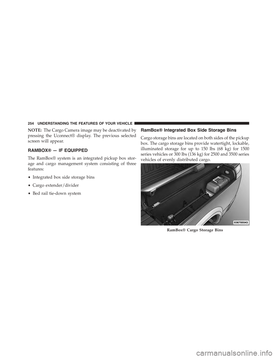
RamBox® Integrated Box Side Storage Bins
Cargo storage bins are located on both sides of the pickup
box. The cargo storage bins provide watertight, lockable,
illuminated storage for up to 150 lbs (68 kg) for 1500
series vehicles or 300 lbs (136 kg) for 2500 and 3500 series
vehicles of evenly distributed cargo.
RamBox® Cargo Storage Bins
254 UNDERSTANDING THE FEATURES OF YOUR VEHICLE
Page 285 of 871
UNDERSTANDING YOUR INSTRUMENT PANEL
CONTENTS
!INSTRUMENT PANEL FEATURES..........286
!INSTRUMENT CLUSTER — MIDLINE (EVIC) . .287
!INSTRUMENT CLUSTER — PREMIUM (DID) . .288
!INSTRUMENT CLUSTER DESCRIPTIONS.....289
!ELECTRONIC VEHICLE INFORMATION
CENTER (EVIC).......................302
▫Electronic Vehicle Information Center (EVIC)
Displays — 3.5” Display................304
▫Oil Life Reset........................306
▫EVIC Messages.......................307
▫EVIC Red Telltales.....................312
▫EVIC Yellow Telltales...................314
▫EVIC White Telltales...................316
▫EVIC Selectable Menu Items.............317
!DRIVER INFORMATION DISPLAY (DID).....331
▫Driver Information Display (DID) Displays . . .333
▫Oil Life Reset........................335
▫DID Messages........................336
▫DID Red Telltales......................341
▫DID Yellow Telltales....................343
4
Page 289 of 871

INSTRUMENT CLUSTER — MIDLINE (EVIC)
Electronic Vehicle Information Display (EVIC)
4
UNDERSTANDING YOUR INSTRUMENT PANEL 287
Page 290 of 871

INSTRUMENT CLUSTER — PREMIUM (DID)
Driver Information Display (DID)
288 UNDERSTANDING YOUR INSTRUMENT PANEL
Page 298 of 871
CAUTION!
The TPMS has been optimized for the original
equipment tires and wheels. TPMS pressures and
warning have been established for the tire size
equipped on your vehicle. Undesirable system opera-
tion or sensor damage may result when using re-
placement equipment that is not of the same size,
type, and/or style. Aftermarket wheels can cause
sensor damage. Do not use tire sealant from a can or
balance beads if your vehicle is equipped with a
TPMS, as damage to the sensors may result.
NOTE:The TPMS telltale is also accompanied by a “Low
Tire” message in the odometer (Base Cluster), or in the
Electronic Vehicle Information Center (EVIC) screen in-
dicating “Low Tire” for EVIC enabled clusters.
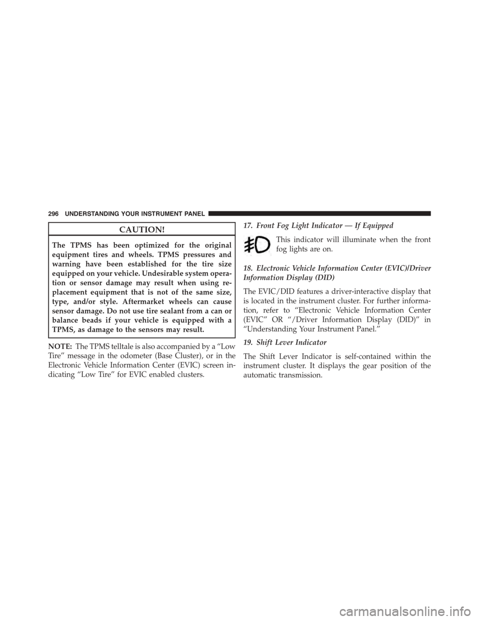
17. Front Fog Light Indicator — If Equipped
This indicator will illuminate when the front
fog lights are on.
18. Electronic Vehicle Information Center (EVIC)/Driver
Information Display (DID)
The EVIC/DID features a driver-interactive display that
is located in the instrument cluster. For further informa-
tion, refer to “Electronic Vehicle Information Center
(EVIC” OR “/Driver Information Display (DID)” in
“Understanding Your Instrument Panel.”
19. Shift Lever Indicator
The Shift Lever Indicator is self-contained within the
instrument cluster. It displays the gear position of the
automatic transmission.
296 UNDERSTANDING YOUR INSTRUMENT PANEL
Page 299 of 871
NOTE:The highest available transmission gear is dis-
played in the lower right corner of the EVIC/DID
whenever the Electronic Range Select (ERS) feature is
active. Use the +/- selector on the shift lever to activate
ERS. Refer to “Automatic Transmission” in “Starting And
Operating” for further information.
20. Driver Information Display (DID) Menu
The Driver Information Display (DID) features a driver-
interactive display that is located in the instrument
cluster. For further information, refer to “Driver Informa-
tion Display (DID)” in “Understanding Your Instrument
Panel.”
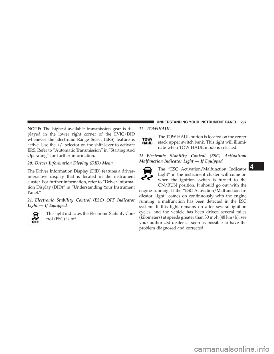
21. Electronic Stability Control (ESC) OFF Indicator
Light — If Equipped
This light indicates the Electronic Stability Con-
trol (ESC) is off.
22. TOW/HAUL
The TOW HAUL button is located on the center
stack upper switch bank. This light will illumi-
nate when TOW HAUL mode is selected.
23. Electronic Stability Control (ESC) Activation/
Malfunction Indicator Light — If Equipped
The “ESC Activation/Malfunction Indicator
Light” in the instrument cluster will come on
when the ignition switch is turned to the
ON/RUN position. It should go out with the
engine running. If the “ESC Activation/Malfunction In-
dicator Light” comes on continuously with the engine
running, a malfunction has been detected in the ESC
system. If this light remains on after several ignition
cycles, and the vehicle has been driven several miles
(kilometers) at speeds greater than 30 mph (48 km/h), see
your authorized dealer as soon as possible to have the
problem diagnosed and corrected.
4
UNDERSTANDING YOUR INSTRUMENT PANEL 297