Hub Ram 1500 2015 Owner's Manual
[x] Cancel search | Manufacturer: RAM, Model Year: 2015, Model line: 1500, Model: Ram 1500 2015Pages: 871, PDF Size: 24.83 MB
Page 73 of 871
On the other hand, depending on the type and location of
impact, Advanced Front Air Bags may deploy in crashes
with little vehicle front-end damage but that produce a
severe initial deceleration.
Because air bag sensors measure vehicle deceleration
over time, vehicle speed and damage by themselves are
not good indicators of whether or not an air bag should
have deployed.
Seat belts are necessary for your protection in all colli-
sions, and also are needed to help keep you in position,
away from an inflating air bag.
When the ORC detects a collision requiring the Ad-
vanced Front Air Bags, it signals the inflator units. A large
quantity of non-toxic gas is generated to inflate the
Advanced Front Air Bags.
The steering wheel hub trim cover and the upper right
side of the instrument panel separate and fold out of the
way as the air bags inflate to their full size. The Advanced
Front Air Bags fully inflate in less time than it takes to
blink your eyes. The air bags then quickly deflate while
helping to restrain the driver and front passenger.
Knee Impact Bolsters
The Knee Impact Bolsters help protect the knees of the
driver and front passenger, and position the front occu-
pants for improved interaction with the Advanced Front
Air Bags.
WARNING!
•Do not drill, cut, or tamper with the knee impact
bolsters in any way.
•Do not mount any accessories to the knee impact
bolsters such as alarm lights, stereos, citizen band
radios, etc.
2
THINGS TO KNOW BEFORE STARTING YOUR VEHICLE 71
Page 83 of 871
Maintaining Your Air Bag System
WARNING!
•Modifications to any part of the air bag system
could cause it to fail when you need it. You could
be injured if the air bag system is not there to
protect you. Do not modify the components or
wiring, including adding any kind of badges or
stickers to the steering wheel hub trim cover or the
upper right side of the instrument panel. Do not
modify the front bumper, vehicle body structure, or
add aftermarket side steps or running boards.
•It is dangerous to try to repair any part of the air
bag system yourself. Be sure to tell anyone who
works on your vehicle that it has an air bag system.
(Continued)
WARNING!(Continued)
•Do not attempt to modify any part of your air bag
system. The air bag may inflate accidentally or may
not function properly if modifications are made.
Take your vehicle to an authorized dealer for any
air bag system service. If your seat, including your
trim cover and cushion, needs to be serviced in any
way (including removal or loosening/tightening of
seat attachment bolts), take the vehicle to your
authorized dealer. Only manufacturer approved
seat accessories may be used. If it is necessary to
modify the air bag system for persons with dis-
abilities, contact your authorized dealer.
2
THINGS TO KNOW BEFORE STARTING YOUR VEHICLE 81
Page 397 of 871
iPod®/USB/MP3 CONTROL — IF EQUIPPED
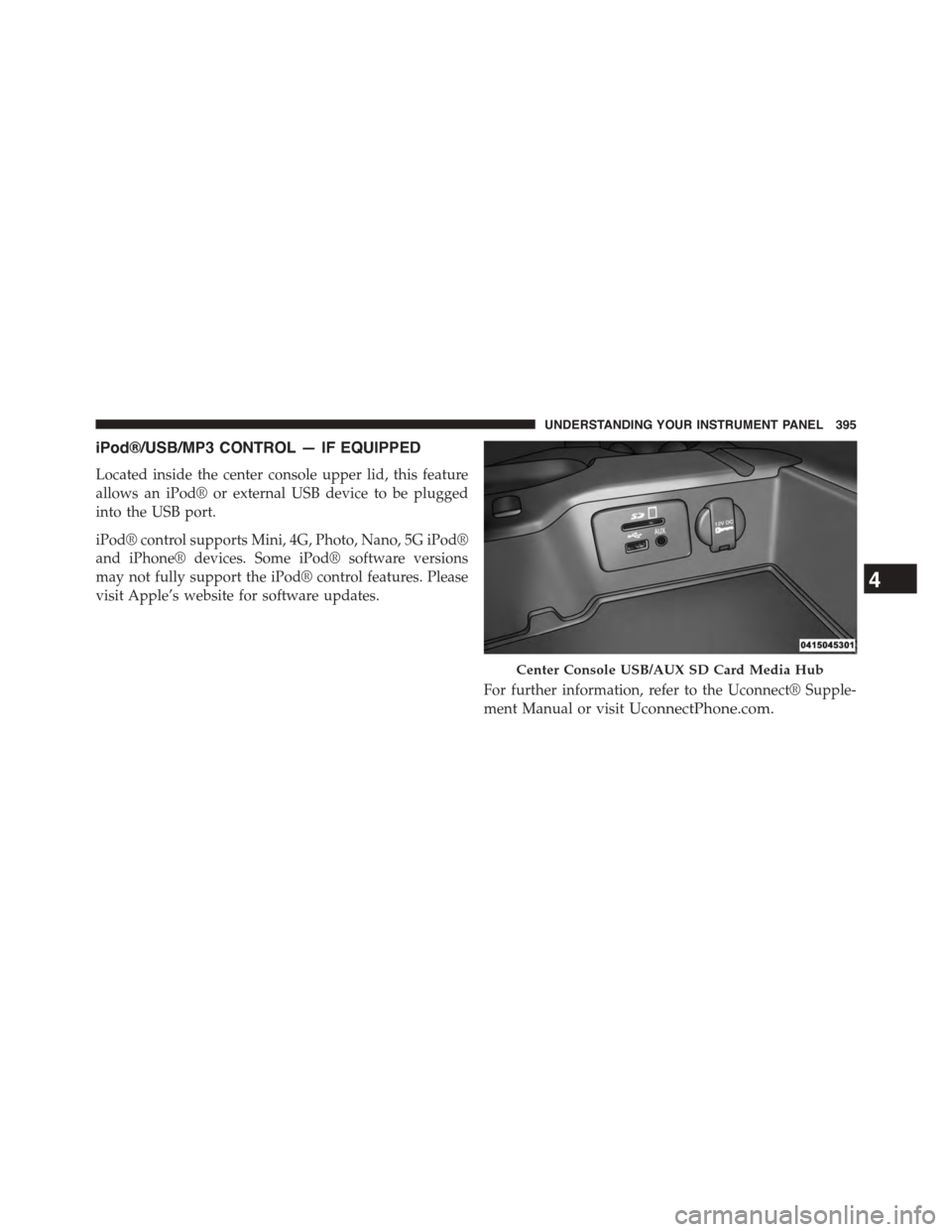
Located inside the center console upper lid, this feature
allows an iPod® or external USB device to be plugged
into the USB port.
iPod® control supports Mini, 4G, Photo, Nano, 5G iPod®
and iPhone® devices. Some iPod® software versions
may not fully support the iPod® control features. Please
visit Apple’s website for software updates.
For further information, refer to the Uconnect® Supple-
ment Manual or visitUconnectPhone.com.
Center Console USB/AUX SD Card Media Hub
4
UNDERSTANDING YOUR INSTRUMENT PANEL 395
Page 720 of 871
1. Remove the spare wheel, jack, and tools from storage.
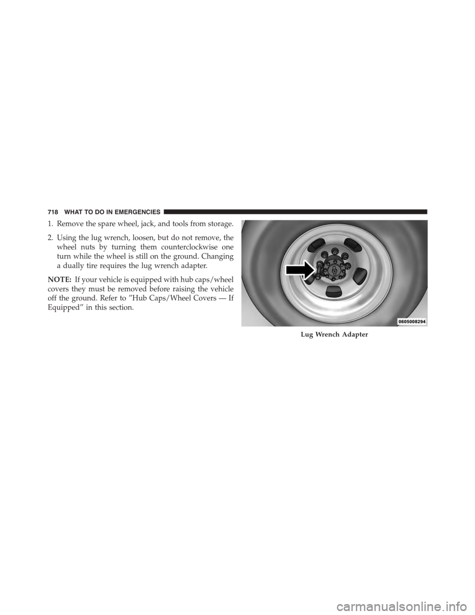
2. Using the lug wrench, loosen, but do not remove, the
wheel nuts by turning them counterclockwise one
turn while the wheel is still on the ground. Changing
a dually tire requires the lug wrench adapter.
NOTE:If your vehicle is equipped with hub caps/wheel
covers they must be removed before raising the vehicle
off the ground. Refer to ”Hub Caps/Wheel Covers — If
Equipped” in this section.
Lug Wrench Adapter
718 WHAT TO DO IN EMERGENCIES
Page 729 of 871
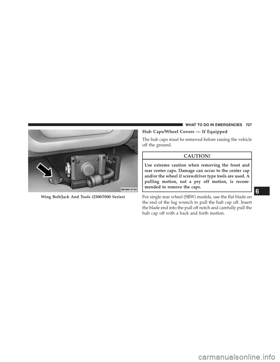
Hub Caps/Wheel Covers — If Equipped
The hub caps must be removed before raising the vehicle
off the ground.
CAUTION!
Use extreme caution when removing the front and
rear center caps. Damage can occur to the center cap
and/or the wheel if screwdriver type tools are used. A
pulling motion, not a pry off motion, is recom-
mended to remove the caps.
For single rear wheel (SRW) models, use the flat blade on
the end of the lug wrench to pull the hub cap off. Insert
the blade end into the pull off notch and carefully pull the
hub cap off with a back and forth motion.
Wing Bolt/Jack And Tools (2500/3500 Series)6
WHAT TO DO IN EMERGENCIES 727
Page 730 of 871
On 3500 models with dual rear wheels (DRW), you must
first remove the hub caps. The jack handle driver has a
hook at one end that will fit in the pull off notch of the
rear hub caps. Position the hook and pull straight out on
the ratchet firmly. The hub cap should pop off. The wheel
skins can now be removed. For the front hub cap, use the
flat blade on the end of the lug wrench to pull the caps
off. The wheel skin can now be removed.
CAUTION!
•Use a pulling motion to remove the hub cap. Do not
use a twisting motion when removing the hub cap,
damage to the hub cap; finish may occur.
•The rear hub caps on the dual rear wheel has two
pull off notches. Make sure that the hook of the
jack handle driver is located squarely in the cap
notch before attempting to pull off.
You must use the flat end of the lug wrench to pull off the
wheel skins. Locate the hub cap pull notches (2 notches
on each cap). Insert the flat tip completely and using a
back and forth motion, loosen the wheel skin. Repeat this
procedure around the tire until the skin pops off.
Replace the wheel skins first using a rubber mallet. When
replacing the hub caps, tilt the cap retainer over the lug
nut bolt circle and strike the high side down with a
rubber mallet. Be sure that the hub caps and wheel skins
are firmly seated around the wheel.
HOISTING
A conventional floor jack may be used at the jacking
locations. Refer to the graphics that show jacking loca-
tions. However, a floor jack or frame hoist must never be
used on any other parts of the underbody.
728 WHAT TO DO IN EMERGENCIES
Page 857 of 871
Gear Ranges.............................471
Gear Select Lever Override..................736
General Information.......................634
Glass Cleaning...........................794
Grocery Bag Retainer.......................245
Gross Axle Weight Rating...................649
Gross Vehicle Weight Rating..................648
Guide, Body Builders........................6
GVWR.................................646
Hazard
Driving Through Flowing, Rising, or Shallow
Standing Water.........................553
Hazard Warning Flasher....................685
Headlights..............................810
Automatic............................167
Cleaning.............................794
High Beam............................178
High Beam/Low Beam Select Switch.........178
Passing..............................177
Switch...............................166
Head Restraints..........................156
Heated Mirrors...........................139
Heater.................................400
Heater, Engine Block.......................458
High Beam/Low Beam Select (Dimmer) Switch . . . .178
Hill Descent Control.......................593
Hill Descent Control Indicator................593
Hitches
Trailer Towing.........................656
Hoisting................................728
HomeLink® (Garage Door Opener)............214
Hood Release............................164
Hub Caps...............................727
Ignition.................................16
Key . . . . . . . . . . . . . . . . . . . . . . . . . . . . . . . . . .12
Ignition Key Removal.......................1610
INDEX 855