change time Ram 1500 2018 Owner's Manual
[x] Cancel search | Manufacturer: RAM, Model Year: 2018, Model line: 1500, Model: Ram 1500 2018Pages: 372, PDF Size: 7.1 MB
Page 142 of 372
(8 km/h), the instrument cluster will dis-
play a “Vehicle Not In Park” message and
the engine will remain running. Never
leave a vehicle out of the PARK position,
or it could roll.
NOTE:
If the gear selector is not in PARK, and the
ENGINE START/STOP button is pushed once
with the vehicle speed below 5 MPH (8 km/
h), the engine will shut off and the ignition
will remain in the ACC position. If vehicle
speed drops below 1.2 MPH (1.9 km/h), the
vehicle may AutoPark. See AutoPark section
for further details.
ENGINE START/STOP Button Functions — With
Driver’s Foot OFF The Brake Pedal (In PARK Or
NEUTRAL Position)
The ENGINE START/STOP button operates
similar to an ignition switch. It has three
modes: OFF, ACC, and RUN. To change the
ignition modes without starting the vehicle
and use the accessories, follow these direc-
tions:
1. Start with the ignition in the OFF mode. 2. Push the ENGINE START/STOP button
once to place the ignition to the ACC
mode.
3. Push the ENGINE START/STOP button a second time to place the ignition to the
RUN mode.
4. Push the ENGINE START/STOP button a third time to return the ignition to the OFF
mode.
AutoPark — Rotary Shifter and 8-Speed
Trans Only
AutoPark is a supplemental feature to assist
in placing the vehicle in PARK should the
situations on the following pages occur. It is a
back up system and should not be relied
upon as the primary method by which the
driver shifts the vehicle into PARK.
The conditions under which AutoPark will
engage are outlined on the following pages.
WARNING!
• Driver inattention could lead to failure toplace the vehicle in PARK. ALWAYS DO
WARNING!
A VISUAL CHECK that your vehicle is in
PARK by verifying that a solid (not blink-
ing) “P” is indicated in the Instrument
Cluster Display and near the gear selec-
tor. If the "P" indicator is blinking, your
vehicle is not in PARK. As an added
precaution, always apply the parking
brake when exiting the vehicle.
• AutoPark is a supplemental feature. It is
not designed to replace the need to shift
your vehicle into PARK. It is a back up
system and should not be relied upon as
the primary method by which the driver
shifts the vehicle into PARK.
If the vehicle is not in PARK and the driver turns
off the engine, the vehicle may AutoPark.
AutoPark will engage when all of these con-
ditions are met:
• Vehicle is equipped with a rotary shifter and an 8-speed transmission
• Vehicle is not in PARK
• Vehicle Speed is 1.2 MPH (1.9 km/h) or less
STARTING AND OPERATING
140
Page 146 of 372
ENGINE START/STOP Button Functions — With
Driver’s Foot OFF The Brake Pedal (In PARK Or
NEUTRAL Position)
The ENGINE START/STOP button operates
similar to an ignition switch. It has three
modes: OFF, ACC, and RUN. To change the
ignition modes without starting the vehicle
and use the accessories, follow these direc-
tions:
1. Start with the ignition in the OFF mode.
2. Push the ENGINE START/STOP buttononce to place the ignition to the ACC
mode.
3. Push the ENGINE START/STOP button a second time to place the ignition to the
RUN mode.
4. Push the ENGINE START/STOP button a third time to return the ignition to the OFF
mode.
AutoPark — Rotary Shifter and 8-Speed
Trans Only
AutoPark is a supplemental feature to assist
in placing the vehicle in PARK should the
situations on the following pages occur. It is a back up system and should not be relied
upon as the primary method by which the
driver shifts the vehicle into PARK.
The conditions under which AutoPark will
engage are outlined on the following pages.
WARNING!
• Driver inattention could lead to failure to
place the vehicle in PARK. ALWAYS DO
A VISUAL CHECK that your vehicle is in
PARK by verifying that a solid (not blink-
ing) “P” is indicated in the Instrument
Cluster Display and near the gear selec-
tor. If the "P" indicator is blinking, your
vehicle is not in PARK. As an added
precaution, always apply the parking
brake when exiting the vehicle.
• AutoPark is a supplemental feature. It is
not designed to replace the need to shift
your vehicle into PARK. It is a back up
system and should not be relied upon as
the primary method by which the driver
shifts the vehicle into PARK. If the vehicle is not in PARK and the driver turns
off the engine, the vehicle may AutoPark.
AutoPark will engage when all of these con-
ditions are met:
• Vehicle is equipped with a rotary shifter and
an 8-speed transmission
• Vehicle is not in PARK
• Vehicle Speed is 1.2 MPH (1.9 km/h) or less
• Ignition switched from RUN to ACC
NOTE:
For Keyless Go equipped vehicles, The en-
gine will turn off and the ignition switch will
change to ACC mode. After 30 minutes the
ignition switches to OFF automatically, un-
less the driver turns the ignition switch OFF.
If the vehicle is not in PARK and the driver exits
the vehicle with the engine running, the vehicle
may AutoPark.
AutoPark will engage when all of these con-
ditions are met:
• Vehicle is equipped with a rotary shifter and an 8-speed transmission
STARTING AND OPERATING
144
Page 149 of 372

cally crank when the "Wait To Start" time
has elapsed. See the section "Starting Pro-
cedure Engine Manifold Air Temperature
0°F to 66°F (18° C to 19°C)" in the Diesel
Supplement for more information.
To Turn Off The Engine Using ENGINE START/
STOP Button
1. Place the gear selector in PARK, then push and release the ENGINE START/
STOP button.
2. The ignition will return to the OFF mode.
3. If the gear selector is not in PARK and the ENGINE START/STOP button is pushed
once, the instrument cluster will display a
“Vehicle Not In Park” message and the
engine will remain running. Never leave a
vehicle out of the PARK position, or it
could roll.
4. If the gear selector is in NEUTRAL, and the vehicle speed below 5 mph (8 km/h),
pushing the START/STOP button once will
turn the engine off. The ignition will re-
main in the ACC mode.
5.
If the vehicle speed is above 5 mph (8 km/h),
the ENGINE START/STOP button must be held for two seconds (or three short pushes
in a row) to turn the engine off. The ignition
will remain in the ACC mode (NOT the OFF
mode) if the engine is turned off when the
transmission is not in PARK.
NOTE:
If the ignition is left in the ACC or ON/RUN
(engine not running) mode and the transmis-
sion is in PARK, the system will automatically
time out after 30 minutes of inactivity and
the ignition return to the OFF mode.
ENGINE START/STOP Button Functions — With
Driver’s Foot OFF The Brake Pedal (In PARK Or
NEUTRAL Position)
The ENGINE START/STOP button operates
similar to an ignition switch. It has three
positions, OFF, ACC, RUN. To change the
ignition switch positions without starting the
vehicle and use the accessories follow these
steps:
1. Starting with the ignition in the OFF
position:
2. Push the ENGINE START/STOP button once to change the ignition to the ACC
position. 3. Push the ENGINE START/STOP button a
second time to change the ignition to the
RUN position.
4. Push the ENGINE START/STOP button a third time to return the ignition to the OFF
position.
Keyless Enter-N-Go Starting Procedure —
Engine Manifold Air Temperature 0° F To
66° F (–18° C to 19° C)
NOTE:
The temperature displayed in the instrument
cluster does not necessarily reflect the en-
gine manifold air temperature. Refer to “In-
strument Cluster Display” in “Getting To
Know Your Instrument Panel” for further in-
formation. When engine temperatures fall
below 66°F (19°C) the “Wait To Start Light”
will remain on indicating the intake manifold
heater system is active.
Follow the steps in the “Normal Starting”
procedure except:
1. Pushing the engine start button with thedriver’s foot on the brake will move the
147
Page 153 of 372

NORMAL OPERATION — 6.7L DIESEL
ENGINE
Observe the following when the engine is
operating.
• All message center lights are off.
• Malfunction Indicator Light (MIL) is off.
• Engine oil pressure is above 10 psi(69 kPa) at idle.
• Voltmeter operation:
The voltmeter may show a gauge fluctuation
at various engine temperatures. This cycling
operation is caused by the post-heat cycle of
the intake manifold heater system. The num-
ber of cycles and the length of the cycling
operation is controlled by the engine control
module. Post-heat operation can run for sev-
eral minutes, and then the electrical system
and voltmeter needle will stabilize.
The cycling action will cause temporary dim-
ming of the headlamps, interior lamps, and
also a noticeable reduction in blower motor
speed.
Cold Weather Precautions
Operation in ambient temperature below
32°F (0°C) may require special consider-
ations. The following charts suggest these
options:
Winter Front Cover Usage
A winter front or cold weather cover is to be
used in ambient temperatures below 32°F
(0°C), especially during extended idle condi-
tions. This cover is equipped with four flaps
for managing total grille opening in varying
ambient temperatures. If a winter front or
cold weather cover is to be used the flaps
should be left in the full open position to
allow air flow to the charge air cooler and
automatic transmission oil cooler. When am-
bient temperatures drop below 0°F (-17°C)
the four flaps need to be closed. A suitable
cold weather cover is available from your
Mopar dealer.
Engine Idling
Avoid prolonged idling, long periods of idling
may be harmful to your engine because com-
bustion chamber temperatures can drop so low that the fuel may not burn completely.
Incomplete combustion allows carbon and
varnish to form on piston rings, engine valves,
and injector nozzles. Also, the unburned fuel
can enter the crankcase, diluting the oil and
causing rapid wear to the engine.
If the engine is allowed to idle or the truck is
driven on low engine speed drive cycles for
more than 2 hours, the system will automati-
cally enter an emissions operating mode that
will increase the engine idle speed to
900 RPM (1050 RPM for Chassis Cab).
While in this mode, which is designed to help
maintain the diesel particulate filter, the en-
gine idle speed will return to normal when the
brake pedal is applied. A small change in
engine tone or a slight change in engine
performance while accelerating may also be
noticeable at speeds below 20 mph
(32 kmh). This operating mode may last for
up to an hour of idle time, or around 20 min-
utes of driving time.
Your truck may have been ordered with an
optional voltage monitoring idle up feature. If
a load is placed on the electrical system while
the truck is in park, this feature will attempt
151
Page 155 of 372

Driving ConditionLoadTurbocharger Temperature Idle Time (min.) Before Engine Shut-
down
Stop and Go EmptyCoolLess than One
Stop and Go Medium -One
Highway Speeds MediumWarmTwo
City Traffic Maximum GCWR -Three
Highway Speeds Maximum GCWR -Four
Uphill Grade Maximum GCWR HotFive
ENGINE BREAK-IN
RECOMMENDATIONS — GASOLINE
ENGINE
A long break-in period is not required for the
engine and drivetrain (transmission and axle)
in your vehicle.
Drive moderately during the first 300 miles
(500 km). After the initial 60 miles
(100 km), speeds up to 50 or 55 mph (80 or
90 km/h) are desirable.
While cruising, brief full-throttle acceleration
within the limits of local traffic laws contrib-
utes to a good break-in. Wide-open throttle
acceleration in low gear can be detrimental
and should be avoided. The engine oil installed in the engine at the
factory is a high-quality energy conserving
type lubricant. Oil changes should be consis-
tent with anticipated climate conditions un-
der which vehicle operations will occur. For
the recommended viscosity and quality
grades, refer to “Fluids And Lubricants” in
“Technical Specifications”.
CAUTION!
Never use Non-Detergent Oil or Straight
Mineral Oil in the engine or damage may
result.
NOTE:
A new engine may consume some oil during
its first few thousand miles (kilometers) of
operation. This should be considered a nor-
mal part of the break-in and not interpreted
as a problem. Please check your oil level with
the engine oil indicator often during the
break in period. Add oil as required.
153
Page 156 of 372
ENGINE BREAK-IN
RECOMMENDATIONS — 3.0L DIESEL
The diesel engine does not require a break-in
period due to its construction. Normal opera-
tion is allowed, providing the following rec-
ommendations are followed:
• Warm up the engine before placing it underload.
• Do not operate the engine at idle for pro- longed periods.
• Use the appropriate transmission gear to prevent engine lugging.
• Observe vehicle oil pressure and tempera- ture indicators.
• Check the coolant and oil levels frequently.
• Vary throttle position at highway speeds when carrying or towing significant weight.
NOTE:
Light duty operation such as light trailer
towing or no load operation will extend the
time before the engine is at full efficiency.
Reduced fuel economy and power may be
seen at this time. The engine oil installed in the engine at the
factory is a high-quality energy conserving
type lubricant. Oil changes should be consis-
tent with anticipated climate conditions un-
der which vehicle operations will occur. The
recommended viscosity and quality grades
are shown under “Fluids And Lubricants” in
"Technical Specifications” in this manual.
NON-DETERGENT OR STRAIGHT MINERAL
OILS MUST NEVER BE USED.
ENGINE BREAK-IN
RECOMMENDATIONS — 6.7L DIESEL
The Cummins turbocharged diesel engine
does not require a break-in period due to its
construction. Normal operation is allowed,
providing the following recommendations are
followed:
• Warm up the engine before placing it under
load.
• Do not operate the engine at idle for pro- longed periods.
• Use the appropriate transmission gear to prevent engine lugging. • Observe vehicle oil pressure and tempera-
ture indicators.
• Check the coolant and oil levels frequently.
• Vary throttle position at highway speeds when carrying or towing significant weight.
NOTE:
Light duty operation such as light trailer
towing or no load operation will extend the
time before the engine is at full efficiency.
Reduced fuel economy and power may be
seen at this time.
For additional vehicle break-in requirements,
refer to “Trailer Towing” in “Starting And
Operating” of the Owner’s Manual.
Because of the construction of the Cummins
turbocharged diesel engine, engine run-in is
enhanced by loaded operating conditions
which allow the engine parts to achieve final
finish and fit during the first 6,000 miles
(10 000 km).STARTING AND OPERATING
154
Page 162 of 372
ERS mode, gears 1 though 3 are underdrive
gears, and ERS 4 is direct drive. ERS 5 and 6
(Overdrive gears) are the same as the normal
fourth and fifth gears.
You can switch between DRIVE and ERS
mode at any vehicle speed. When the gear
selector is in the DRIVE position, the trans-
mission will operate automatically, shifting
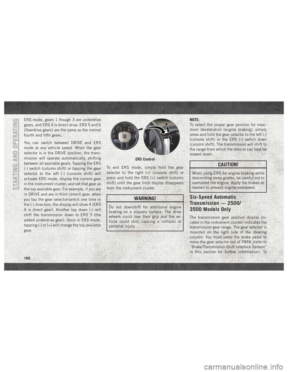
between all available gears. Tapping the ERS
(-) switch (column shift) or tapping the gear
selector to the left (-) (console shift) will
activate ERS mode, display the current gear
in the instrument cluster, and set that gear as
the top available gear. For example, if you are
in DRIVE and are in third (direct) gear, when
you tap the gear selector/switch one time in
the (-) direction, the display will show 4 (ERS
4 is direct gear). Another tap down (-) will
shift the transmission down to ERS 3 (the
added underdrive gear). Once in ERS mode,
tapping (-) or (+) will change the top available
gear.To exit ERS mode, simply hold the gear
selector to the right (+) (console shift) or
press and hold the ERS (+) switch (column
shift) until the gear limit display disappears
from the instrument cluster.
WARNING!
Do not downshift for additional engine
braking on a slippery surface. The drive
wheels could lose their grip and the ve-
hicle could skid, causing a collision or
personal injury.NOTE:
To select the proper gear position for maxi-
mum deceleration (engine braking), simply
press and hold the gear selector to the left (-)
(console shift) or the ERS (-) switch down
(column shift). The transmission will shift to
the range from which the vehicle can best be
slowed down.
CAUTION!
When using ERS for engine braking while
descending steep grades, be careful not to
overspeed the engine. Apply the brakes as
needed to prevent engine overspeed.
Six-Speed Automatic
Transmission — 2500/
3500 Models Only
The transmission gear position display (lo-
cated in the instrument cluster) indicates the
transmission gear range. The gear selector is
mounted on the right side of the steering
column. You must press the brake pedal to
move the gear selector out of PARK (refer to
“Brake/Transmission Shift Interlock System”
in this section for further information). To
ERS Control
STARTING AND OPERATING
160
Page 172 of 372
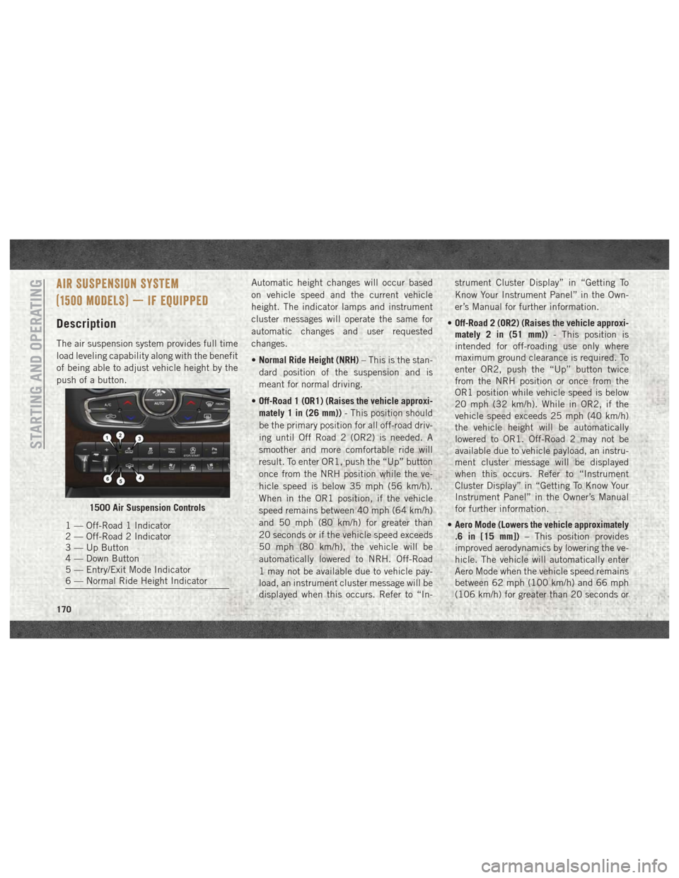
AIR SUSPENSION SYSTEM
(1500 MODELS) — IF EQUIPPED
Description
The air suspension system provides full time
load leveling capability along with the benefit
of being able to adjust vehicle height by the
push of a button.Automatic height changes will occur based
on vehicle speed and the current vehicle
height. The indicator lamps and instrument
cluster messages will operate the same for
automatic changes and user requested
changes.
•
Normal Ride Height (NRH) – This is the stan-
dard position of the suspension and is
meant for normal driving.
• Off-Road 1 (OR1) (Raises the vehicle approxi-
mately 1 in (26 mm)) - This position should
be the primary position for all off-road driv-
ing until Off Road 2 (OR2) is needed. A
smoother and more comfortable ride will
result. To enter OR1, push the “Up” button
once from the NRH position while the ve-
hicle speed is below 35 mph (56 km/h).
When in the OR1 position, if the vehicle
speed remains between 40 mph (64 km/h)
and 50 mph (80 km/h) for greater than
20 seconds or if the vehicle speed exceeds
50 mph (80 km/h), the vehicle will be
automatically lowered to NRH. Off-Road
1 may not be available due to vehicle pay-
load, an instrument cluster message will be
displayed when this occurs. Refer to “In- strument Cluster Display” in “Getting To
Know Your Instrument Panel” in the Own-
er’s Manual for further information.
• Off-Road 2 (OR2) (Raises the vehicle approxi-
mately 2 in (51 mm)) - This position is
intended for off-roading use only where
maximum ground clearance is required. To
enter OR2, push the “Up” button twice
from the NRH position or once from the
OR1 position while vehicle speed is below
20 mph (32 km/h). While in OR2, if the
vehicle speed exceeds 25 mph (40 km/h)
the vehicle height will be automatically
lowered to OR1. Off-Road 2 may not be
available due to vehicle payload, an instru-
ment cluster message will be displayed
when this occurs. Refer to “Instrument
Cluster Display” in “Getting To Know Your
Instrument Panel” in the Owner’s Manual
for further information.
• Aero Mode (Lowers the vehicle approximately
.6 in [15 mm]) – This position provides
improved aerodynamics by lowering the ve-
hicle. The vehicle will automatically enter
Aero Mode when the vehicle speed remains
between 62 mph (100 km/h) and 66 mph
(106 km/h) for greater than 20 seconds or
1500 Air Suspension Controls
1 — Off-Road 1 Indicator
2 — Off-Road 2 Indicator
3 — Up Button
4 — Down Button
5 — Entry/Exit Mode Indicator
6 — Normal Ride Height Indicator
STARTING AND OPERATING
170
Page 174 of 372
NOTE:
This mode is intended to be enabled with
engine running.
Wheel Alignment Mode
Before performing a wheel alignment, this
mode must be enabled. Refer to “Instrument
Cluster Display” in “Getting To Know Your
Instrument Panel” in the Owner’s Manual for
further information.
NOTE:
This mode is intended to be enabled with
engine running.
Protection Strategy
In order to “protect” the air suspension sys-
tem, the vehicle will disable load leveling as
required (suspension overloaded, battery
charge low, etc.). Load leveling will automati-
cally resume as soon as system operation
requirements are met. See your authorized
dealer if system does not resume.
NOTE:
If towing with air suspension refer to “Trailer
Towing” in “Starting And Operating” for fur-
ther information.AIR SUSPENSION SYSTEM (REBEL
MODELS ONLY) — IF EQUIPPED
Description
The air suspension system provides full time
load leveling capability along with the benefit
of being able to adjust vehicle height by the
push of a button.
Automatic height changes will occur based
on vehicle speed and the current vehicle
height. The indicator lamps and instrument
cluster messages will operate the same for
automatic changes and user requested
changes.NOTE:
The vehicle will automatically enter Aero Mode
when the vehicle speed remains between
62 mph (100 km/h) and 66 mph (106 km/h)
for greater than 20 seconds or if the vehicle
speed exceeds 66 mph (106 km/h).
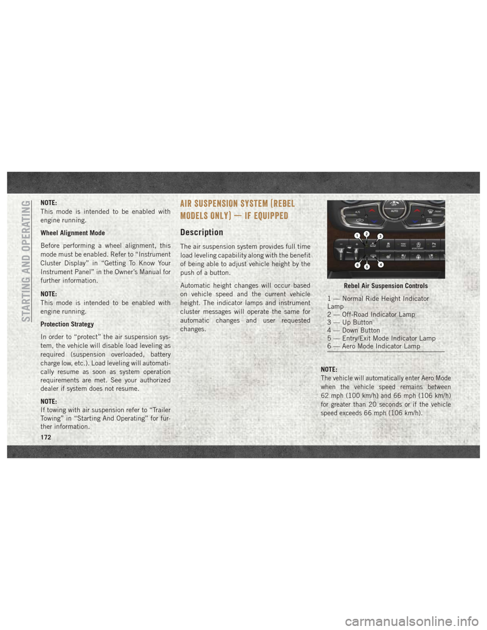
Rebel Air Suspension Controls
1 — Normal Ride Height Indicator
Lamp
2 — Off-Road Indicator Lamp
3 — Up Button
4 — Down Button
5 — Entry/Exit Mode Indicator Lamp
6 — Aero Mode Indicator Lamp
STARTING AND OPERATING
172
Page 175 of 372

•Normal Ride Height (NRH) – This is the stan-
dard position of the suspension and is
meant for normal driving.
• Off-Road (OR) (Raises the vehicle approxi-
mately 1 in (26 mm)) – This position is
intended for off-roading use only where
maximum ground clearance is required. To
enter OR, push the “Up” button once from
the NRH position while vehicle speed is
below 20 mph (32 km/h). While in OR, if
the vehicle speed exceeds 25 mph
(40 km/h) the vehicle height will be auto-
matically lowered to NRH. Off-Road may
not be available due to vehicle payload, an
instrument cluster display message will be
shown when this occurs. Refer to “Instru-
ment Cluster Display” in “Getting To Know
Your Instrument Panel” in your Owner’s
Manual for further information.
• Aero Mode (Lowers the vehicle approximately
.6 in (15 mm)) – This position provides
improved aerodynamics by lowering the ve-
hicle. The vehicle will automatically enter
Aero Mode when the vehicle speed remains
between 62 mph (100 km/h) and 66 mph
(106 km/h) for greater than 20 seconds or
if the vehicle speed exceeds 66 mph (106 km/h). The vehicle will return to NRH
from Aero Mode if the vehicle speed re-
mains between 30 mph (48 km/h) and
35 mph (56 km/h) for greater than 20 sec-
onds or if the vehicle speed falls below
30 mph (48 km/h).
To enter Aero Mode manually push the down
button once from NRH at any vehicle speed.
To return to NRH push the up button once
while vehicle speed is less than 56 mph
(90 km/h).
NOTE:
Automatic Aero Mode may be disabled
through vehicle settings on your Uconnect
Radio when equipped with UConnect 5.0,
8.4A, or 8.4AN. Refer to “Uconnect Set-
tings” in “Multimedia” in your Owner’s
Manual for further information.
• Entry/Exit Mode (Lowers the vehicle approxi-
mately 3 in (73 mm)) – This position lowers
the vehicle for easier passenger entry and
exit as well as lowering the rear of the
vehicle for easier loading and unloading of
cargo. To enter Entry/Exit Mode, push the
“Down” button twice from the NRH while
the vehicle speed is below 33 mph (53 km/ h). Once the vehicle speed goes below
15 mph (24 km/h) the vehicle height will
begin to lower. If the vehicle speed remains
between 15 mph (24 km/h) and 25 mph
(40 km/h) for greater than 60 seconds, or
the vehicle speed exceeds 25 mph
(40 km/h) the Entry/Exit change will be
cancelled. To return to Normal Height
Mode, push the “Up” button twice while in
Entry/Exit or drive the vehicle over 15 mph
(24 km/h). Entry/Exit mode may not be
available due to vehicle payload, an instru-
ment cluster display message will be shown
when this occurs. Refer to “Instrument
Cluster Display” in “Getting To Know Your
Instrument Panel” in your Owner’s Manual
for further information.
Air Suspension Modes
The Air Suspension system has multiple
modes to protect the system in unique situa-
tions:
AERO Mode
To improve aerodynamics, the air suspension
system has a feature which will put the ve-
hicle into AERO height automatically. Refer
173