change time Ram 1500 2018 User Guide
[x] Cancel search | Manufacturer: RAM, Model Year: 2018, Model line: 1500, Model: Ram 1500 2018Pages: 372, PDF Size: 7.1 MB
Page 18 of 372
NOTE:
• The interior lights will turn off if you placethe ignition in the ACC or ON/RUN position
while the Panic Alarm is activated. How-
ever, the exterior lights and horn will remain
on.
• You may need to be less than 35 ft (11 m) from the vehicle when using the key fob to
turn off the Panic Alarm due to the radio
frequency noises emitted by the system.
Air Suspension (Remote Lowering Of The
Vehicle) — If Equipped
For easy entry and loading, your
vehicle can be lowered by push-
ing the key fob air suspension
lowering button two times. When
key fob lowering is requested,
the vehicle will send a series of chirps and
flashes to alert the customer that the opera-
tion has begun and will continue these alerts
until it successfully lowers. The following conditions must be met for the
vehicle to lower remotely:
• The vehicle must not already be in Entry/
Exit (Park) ride height.
• The vehicle battery must be fully charged.
• All doors must be closed.
• The key fob must be out of the vehicle.
Canceling Remote Lowering
Vehicle lowering can be cancelled at any-
time. When vehicle lowering is canceled, the
vehicle will raise up to the next defined level
and lock out the remote lowering feature until
the ignition has been cycled ON/OFF.
To cancel vehicle lowering, push the key fob
air suspension lowering button one time dur-
ing the lowering process. When vehicle low-
ering is canceled, the horn will chirp two
times and the turn signal lamps will flash four
times. Once raising is completed, the horn
will chirp one time.
NOTE:
Refer to “Air Suspension System” in “Start-
ing And Operating” for further information.
General Information
The following regulatory statement applies to
all radio frequency (RF) devices equipped in
this vehicle:
This device complies with Part 15 of the FCC
Rules and with Industry Canada license-
exempt RSS standard(s). Operation is sub-
ject to the following two conditions:
1. This device may not cause harmful inter- ference, and
2. This device must accept any interference received, including interference that may
cause undesired operation.
NOTE:
Changes or modifications not expressly ap-
proved by the party responsible for compli-
ance could void the user’s authority to oper-
ate the equipment.
GETTING TO KNOW YOUR VEHICLE
16
Page 20 of 372
• The engine can be started two consecutivetimes (two 15-minute cycles) with the key
fob. However, the ignition must be placed
in the ON/RUN position before you can
repeat the start sequence for a third cycle.
To Exit Remote Start Mode
Without Driving The Vehicle
Push and release the remote start button one
time or allow the engine to run for the entire
15-minute cycle.
NOTE:
To avoid unintentional shutdowns, the sys-
tem will disable with a one time push of the
remote start button for two seconds after
receiving a valid remote start request.
To Exit Remote Start Mode And
Drive The Vehicle
Before the end of the 15-minute cycle, push
and release the unlock button on the key fob
to unlock the doors and disarm the vehicle
security alarm system (if equipped). Then,
prior to the end of the 15-minute cycle, cycle
the ignition to the ON/RUN position.
General Information
The following regulatory statement applies to
all radio frequency (RF) devices equipped in
this vehicle:
This device complies with Part 15 of the FCC
Rules and with Industry Canada license-
exempt RSS standard(s). Operation is sub-
ject to the following two conditions:
1. This device may not cause harmful inter-
ference, and
2. This device must accept any interference received, including interference that may
cause undesired operation.
NOTE:
Changes or modifications not expressly ap-
proved by the party responsible for compli-
ance could void the user’s authority to oper-
ate the equipment.
VEHICLE SECURITY ALARM
The vehicle security alarm monitors the ve-
hicle doors and ignition for unauthorized op-
eration. When the vehicle security alarm is
activated, interior switches for door locks are disabled. The system provides both audible
and visible signals for the first three minutes.
The horn will sound, the headlights will turn
on, the park lamps and/or turn signals will
flash and vehicle security light will flash
repeatedly. For an additional 15 minutes
only, the headlights will turn on, the park
lamps and/or turn signals, and vehicle secu-
rity light will flash.
To Arm The System
Follow these steps to arm the vehicle security
alarm:
1. Remove the key from the ignition system
(refer to "Starting The Engine" in "Starting
And Operating" for further information).
• For vehicles equipped with Keyless Enter-N-Go — Ignition, make sure the
vehicle ignition system is "OFF."
• For vehicles not equipped with Keyless Enter-N-Go — Ignition, make sure the
vehicle ignition system is "OFF" and
the key is physically removed from the
ignition.
GETTING TO KNOW YOUR VEHICLE
18
Page 27 of 372
Each stored memory setting will have an
associated Easy Entry and Easy Exit position.
NOTE:
The Easy Entry/Exit feature is not enabled
when the vehicle is delivered from the fac-
tory. The Easy Entry/Exit feature is enabled
(or later disabled) through the programmable
features in the Uconnect system. Refer to
“Uconnect Settings” in “Multimedia” in the
Owner’s Manual for further information.
Heated Seats
On some models, the front and rear seats may
be equipped with heaters located in the seat
cushions and seat backs.
WARNING!
• Persons who are unable to feel pain tothe skin because of advanced age,
chronic illness, diabetes, spinal cord in-
jury, medication, alcohol use, exhaus-
tion or other physical condition must
exercise care when using the seat
heater. It may cause burns even at low
WARNING!
temperatures, especially if used for long
periods of time.
•
Do not place anything on the seat or
seatback that insulates against heat, such
as a blanket or cushion. This may cause
the seat heater to overheat. Sitting in a
seat that has been overheated could
cause serious burns due to the increased
surface temperature of the seat.
Front Heated Seats
The front heated seats control buttons are
located on the center instrument panel below
the climate controls.
If your vehicle is equipped with a touch-
screen, the front heated seats control buttons
are also located within the climate or controls
screen of the touchscreen.
• Press the heated seat button
once to
turn the HI setting on.
• Press the heated seat button
a second
time to turn the LO setting on.
• Press the heated seat button
a third
time to turn the heating elements off. When the HI-level setting is selected, the
heater will provide a boosted heat level dur-
ing the first four minutes of operation. Then,
the heat output will drop to the normal HI-
level. If the HI-level setting is selected, the
system will automatically switch to LO-level
after approximately 60 minutes of continu-
ous operation. At that time, the display will
change from HI to LO, indicating the change.
The LO-level setting will turn off automati-
cally after approximately 45 minutes.
NOTE:
The engine must be running for the heated
seats to operate.
Vehicles Equipped With Remote Start
On models that are equipped with remote
start, the driver’s seat can be programmed to
come on during a remote start.
If your vehicle is equipped with a touch-
screen, this feature can be programmed
through the Uconnect system. Refer to
“Uconnect Settings” in “Multimedia” in the
Owner’s Manual for further information.
If your vehicle is not equipped with a touch-
screen, this feature can be programmed
through the instrument cluster display. Refer
25
Page 28 of 372
to “Instrument Cluster Display” in “Getting
To Know Your Instrument Panel” in the Own-
er’s Manual for further information.
Rear Heated Seats
On some models, the two outboard seats are
equipped with heated seats. The heated seat
switches for these seats are located on the
rear of the center console.
There are two heated seat switches that allow
the rear passengers to operate the seats in-
dependently. You can choose from HI, LO or
OFF heat settings. Amber indicator lights in
each switch indicate the level of heat in use.
Two indicator lights will illuminate for HI, one
for LO and none for OFF.Push the switch once
to select HI-level heat-
ing. Push the switch a
second time to select
LO-level heating. Push
the switch a third time
to shut the heating el-
ements OFF. NOTE:
• Once a heat setting is selected, heat will be
felt within two to five minutes.
• The engine must be running for the heated seats to operate.
When the HI-level setting is selected, the
heater will provide a boosted heat level dur-
ing the first four minutes of operation. Then,
the heat output will drop to the normal HI-
level. If the HI-level setting is selected, the
system will automatically switch to LO-level
after approximately 60 minutes of continu-
ous operation. At that time, the number of
illuminated LEDs changes from two to one,
indicating the change. The LO-level setting
will turn OFF automatically after approxi-
mately 45 minutes.
Ventilated Seats — If Equipped
Located in the seat cushion are small fans
that draw the air from the passenger compart-
ment and move air through fine perforations
in the seat cover to help keep the driver and
front passenger cooler in higher ambient
temperatures. The fans operate at two
speeds, HI and LO. The front ventilated seats control buttons are
located on the center instrument panel below
the climate controls.
If your vehicle is equipped with a touch-
screen, the front ventilated seats control but-
tons are also located within the climate or
controls screen of the touchscreen.
• Press the ventilated seat button
once to
choose HI.
• Press the ventilated seat button
a
second time to choose LO.
• Press the ventilated seat button
a third
time to turn the ventilated seat OFF.
NOTE:
The engine must be running for the venti-
lated seats to operate.
Vehicles Equipped With Remote Start
On models that are equipped with remote
start, the ventilated seats can be pro-
grammed to come on during a remote start.
GETTING TO KNOW YOUR VEHICLE
26
Page 36 of 372

Lane Change Assist — If
Equipped
Tap the lever up or down once, without mov-
ing beyond the detent, and the turn signal
(right or left) will flash three times then
automatically turn off.
Cargo Light With Bed Lights — If
Equipped
The cargo light and bed lights (if equipped)
are turned on by pushing the cargo lights
button located just below the headlight
switch.If the vehicle’s speed is 0 mph (0 km/h),
these lights can also be turned on using the
switch located just inside the pickup box. A
telltale will illuminate in the instrument clus-
ter display when this lights are on. Pushing
the switch a second time will turn the lights
off.
The cargo light and bed lights (if equipped)
will turn on for approximately 60 seconds
when a key fob unlock button is pushed, as
part of the Illuminated Entry feature.
Bed Light Switch Without RamBox
Bed Light Switch With RamBox
GETTING TO KNOW YOUR VEHICLE
34
Page 49 of 372
sects. Clean with a gentle water spray from
the front of the radiator and through the
condenser.
MAX A/C
MAX A/C sets the control for maximum cool-
ing performance.
Press and release to toggle between MAX A/C
and the prior settings. The button illuminates
when MAX A/C is on.
In MAX A/C, the blower level and mode posi-
tion can be adjusted to desired user settings.
Pressing other settings will cause the MAX
A/C operation to switch to the selected set-
ting and MAX A/C to exit.
Recirculation
When outside air contains smoke, odors, or
high humidity, or if rapid cooling is desired,
you may wish to recirculate interior air by
pressing the Recirculation control button.
The Recirculation indicator will illuminate
when this button is selected. Press the button
a second time to turn off the Recirculation
mode and allow outside air into the vehicle. NOTE:
In cold weather, use of Recirculation mode
may lead to excessive window fogging. The
Recirculation feature may be unavailable
(button on the touchscreen greyed out) if
conditions exist that could create fogging on
the inside of the windshield.
Automatic Temperature Control
(ATC) — If Equipped
Automatic Operation
1. Push the AUTO button on the faceplate,
or the AUTO button on the touchscreen on
the Automatic Temperature Control (ATC)
Panel.
2. Next, adjust the temperature you would like the system to maintain by adjusting
the driver and passenger temperature
control buttons. Once the desired tem-
perature is displayed, the system will
achieve and automatically maintain that
comfort level.
3. When the system is set up for your comfort level, it is not necessary to change the settings. You will experience the greatest
efficiency by simply allowing the system
to function automatically.
NOTE:
• It is not necessary to move the temperature settings for cold or hot vehicles. The system
automatically adjusts the temperature,
mode, and blower speed to provide comfort
as quickly as possible.
• The temperature can be displayed in U.S. or Metric units by selecting the US/Metric
customer-programmable feature. Refer to
the “Uconnect Settings” in “Multimedia”
in your Owner’s Manual for further
information.
To provide you with maximum comfort in the
Automatic mode during cold start-ups, the
blower fan will remain on low until the engine
warms up. The blower will increase in speed
and transition into Auto mode.
47
Page 55 of 372

NOTE:
For vehicle’s equipped with Keyless Enter-
N-Go, place the ignition in the RUN posi-
tion with the Engine ON. Make sure to
program HomeLink with the vehicle out-
side of the garage, or with the garage door
open at all times.
2. Place the garage door opener transmitter 1 to 3 inches (3 to 8 cm) away from the
HomeLink button you wish to program,
while keeping the HomeLink indicator
light in view.
3. Push and hold the HomeLink button you want to program while you push and hold
the garage door opener transmitter button
you are trying to replicate .
4. Continue to hold both buttons until the Instrument Cluster Display changes from
“CHANNEL # TRAINING” to “CHANNEL
# TRAINED.” Once this happens, release
both buttons. NOTE:
• It may take up to 30 seconds or longer in some cases for the channel to train.
• If “DID NOT TRAIN” appears in the instrument cluster display repeat from
Step 2.
NOTE:
Make sure the garage door opener motor is
plugged in before moving on to the rolling
code/non-rolling code final steps.
Rolling Code Garage Door Opener Final Steps
NOTE:
You have 30 seconds in which to initiate
rolling code final step 2, after completing
rolling code final step 1.
1. At the garage door opener motor (in the garage), locate the “LEARN” or “TRAIN”
button. This can usually be found where
the hanging antenna wire is attached to
the garage door opener motor. Firmly push
and release the “LEARN” or “TRAIN”
button. 2. Return to the vehicle and push the pro-
grammed HomeLink button three times
(holding the button for two seconds each
time). The instrument cluster display will
show “CHANNEL # TRANSMIT”. If the
garage door opener motor operates, pro-
gramming is complete.
3. Push the programmed HomeLink button to confirm that the garage door opener
motor operates. If the garage door opener
motor does not operate, repeat the final
steps for the rolling code procedure.
Non-Rolling Code Garage Door Opener Final
Steps
1. Push and hold the programmed HomeLink button and observe the instru-
ment cluster display. If the instrument
cluster display shows the “CHANNEL #
TRANSMIT,” programming is complete.
2. Push the programmed HomeLink button to confirm that the garage door opener
motor operates. If the garage door opener
motor does not operate, repeat the steps
from the beginning.
53
Page 57 of 372
2. This device must accept any interferencereceived, including interference that may
cause undesired operation.
NOTE:
Changes or modifications not expressly ap-
proved by the party responsible for compli-
ance could void the user’s authority to oper-
ate the equipment.
INTERNAL EQUIPMENT
Electrical Power Outlets
The auxiliary 12 Volt (13 Amp) power outlets
can provide power for in-cab accessories de-
signed for use with the standard “cigar
lighter” plug. The 12 Volt power outlets and
USB Port (Charge Only) have a cap attached
to the outlet indicating “12V DC,” together
with either a key symbol, battery symbol, or
USB symbol. A key symbol indicates that the key must be
in the ON/RUN or ACC positions for the outlet
to provide power. The battery symbol indi-
cates that the outlet is connected to the
battery, and can provide power at all times.
NOTE:
To ensure proper operation, a Mopar knob
and element must be used.
CAUTION!
• Do not exceed the maximum power of
160 Watts (13 Amps) at 12 Volts. If the
160 Watts (13 Amps) power rating is
exceeded, the fuse protecting the sys-
tem will need to be replaced.
• Power outlets are designed for accessory
plugs only. Do not insert any other object
in the power outlets as this will damage
the outlet and blow the fuse. Improper
use of the power outlet can cause dam-
age not covered by your New Vehicle
Limited Warranty. The auxiliary power outlets can be found in
the following locations:
• Lower left and lower right in the center of
the instrument panel – if equipped with a
column or a eight-speed electronic gear
selector.
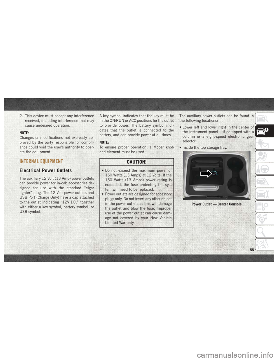
• Inside the top storage tray.
Power Outlet — Center Console
55
Page 70 of 372
tion. At this point the engine Powertrain
Control Module (PCM) will register a fault
code, the instrument panel will display a
MIL light.
CAUTION!
See your authorized dealer, as damage to
the exhaust system could occur soon with
continued operation.
• Exhaust Filter Full — Power Reduced See
Dealer — This message indicates the PCM
has derated the engine to limit the likeli-
hood of permanent damage to the after-
treatment system. If this condition is not
corrected and a dealer service is not per-
formed, extensive exhaust after-treatment
damage can occur. To correct this condition
it will be necessary to have your vehicle
serviced by your local authorized dealer. NOTE:
Failing to follow the oil change indicator,
changing your oil and resetting the oil change
indicator by 0 miles remaining will prevent
the diesel exhaust filter from performing it's
cleaning routine. This will shortly result in a
Malfunction Indicator Light (MIL) and re-
duced engine power. Only an authorized
dealer will be able to correct this condition.
CAUTION!
See your authorized dealer, as damage to
the exhaust system could occur soon with
continued operation.
Diesel Exhaust Fluid (DEF) Warning Mes-
sages
Your vehicle will begin displaying warning
messages when the DEF level reaches a driv-
ing range of approximately 500 miles
(800 km). If the following warning message
sequence is ignored, your vehicle may not
restart unless DEF is added with in the dis-
played mileage shown in the cluster mes-
sage. •
Engine Will Not Restart in XXXX mi DEF Low
Refill Soon — This message will display
when DEF driving range is less than
500 miles, DEF fluid top off is required
with in the displayed mileage. The message
will be displayed in the cluster during ve-
hicle start up with the current allowed mile-
age and accompanied by a single chime.
The remaining mileage can be pulled up
anytime by way of the “Messages” list
within the instrument cluster display.
• Engine Will Not Restart in XXXX mi Refill DEF
— This message will display when DEF
driving range is less than 200 miles. It is
also displayed at 150 miles and 100 miles.
DEF fluid top off is required with in the
displayed mileage. The message will be
displayed in the instrument cluster display
during vehicle start up with an updated
distance mileage, and it will be accompa-
nied by a single chime. Starting at
100 miles, remaining range will be con-
tinuously displayed while operating the ve-
hicle. Chimes will also accompany the 75,
50 and 25 mile remaining distances. The
DEF Low telltale will be on continuously
until DEF fluid is topped off.
GETTING TO KNOW YOUR INSTRUMENT PANEL
68
Page 136 of 372

SAFETY TIPS
Transporting Passengers
NEVER TRANSPORT PASSENGERS IN THE
CARGO AREA.
WARNING!
• Do not leave children or animals insideparked vehicles in hot weather. Interior
heat build-up may cause serious injury
or death.
• It is extremely dangerous to ride in a
cargo area, inside or outside of a vehicle.
In a collision, people riding in these
areas are more likely to be seriously
injured or killed.
• Do not allow people to ride in any area of
your vehicle that is not equipped with
seats and seat belts.
• Be sure everyone in your vehicle is in a
seat and using a seat belt properly.
Exhaust Gas
WARNING!
Exhaust gases can injure or kill. They con-
tain carbon monoxide (CO), which is col-
orless and odorless. Breathing it can make
you unconscious and can eventually poi-
son you. To avoid breathing (CO), follow
these safety tips:
• Do not run the engine in a closed garageor in confined areas any longer than
needed to move your vehicle in or out of
the area.
• If you are required to drive with the
trunk/liftgate/rear doors open, make
sure that all windows are closed and the
climate control BLOWER switch is set at
high speed. DO NOT use the recircula-
tion mode.
• If it is necessary to sit in a parked
vehicle with the engine running, adjust
your heating or cooling controls to force
outside air into the vehicle. Set the
blower at high speed. The best protection against carbon monoxide
entry into the vehicle body is a properly
maintained engine exhaust system.
Whenever a change is noticed in the sound of
the exhaust system, when exhaust fumes can
be detected inside the vehicle, or when the
underside or rear of the vehicle is damaged,
have a competent mechanic inspect the com-
plete exhaust system and adjacent body ar-
eas for broken, damaged, deteriorated, or
mispositioned parts. Open seams or loose
connections could permit exhaust fumes to
seep into the passenger compartment. In
addition, inspect the exhaust system each
time the vehicle is raised for lubrication or oil
change. Replace as required.
Safety Checks You Should Make
Inside The Vehicle
Seat Belts
Inspect the seat belt system periodically,
checking for cuts, frays, and loose parts.
Damaged parts must be replaced immedi-
ately. Do not disassemble or modify the sys-
tem.
SAFETY
134