instrument cluster Ram 1500 2018 Owner's Manual
[x] Cancel search | Manufacturer: RAM, Model Year: 2018, Model line: 1500, Model: Ram 1500 2018Pages: 372, PDF Size: 7.1 MB
Page 35 of 372
Automatic High Beam Headlamp
Control — If Equipped
The Automatic High Beam Headlamp Control
system provides increased forward lighting at
night by automating high beam control
through the use of a digital camera mounted
on the inside rearview mirror. This camera
detects vehicle specific light and automati-
cally switches from high beams to low beams
until the approaching vehicle is out of view.
NOTE:
• The Automatic High Beam Headlamp Con-trol can be turned on or off by selecting
“ON” under “Auto High Beam” within your
Uconnect settings, as well as turning the
headlight switch to the AUTO position. Re-
fer to “Uconnect Settings” in “Multimedia”
in the Owner’s Manual for further informa-
tion.
• Broken, muddy, or obstructed headlights and taillights of vehicles in the field of view
will cause headlights to remain on longer
(closer to the vehicle). Also, dirt, film, and
other obstructions on the windshield or
camera lens will cause the system to func-
tion improperly. If the windshield or Automatic High Beam
Headlamp Control mirror is replaced, the
mirror must be re-aimed to ensure proper
performance. See a local authorized dealer.
Automatic Headlights — If
Equipped
This system automatically turns the head-
lights on or off according to ambient light
levels. To turn the system on, rotate the
headlight switch counterclockwise to the
AUTO position. When the system is on, the
headlight time delay feature is also on. This
means the headlights will stay on for up to
90 seconds after you place the ignition into
the OFF position. The headlight time delay
can be programmed 0/30/60/90 seconds.
Refer to “Uconnect Settings” in “Multime-
dia” in the Owner’s Manual for further infor-
mation.
To turn the automatic system off, move the
headlight switch out of the AUTO position.
NOTE:
The engine must be running before the head-
lights will turn on in the Automatic Mode.
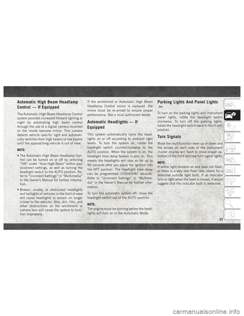
Parking Lights And Panel Lights
To turn on the parking lights and instrument
panel lights, rotate the headlight switch
clockwise. To turn off the parking lights,
rotate the headlight switch back to the O (off)
position.
Turn Signals
Move the multifunction lever up or down and
the arrows on each side of the instrument
cluster display will flash to show proper op-
eration of the front and rear turn signal lights.
NOTE:
If either light remains on and does not flash,
or there is a very fast flash rate, check for a
defective outside light bulb. If an indicator
fails to light when the lever is moved, it would
suggest that the indicator bulb is defective.
33
Page 54 of 372

If you have any problems, or require assis-
tance, please call toll-free 1-800-355-3515
or, on the Internet at HomeLink.com for in-
formation or assistance.
Erasing All The HomeLink
Channels
To erase the channels, follow this procedure:
1. Place the ignition switch into the ON/RUNposition.
NOTE:
For vehicle’s equipped with Keyless
Enter-N-Go, place the ignition in the RUN
position with the Engine ON. Make sure to
program HomeLink with the vehicle out-
side of the garage, or with the garage door
open at all times.
2.
Push and hold the two outside HomeLink
buttons (I and III) for up to 20 seconds, or
until the instrument cluster display
switches from the “Clearing Channels”
message to the “Channels Cleared”
message.
NOTE:
Erasing all channels should only be per-
formed when programming HomeLink for the
first time. Do not erase channels when pro-
gramming additional buttons.
Identifying Whether You Have A
Rolling Code Or Non-Rolling Code
Device
Before programming a device to one of your
HomeLink buttons, you must determine
whether the device has a rolling code or
non-rolling code.
Rolling Code Devices
To determine if your device has a rolling code,
a good indicator is its manufacturing date.
Typically, devices manufactured after
1995 have rolling codes. A device with a
rolling code will also have a “LEARN” or
“TRAIN” button located where the antenna is
attached to the device. The button may not
be immediately visible when looking at the
device. The name and color of the button may
vary slightly by manufacturer. NOTE:
The “LEARN” or “TRAIN” button is not the
button you normally use to operate the de-
vice.
Non-rolling Code Devices
Most devices manufactured before 1995 will
not have a rolling code. These devices will
also not have a “LEARN” or “TRAIN” button.Programming HomeLink To A
Garage Door Opener
To program any of the HomeLink buttons to
activate your garage door opener motor, fol-
low the steps below:
NOTE:
All HomeLink buttons are programmed using
this procedure. You do not need to erase all
channels when programming additional but-
tons.
1. Place the ignition switch into the ON/RUN
position.
GETTING TO KNOW YOUR VEHICLE
52
Page 55 of 372

NOTE:
For vehicle’s equipped with Keyless Enter-
N-Go, place the ignition in the RUN posi-
tion with the Engine ON. Make sure to
program HomeLink with the vehicle out-
side of the garage, or with the garage door
open at all times.
2. Place the garage door opener transmitter 1 to 3 inches (3 to 8 cm) away from the
HomeLink button you wish to program,
while keeping the HomeLink indicator
light in view.
3. Push and hold the HomeLink button you want to program while you push and hold
the garage door opener transmitter button
you are trying to replicate .
4. Continue to hold both buttons until the Instrument Cluster Display changes from
“CHANNEL # TRAINING” to “CHANNEL
# TRAINED.” Once this happens, release
both buttons. NOTE:
• It may take up to 30 seconds or longer in some cases for the channel to train.
• If “DID NOT TRAIN” appears in the instrument cluster display repeat from
Step 2.
NOTE:
Make sure the garage door opener motor is
plugged in before moving on to the rolling
code/non-rolling code final steps.
Rolling Code Garage Door Opener Final Steps
NOTE:
You have 30 seconds in which to initiate
rolling code final step 2, after completing
rolling code final step 1.
1. At the garage door opener motor (in the garage), locate the “LEARN” or “TRAIN”
button. This can usually be found where
the hanging antenna wire is attached to
the garage door opener motor. Firmly push
and release the “LEARN” or “TRAIN”
button. 2. Return to the vehicle and push the pro-
grammed HomeLink button three times
(holding the button for two seconds each
time). The instrument cluster display will
show “CHANNEL # TRANSMIT”. If the
garage door opener motor operates, pro-
gramming is complete.
3. Push the programmed HomeLink button to confirm that the garage door opener
motor operates. If the garage door opener
motor does not operate, repeat the final
steps for the rolling code procedure.
Non-Rolling Code Garage Door Opener Final
Steps
1. Push and hold the programmed HomeLink button and observe the instru-
ment cluster display. If the instrument
cluster display shows the “CHANNEL #
TRANSMIT,” programming is complete.
2. Push the programmed HomeLink button to confirm that the garage door opener
motor operates. If the garage door opener
motor does not operate, repeat the steps
from the beginning.
53
Page 56 of 372

WARNING!
• Your motorized door or gate will openand close while you are programming
the universal transceiver. Do not pro-
gram the transceiver if people or pets are
in the path of the door or gate.
• Do not run your vehicle in a closed
garage or confined area while program-
ming the transceiver. Exhaust gas from
your vehicle contains Carbon Monoxide
(CO) which is odorless and colorless.
Carbon Monoxide is poisonous when in-
haled and can cause you and others to
be severely injured or killed.
Programming HomeLink To A
Miscellaneous Device
Refer to “Programming HomeLink To A Ga-
rage Door Opener” for the procedure on how
to program HomeLink to a miscellaneous
device, as it follows the same procedure. Be
sure to determine if the device has a rolling
code, or non-rolling code before beginning
the programming process. NOTE:
Canadian radio frequency laws require trans-
mitter signals to time-out (or quit) after sev-
eral seconds of transmission, which may not
be long enough for HomeLink to pick up the
signal during programming. Similar to this
Canadian law, some U.S. gate operators are
designed to time-out in the same manner.
The procedure may need to be preformed
multiple times to successfully pair the device
to your HomeLink buttons.
Reprogramming A Single
HomeLink Button
To reprogram a single HomeLink button that
has been previously trained, without erasing
all the channels, follow the procedure below.
Be sure to determine whether the new device
you want to program the HomeLink button to
has a Rolling Code, or Non-rolling Code.
1. Cycle the ignition to the ON/RUN
position. NOTE:
For vehicle’s equipped with Keyless
Enter-N-Go, place the ignition in the RUN
position with the Engine ON. Make sure to
program HomeLink with the vehicle out-
side of the garage, or with the garage door
open at all times.
2. Push and hold the desired HomeLink but- ton until the instrument cluster display
shows the “CHANNEL # TRAINING”
message. Do not release the button.
3. Without releasing the button, proceed with
Step 2 in “Programming HomeLink To A
Garage Door Opener” and follow all re-
maining steps.
General Information
The following regulatory statement applies to
all Radio Frequency (RF) devices equipped in
this vehicle:
This device complies with Part 15 of the FCC
Rules and with Industry Canada license-
exempt RSS standard(s). Operation is sub-
ject to the following two conditions:
1. This device may not cause harmful inter- ference, andGETTING TO KNOW YOUR VEHICLE
54
Page 67 of 372
GETTING TO KNOW YOUR INSTRUMENT PANEL
INSTRUMENT CLUSTER DISPLAY.....66
Instrument Cluster Display Controls ....66
Diesel Messages And Warnings — 3.0L
Diesel Engine .................67
Diesel Messages And Warnings — 6.7L
Cummins Diesel Engine ...........70
Oil Life Reset .................74
Instrument Cluster Display Programmable
Features ....................75
WARNING LIGHTS AND MESSAGES ....76
Red Warning Lights..............76
Yellow Warning Lights ............78
Yellow Indicator Lights ............82
Green Indicator Lights ............83
White Indicator Lights ............84
Blue Indicator Lights .............84
ONBOARD DIAGNOSTIC SYSTEM —
OBDII .....................84
Onboard Diagnostic System (OBD II)
Cybersecurity.................85
GETTING TO KNOW YOUR INSTRUMENT PANEL
65
Page 68 of 372
INSTRUMENT CLUSTER DISPLAY
Your vehicle may be equipped with an instru-
ment cluster display, which offers useful in-
formation to the driver. With the ignition in
the STOP/OFF mode, opening/closing of a
door will activate the display for viewing, and
display the total miles, or kilometers, in the
odometer. Your instrument cluster display is
designed to display important information
about your vehicle’s systems and features.
Using a driver interactive display located on
the instrument panel, your instrument clus-
ter display can show you how systems are
working and give you warnings when they are
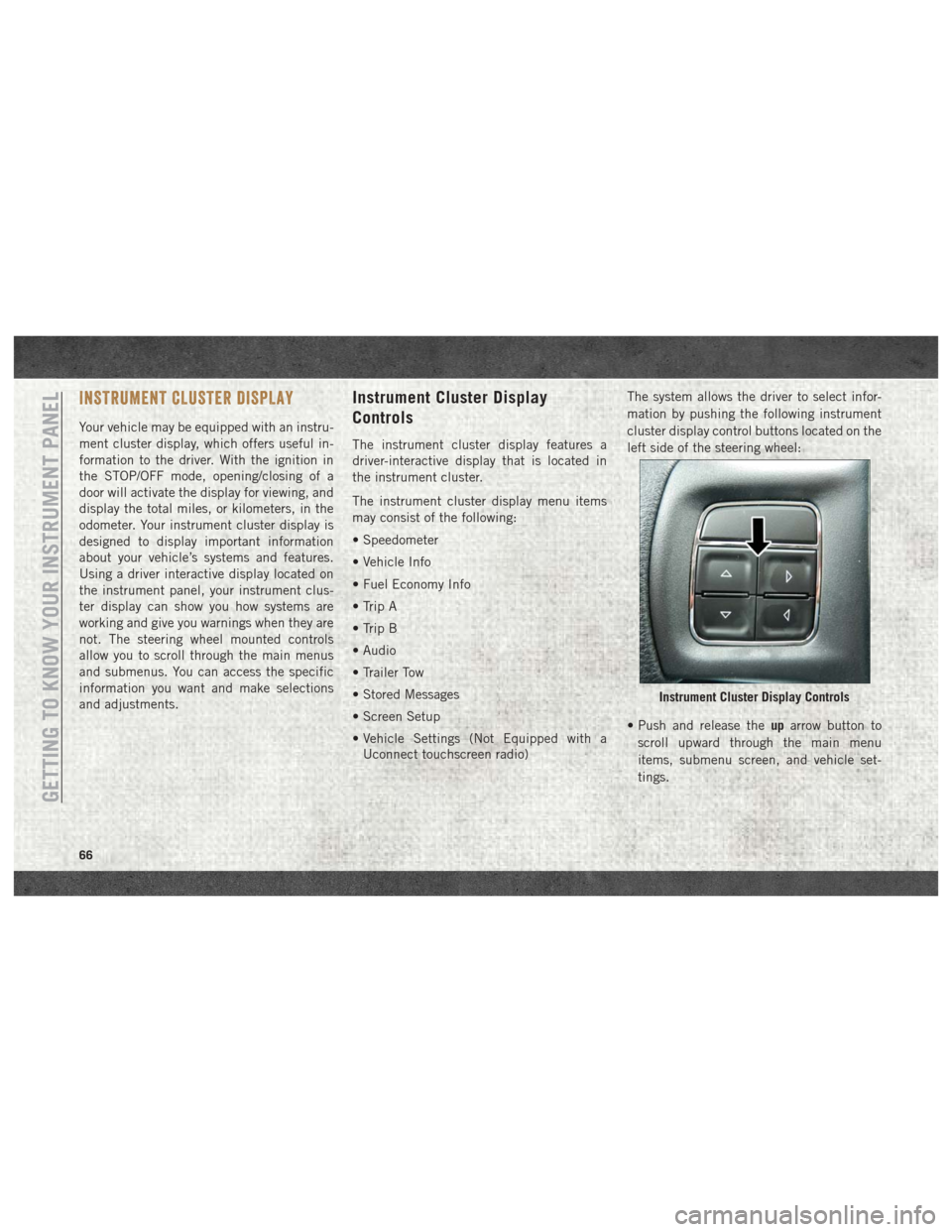
not. The steering wheel mounted controls
allow you to scroll through the main menus
and submenus. You can access the specific
information you want and make selections
and adjustments.
Instrument Cluster Display
Controls
The instrument cluster display features a
driver-interactive display that is located in
the instrument cluster.
The instrument cluster display menu items
may consist of the following:
• Speedometer
• Vehicle Info
• Fuel Economy Info
• Trip A
• Trip B
• Audio
• Trailer Tow
• Stored Messages
• Screen Setup
• Vehicle Settings (Not Equipped with aUconnect touchscreen radio) The system allows the driver to select infor-
mation by pushing the following instrument
cluster display control buttons located on the
left side of the steering wheel:
• Push and release the
uparrow button to
scroll upward through the main menu
items, submenu screen, and vehicle set-
tings.
Instrument Cluster Display Controls
GETTING TO KNOW YOUR INSTRUMENT PANEL
66
Page 69 of 372
• Push and release thedownarrow button to
scroll downward through the main menu
items, submenu screen, and vehicle set-
tings.
• Push and release the rightarrow button to
access/select the information screens or
submenu screens of a main menu item.
Push and hold the RIGHT arrow button for
two seconds to reset displayed/selected
features that can be reset.
• Push and release the leftarrow button to
access/select the information screens, sub-
menu screens of a main menu item, or to
return to the main menu.
Diesel Messages And Warnings —
3.0L Diesel Engine
Diesel Particulate Filter (DPF) Messages
WARNING!
A hot exhaust system can start a fire if you
park over materials that can burn. Such
materials might be grass or leaves coming
into contact with your exhaust system. Do
WARNING!
not park or operate your vehicle in areas
where your exhaust system can contact
anything that can burn.
Your vehicle has the ability to alert you to
additional maintenance required on your ve-
hicle or engine. Refer to the following mes-
sages that may be displayed on your instru-
ment cluster:
• Exhaust Filter XX% Full Safely Drive at High-
way Speeds to Remedy — This message will
be displayed in the instrument cluster if the
exhaust particulate filter reaches 80% of
its maximum storage capacity. Under con-
ditions of exclusive short duration and low
speed driving cycles, your diesel engine
and exhaust after-treatment system may
never reach the conditions required to
cleanse the filter to remove the trapped
PM. If this occurs, the “Exhaust Filter XX%
Full Safely Drive at Highway Speeds to
Remedy” message will be displayed in the
instrument cluster display. If this message
is displayed, you will hear one chime to
assist in alerting you of this condition. By simply driving your vehicle at highway
speeds for up to 20 minutes, you can rem-
edy the condition in the particulate filter
system and allow your diesel engine and
exhaust after-treatment system to cleanse
the filter to remove the trapped PM and
restore the system to normal operating con-
dition.
• Exhaust System — Regeneration In Process
Exhaust Filter XX% Full — This message
indicates that the Diesel Particulate Filter
(DPF) is self-cleaning. Maintain your cur-
rent driving condition until regeneration is
completed.
• Exhaust System — Regeneration Completed
— This message indicates that the Diesel
Particulate Filter (DPF) self-cleaning is
completed. If this message is displayed,
you will hear one chime to assist in alerting
you of this condition.
• Exhaust Service Required — See Dealer Now
— This messages indicates regeneration
has been disabled due to a system malfunc-
67
Page 70 of 372
tion. At this point the engine Powertrain
Control Module (PCM) will register a fault
code, the instrument panel will display a
MIL light.
CAUTION!
See your authorized dealer, as damage to
the exhaust system could occur soon with
continued operation.
• Exhaust Filter Full — Power Reduced See
Dealer — This message indicates the PCM
has derated the engine to limit the likeli-
hood of permanent damage to the after-
treatment system. If this condition is not
corrected and a dealer service is not per-
formed, extensive exhaust after-treatment
damage can occur. To correct this condition
it will be necessary to have your vehicle
serviced by your local authorized dealer. NOTE:
Failing to follow the oil change indicator,
changing your oil and resetting the oil change
indicator by 0 miles remaining will prevent
the diesel exhaust filter from performing it's
cleaning routine. This will shortly result in a
Malfunction Indicator Light (MIL) and re-
duced engine power. Only an authorized
dealer will be able to correct this condition.
CAUTION!
See your authorized dealer, as damage to
the exhaust system could occur soon with
continued operation.
Diesel Exhaust Fluid (DEF) Warning Mes-
sages
Your vehicle will begin displaying warning
messages when the DEF level reaches a driv-
ing range of approximately 500 miles
(800 km). If the following warning message
sequence is ignored, your vehicle may not
restart unless DEF is added with in the dis-
played mileage shown in the cluster mes-
sage. •
Engine Will Not Restart in XXXX mi DEF Low
Refill Soon — This message will display
when DEF driving range is less than
500 miles, DEF fluid top off is required
with in the displayed mileage. The message
will be displayed in the cluster during ve-
hicle start up with the current allowed mile-
age and accompanied by a single chime.
The remaining mileage can be pulled up
anytime by way of the “Messages” list
within the instrument cluster display.
• Engine Will Not Restart in XXXX mi Refill DEF
— This message will display when DEF
driving range is less than 200 miles. It is
also displayed at 150 miles and 100 miles.
DEF fluid top off is required with in the
displayed mileage. The message will be
displayed in the instrument cluster display
during vehicle start up with an updated
distance mileage, and it will be accompa-
nied by a single chime. Starting at
100 miles, remaining range will be con-
tinuously displayed while operating the ve-
hicle. Chimes will also accompany the 75,
50 and 25 mile remaining distances. The
DEF Low telltale will be on continuously
until DEF fluid is topped off.
GETTING TO KNOW YOUR INSTRUMENT PANEL
68
Page 72 of 372
See Dealer message is displayed on the
next subsequent restart. Your engine will
not start unless your vehicle is serviced by
your authorized dealer. The message will be
accompanied by a single chime. Your Mal-
function Indicator Light will be continu-
ously illuminated. If the message appears
and you can not start the engine, we rec-
ommend you have your vehicle towed to
your nearest authorized dealer
immediately.
Diesel Messages And Warnings
— 6.7L Cummins Diesel Engine
Diesel Particulate Filter (DPF) Messages
The Cummins diesel engine meets all diesel
emissions standards, resulting in one of the
lowest emitting diesel engines ever pro-
duced. To achieve these emissions stan-
dards, your vehicle is equipped with a state-
of-the-art engine and exhaust system. These
systems are seamlessly integrated into your
vehicle and managed by the Powertrain Con-
trol Module (PCM). The PCM manages enginecombustion to allow the exhaust system’s
catalyst to trap and burn Particulate Matter
(PM) pollutants, with no input or interaction
on your part.
WARNING!
A hot exhaust system can start a fire if you
park over materials that can burn. Such
materials might be grass or leaves coming
into contact with your exhaust system. Do
not park or operate your vehicle in areas
where your exhaust system can contact
anything that can burn.
Your vehicle has the ability to alert you to
additional maintenance required on your ve-
hicle or engine. The following messages may
display in your instrument cluster display:
• Perform Service — Your vehicle will require
emissions maintenance at a set interval. To
help remind you when this maintenance is
due, the instrument cluster display will
display “Perform Service”. When the “Per-
form Service” message is displayed in the
instrument cluster display it is necessary to
have the emissions maintenance per-
formed. Emissions maintenance may in- clude replacing the Closed Crankcase Ven-
tilation (CCV) filter element. The procedure
for clearing and resetting the "Perform Ser-
vice" indicator message is located in the
appropriate Service Information.
• Exhaust System — Regeneration Required
Now — "Exhaust Filter XX% Full Safely
Drive at Highway Speeds to Remedy" will
be displayed in the instrument cluster dis-
play if the exhaust particulate filter reaches
80% of its maximum storage capacity. Un-
der conditions of exclusive short duration
and low speed driving cycles, your Cum-
mins diesel engine and exhaust after-
treatment system may never reach the con-
ditions required to remove the trapped PM.
If this occurs, the “Exhaust Filter XX% Full
Safely Drive at Highway Speeds to Rem-
edy” message will be displayed in the in-
strument cluster display. If this message is
displayed, you will hear one chime to assist
in alerting you of this condition
By simply driving your vehicle at highway
speeds for as little as 45 minutes, you can
remedy the condition in the particulate filter
system and allow your Cummins diesel en-
gine and exhaust after-treatment system to
GETTING TO KNOW YOUR INSTRUMENT PANEL
70
Page 76 of 372
under demanding hot or high altitude condi-
tions. If the instrument cluster display dis-
plays the message “Active Airbox Service
Required See Dealer”, vehicle performance
may be reduced until service is performed by
an authorized RAM dealer.
Oil Life Reset
Your vehicle is equipped with an engine oil
change indicator system. The “Oil Change
Required” message will display in the instru-
ment cluster display after a single chime has
sounded, to indicate the next scheduled oil
change interval. The engine oil change indi-
cator system is duty cycle based, which
means the engine oil change interval may
fluctuate, dependent upon your personal
driving style.
NOTE:
Use the steering wheel instrument cluster
display controls for the following proce-
dure(s).Vehicles Equipped With Passive Entry
1. Without pushing the brake pedal, push
the ENGINE START/STOP button and
place the ignition to the ON/RUN position
(do not start the engine).
2. Push and release the downarrow button to
scroll downward through the main menu
to “Vehicle Info.”
3. Push and release the rightarrow button to
access the ”Vehicle Info” screen, then
scroll up or down to select “Oil Life.”
4. Push and hold the rightarrow button to
select “Reset”.
5. Push and release the downarrow button to
select “Yes,” then push and release the
right arrow button to select reset of the Oil
Life to 100%.
6. Push and release the uparrow button to
exit the instrument cluster display screen. Vehicles Not Equipped With Passive Entry
1. Without pushing the brake pedal, cycle
the ignition to the ON/RUN position (do
not start the engine).
2. Push and release the downarrow button to
scroll downward through the main menu
to “Vehicle Info.”
3. Push and release the rightarrow button to
access the “Vehicle Info” screen then
scroll up or down to select “Oil Life.”
4. Push and hold the rightarrow button to
select “YES” by pushing the rightarrow
then push and release the rightarrow
button to select reset of the Oil Life to
100%.
5. Push and release the uparrow button to
exit the instrument cluster display screen.
NOTE:
If the indicator message illuminates when
you start the vehicle, the Oil Life indicator
system did not reset. If necessary, repeat this
procedure.
GETTING TO KNOW YOUR INSTRUMENT PANEL
74