light Ram 1500 2018 Owner's Manual
[x] Cancel search | Manufacturer: RAM, Model Year: 2018, Model line: 1500, Model: Ram 1500 2018Pages: 372, PDF Size: 7.1 MB
Page 36 of 372

Lane Change Assist — If
Equipped
Tap the lever up or down once, without mov-
ing beyond the detent, and the turn signal
(right or left) will flash three times then
automatically turn off.
Cargo Light With Bed Lights — If
Equipped
The cargo light and bed lights (if equipped)
are turned on by pushing the cargo lights
button located just below the headlight
switch.If the vehicle’s speed is 0 mph (0 km/h),
these lights can also be turned on using the
switch located just inside the pickup box. A
telltale will illuminate in the instrument clus-
ter display when this lights are on. Pushing
the switch a second time will turn the lights
off.
The cargo light and bed lights (if equipped)
will turn on for approximately 60 seconds
when a key fob unlock button is pushed, as
part of the Illuminated Entry feature.
Bed Light Switch Without RamBox
Bed Light Switch With RamBox
GETTING TO KNOW YOUR VEHICLE
34
Page 41 of 372

IconDescription
Temperature Control
Press the arrows on the touchscreen or faceplate to regulate the temperature of the air inside the passenger compart-
ment. Pressing the down arrow indicates cooler temperatures, and pressing the up arrow indicates warmer tempera-
tures.
Blower Control
There are seven blower speeds. Press the buttons to regulate the amount of air forced through the system in any mode
you select. The blower speed increases as you move the control clockwise from the off position.
Panel Mode
Panel Mode
Air comes from the outlets in the instrument panel. Each of these outlets can be individually adjusted to direct the flow
of air. The air vanes of the center outlets and outboard outlets can be moved up and down or side to side to regulate
airflow direction. There is a shut off wheel located below the air vanes to shut off or adjust the amount of airflow from
these outlets.
Bi-Level Mode
Bi-Level Mode
Air comes from the instrument panel outlets and floor outlets. A slight amount of air is directed through the defrost and
side window demister outlets.
NOTE:
Bi-Level mode is designed under comfort conditions to provide cooler air out of the panel outlets and warmer air from
the floor outlets.
Floor Mode
Floor Mode
Air comes from the floor outlets. A slight amount of air is directed through the defrost and side window demister out-
lets.
39
Page 47 of 372

IconDescription
SYNC Button — If Equipped
Press the SYNC button on the touchscreen to toggle the SYNC feature on/off. The SYNC indicator is illuminated when
this feature is enabled. SYNC is used to synchronize the passenger temperature setting with the driver temperature set-
ting. The SYNC feature also synchronizes the rear passengers’ temperature to the driver temperature setting. Changing
the passenger temperature setting while in SYNC will automatically exit this feature.
Faceplate Knob
Touchscreen Buttons
Blower Control
Blower Control is used to regulate the amount of air forced through the climate system. There are seven blower speeds
available. The speeds can be selected using either the blower control knob on the faceplate or the buttons on the touch-
screen.
• Faceplate: The blower speed increases as you turn the blower control knob clockwise from the lowest blower setting. The
blower speed decreases as you turn the blower control knob counterclockwise.
• Touchscreen:
Use the small blower icon to reduce the blower setting and the large blower icon to increase the blower
setting. Blower can also be selected by pressing the blower bar area between the icons. For Uconnect 3, press the button
to access the blower screen and control the blower.
Panel Mode
Panel Mode
Air comes from the outlets in the instrument panel. Each of these outlets can be individually adjusted to direct the flow
of air. The air vanes of the center outlets and outboard outlets can be moved up and down or side to side to regulate
airflow direction. There is a shut off wheel located below the air vanes to shut off or adjust the amount of airflow from
these outlets.
Bi-Level Mode
Bi-Level Mode
Air comes from the instrument panel outlets and floor outlets. A slight amount of air is directed through the defrost and
side window demister outlets.
NOTE:
Bi-Level mode is designed under comfort conditions to provide cooler air out of the panel outlets and warmer air from
the floor outlets.
45
Page 48 of 372
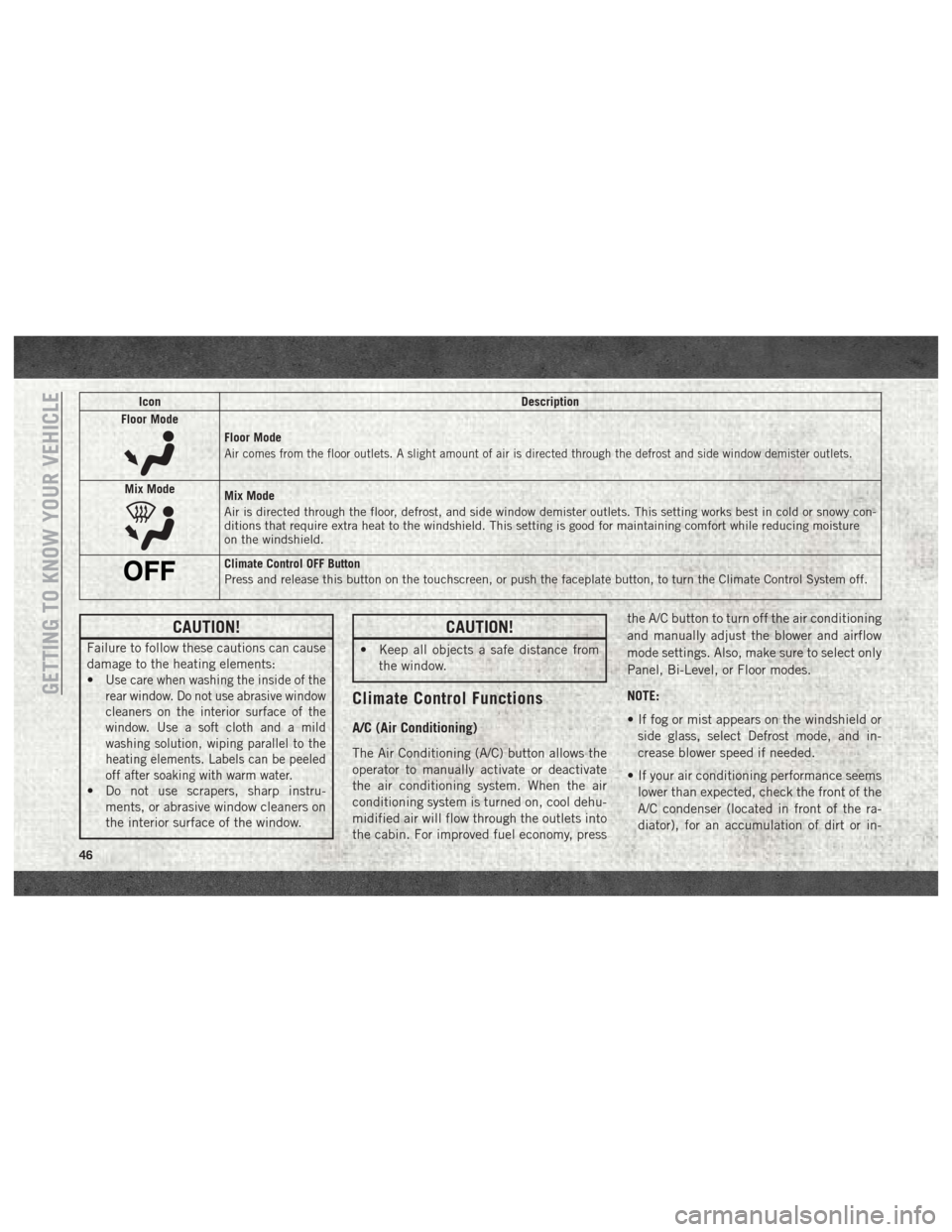
IconDescription
Floor Mode
Floor Mode
Air comes from the floor outlets. A slight amount of air is directed through the defrost and side window demister outlets.
Mix ModeMix Mode
Air is directed through the floor, defrost, and side window demister outlets. This setting works best in cold or snowy con-
ditions that require extra heat to the windshield. This setting is good for maintaining comfort while reducing moisture
on the windshield.
Climate Control OFF Button
Press and release this button on the touchscreen, or push the faceplate button, to turn the Climate Control System off.
CAUTION!
Failure to follow these cautions can cause
damage to the heating elements:
•
Use care when washing the inside of the
rear window. Do not use abrasive window
cleaners on the interior surface of the
window. Use a soft cloth and a mild
washing solution, wiping parallel to the
heating elements. Labels can be peeled
off after soaking with warm water.
• Do not use scrapers, sharp instru- ments, or abrasive window cleaners on
the interior surface of the window.
CAUTION!
• Keep all objects a safe distance from
the window.
Climate Control Functions
A/C (Air Conditioning)
The Air Conditioning (A/C) button allows the
operator to manually activate or deactivate
the air conditioning system. When the air
conditioning system is turned on, cool dehu-
midified air will flow through the outlets into
the cabin. For improved fuel economy, press the A/C button to turn off the air conditioning
and manually adjust the blower and airflow
mode settings. Also, make sure to select only
Panel, Bi-Level, or Floor modes.
NOTE:
• If fog or mist appears on the windshield or
side glass, select Defrost mode, and in-
crease blower speed if needed.
• If your air conditioning performance seems lower than expected, check the front of the
A/C condenser (located in front of the ra-
diator), for an accumulation of dirt or in-
GETTING TO KNOW YOUR VEHICLE
46
Page 51 of 372
POWER SUNROOF — IF EQUIPPED
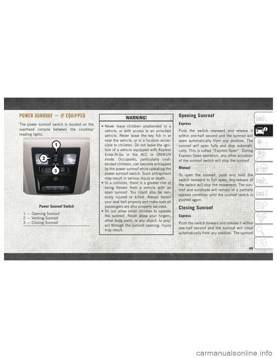
The power sunroof switch is located on the
overhead console between the courtesy/
reading lights.
WARNING!
• Never leave children unattended in avehicle, or with access to an unlocked
vehicle. Never leave the key fob in or
near the vehicle, or in a location acces-
sible to children. Do not leave the igni-
tion of a vehicle equipped with Keyless
Enter-N-Go in the ACC or ON/RUN
mode. Occupants, particularly unat-
tended children, can become entrapped
by the power sunroof while operating the
power sunroof switch. Such entrapment
may result in serious injury or death.
• In a collision, there is a greater risk of
being thrown from a vehicle with an
open sunroof. You could also be seri-
ously injured or killed. Always fasten
your seat belt properly and make sure all
passengers are also properly secured.
• Do not allow small children to operate
the sunroof. Never allow your fingers,
other body parts, or any object, to proj-
ect through the sunroof opening. Injury
may result.
Opening Sunroof
Express
Push the switch rearward and release it
within one-half second and the sunroof will
open automatically from any position. The
sunroof will open fully and stop automati-
cally. This is called “Express Open”. During
Express Open operation, any other actuation
of the sunroof switch will stop the sunroof.
Manual
To open the sunroof, push and hold the
switch rearward to full open. Any release of
the switch will stop the movement. The sun-
roof and sunshade will remain in a partially
opened condition until the sunroof switch is
pushed again.
Closing Sunroof
Express
Push the switch forward and release it within
one-half second and the sunroof will close
automatically from any position. The sunroof
Power Sunroof Switch
1 — Opening Sunroof
2 — Venting Sunroof
3 — Closing Sunroof
49
Page 53 of 372
2. Reach into the opening beneath the cen-ter of the hood and push the safety latch
lever to the left to release it, before raising
the hood.
To Close The Hood
Lower the hood to approximately 12 inches
(30 cm) from the engine compartment and
drop it. Make sure that the hood is completely
closed.
WARNING!
Be sure the hood is fully latched before
driving your vehicle. If the hood is not fully
latched, it could open when the vehicle is
in motion and block your vision. Failure to
follow this warning could result in serious
injury or death.
CAUTION!
To prevent possible damage, do not slam
the hood to close it. Use a firm downward
push at the front center of the hood to
ensure that both latches engage.
UNIVERSAL GARAGE DOOR OPENER
(HOMELINK)
• HomeLink replaces up to three hand-heldtransmitters that operate devices such as
garage door openers, motorized gates,
lighting or home security systems. The
HomeLink unit is powered by your vehicles
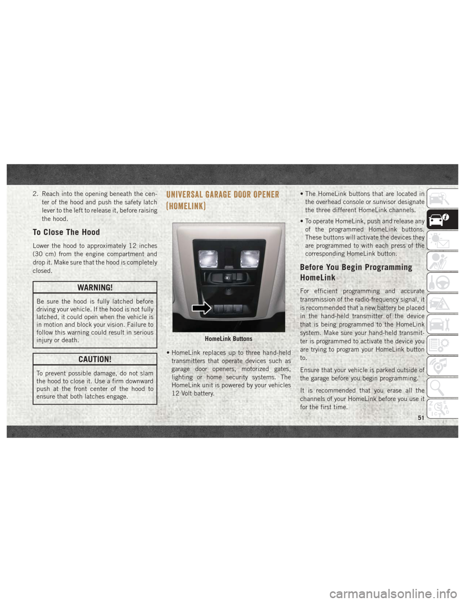
12 Volt battery. • The HomeLink buttons that are located in
the overhead console or sunvisor designate
the three different HomeLink channels.
• To operate HomeLink, push and release any of the programmed HomeLink buttons.
These buttons will activate the devices they
are programmed to with each press of the
corresponding HomeLink button.
Before You Begin Programming
HomeLink
For efficient programming and accurate
transmission of the radio-frequency signal, it
is recommended that a new battery be placed
in the hand-held transmitter of the device
that is being programmed to the HomeLink
system. Make sure your hand-held transmit-
ter is programmed to activate the device you
are trying to program your HomeLink button
to.
Ensure that your vehicle is parked outside of
the garage before you begin programming.
It is recommended that you erase all the
channels of your HomeLink before you use it
for the first time.
HomeLink Buttons
51
Page 54 of 372

If you have any problems, or require assis-
tance, please call toll-free 1-800-355-3515
or, on the Internet at HomeLink.com for in-
formation or assistance.
Erasing All The HomeLink
Channels
To erase the channels, follow this procedure:
1. Place the ignition switch into the ON/RUNposition.
NOTE:
For vehicle’s equipped with Keyless
Enter-N-Go, place the ignition in the RUN
position with the Engine ON. Make sure to
program HomeLink with the vehicle out-
side of the garage, or with the garage door
open at all times.
2.
Push and hold the two outside HomeLink
buttons (I and III) for up to 20 seconds, or
until the instrument cluster display
switches from the “Clearing Channels”
message to the “Channels Cleared”
message.
NOTE:
Erasing all channels should only be per-
formed when programming HomeLink for the
first time. Do not erase channels when pro-
gramming additional buttons.
Identifying Whether You Have A
Rolling Code Or Non-Rolling Code
Device
Before programming a device to one of your
HomeLink buttons, you must determine
whether the device has a rolling code or
non-rolling code.
Rolling Code Devices
To determine if your device has a rolling code,
a good indicator is its manufacturing date.
Typically, devices manufactured after
1995 have rolling codes. A device with a
rolling code will also have a “LEARN” or
“TRAIN” button located where the antenna is
attached to the device. The button may not
be immediately visible when looking at the
device. The name and color of the button may
vary slightly by manufacturer. NOTE:
The “LEARN” or “TRAIN” button is not the
button you normally use to operate the de-
vice.
Non-rolling Code Devices
Most devices manufactured before 1995 will
not have a rolling code. These devices will
also not have a “LEARN” or “TRAIN” button.Programming HomeLink To A
Garage Door Opener
To program any of the HomeLink buttons to
activate your garage door opener motor, fol-
low the steps below:
NOTE:
All HomeLink buttons are programmed using
this procedure. You do not need to erase all
channels when programming additional but-
tons.
1. Place the ignition switch into the ON/RUN
position.
GETTING TO KNOW YOUR VEHICLE
52
Page 55 of 372

NOTE:
For vehicle’s equipped with Keyless Enter-
N-Go, place the ignition in the RUN posi-
tion with the Engine ON. Make sure to
program HomeLink with the vehicle out-
side of the garage, or with the garage door
open at all times.
2. Place the garage door opener transmitter 1 to 3 inches (3 to 8 cm) away from the
HomeLink button you wish to program,
while keeping the HomeLink indicator
light in view.
3. Push and hold the HomeLink button you want to program while you push and hold
the garage door opener transmitter button
you are trying to replicate .
4. Continue to hold both buttons until the Instrument Cluster Display changes from
“CHANNEL # TRAINING” to “CHANNEL
# TRAINED.” Once this happens, release
both buttons. NOTE:
• It may take up to 30 seconds or longer in some cases for the channel to train.
• If “DID NOT TRAIN” appears in the instrument cluster display repeat from
Step 2.
NOTE:
Make sure the garage door opener motor is
plugged in before moving on to the rolling
code/non-rolling code final steps.
Rolling Code Garage Door Opener Final Steps
NOTE:
You have 30 seconds in which to initiate
rolling code final step 2, after completing
rolling code final step 1.
1. At the garage door opener motor (in the garage), locate the “LEARN” or “TRAIN”
button. This can usually be found where
the hanging antenna wire is attached to
the garage door opener motor. Firmly push
and release the “LEARN” or “TRAIN”
button. 2. Return to the vehicle and push the pro-
grammed HomeLink button three times
(holding the button for two seconds each
time). The instrument cluster display will
show “CHANNEL # TRANSMIT”. If the
garage door opener motor operates, pro-
gramming is complete.
3. Push the programmed HomeLink button to confirm that the garage door opener
motor operates. If the garage door opener
motor does not operate, repeat the final
steps for the rolling code procedure.
Non-Rolling Code Garage Door Opener Final
Steps
1. Push and hold the programmed HomeLink button and observe the instru-
ment cluster display. If the instrument
cluster display shows the “CHANNEL #
TRANSMIT,” programming is complete.
2. Push the programmed HomeLink button to confirm that the garage door opener
motor operates. If the garage door opener
motor does not operate, repeat the steps
from the beginning.
53
Page 57 of 372
2. This device must accept any interferencereceived, including interference that may
cause undesired operation.
NOTE:
Changes or modifications not expressly ap-
proved by the party responsible for compli-
ance could void the user’s authority to oper-
ate the equipment.
INTERNAL EQUIPMENT
Electrical Power Outlets
The auxiliary 12 Volt (13 Amp) power outlets
can provide power for in-cab accessories de-
signed for use with the standard “cigar
lighter” plug. The 12 Volt power outlets and
USB Port (Charge Only) have a cap attached
to the outlet indicating “12V DC,” together
with either a key symbol, battery symbol, or
USB symbol. A key symbol indicates that the key must be
in the ON/RUN or ACC positions for the outlet
to provide power. The battery symbol indi-
cates that the outlet is connected to the
battery, and can provide power at all times.
NOTE:
To ensure proper operation, a Mopar knob
and element must be used.
CAUTION!
• Do not exceed the maximum power of
160 Watts (13 Amps) at 12 Volts. If the
160 Watts (13 Amps) power rating is
exceeded, the fuse protecting the sys-
tem will need to be replaced.
• Power outlets are designed for accessory
plugs only. Do not insert any other object
in the power outlets as this will damage
the outlet and blow the fuse. Improper
use of the power outlet can cause dam-
age not covered by your New Vehicle
Limited Warranty. The auxiliary power outlets can be found in
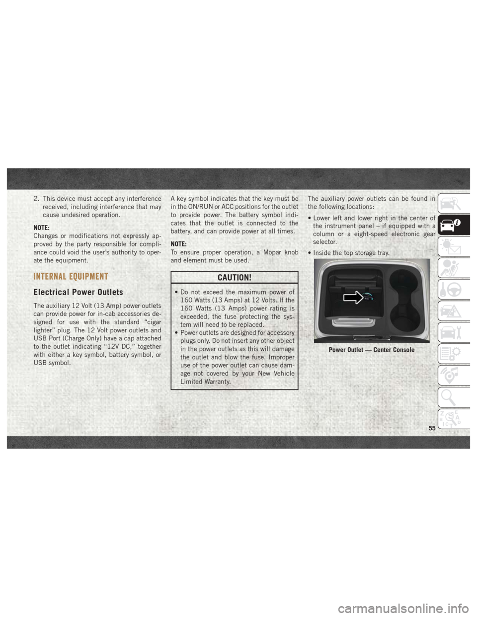
the following locations:
• Lower left and lower right in the center of
the instrument panel – if equipped with a
column or a eight-speed electronic gear
selector.
• Inside the top storage tray.
Power Outlet — Center Console
55
Page 58 of 372
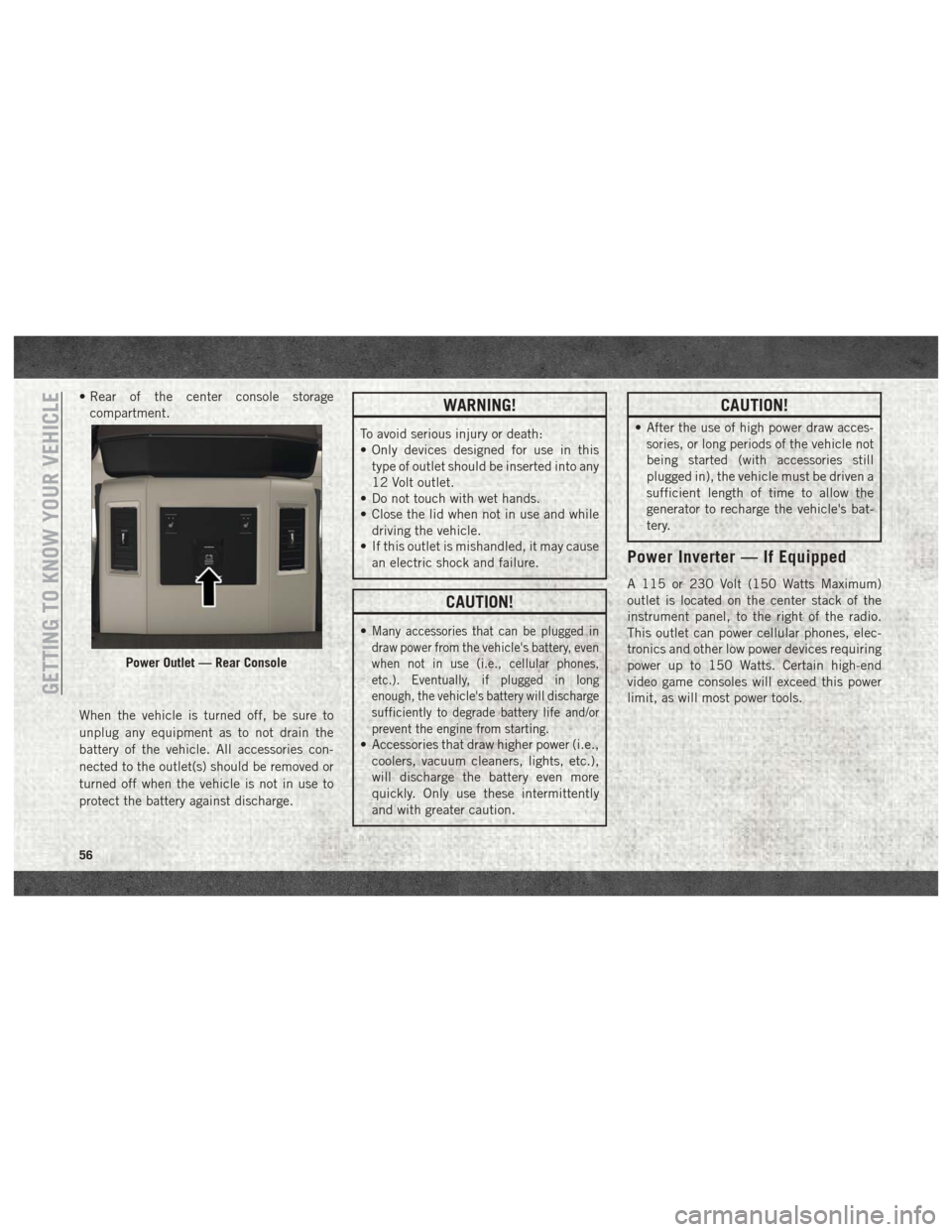
• Rear of the center console storagecompartment.
When the vehicle is turned off, be sure to
unplug any equipment as to not drain the
battery of the vehicle. All accessories con-
nected to the outlet(s) should be removed or
turned off when the vehicle is not in use to
protect the battery against discharge.WARNING!
To avoid serious injury or death:
• Only devices designed for use in this type of outlet should be inserted into any
12 Volt outlet.
• Do not touch with wet hands.
• Close the lid when not in use and while
driving the vehicle.
• If this outlet is mishandled, it may cause
an electric shock and failure.
CAUTION!
•Many accessories that can be plugged in
draw power from the vehicle's battery, even
when not in use (i.e., cellular phones,
etc.). Eventually, if plugged in long
enough, the vehicle's battery will discharge
sufficiently to degrade battery life and/or
prevent the engine from starting.
• Accessories that draw higher power (i.e.,coolers, vacuum cleaners, lights, etc.),
will discharge the battery even more
quickly. Only use these intermittently
and with greater caution.
CAUTION!
• After the use of high power draw acces-sories, or long periods of the vehicle not
being started (with accessories still
plugged in), the vehicle must be driven a
sufficient length of time to allow the
generator to recharge the vehicle's bat-
tery.
Power Inverter — If Equipped
A 115 or 230 Volt (150 Watts Maximum)
outlet is located on the center stack of the
instrument panel, to the right of the radio.
This outlet can power cellular phones, elec-
tronics and other low power devices requiring
power up to 150 Watts. Certain high-end
video game consoles will exceed this power
limit, as will most power tools.
Power Outlet — Rear Console
GETTING TO KNOW YOUR VEHICLE
56