center console Ram 1500 2018 User Guide
[x] Cancel search | Manufacturer: RAM, Model Year: 2018, Model line: 1500, Model: Ram 1500 2018Pages: 372, PDF Size: 7.1 MB
Page 28 of 372
to “Instrument Cluster Display” in “Getting
To Know Your Instrument Panel” in the Own-
er’s Manual for further information.
Rear Heated Seats
On some models, the two outboard seats are
equipped with heated seats. The heated seat
switches for these seats are located on the
rear of the center console.
There are two heated seat switches that allow
the rear passengers to operate the seats in-
dependently. You can choose from HI, LO or
OFF heat settings. Amber indicator lights in
each switch indicate the level of heat in use.
Two indicator lights will illuminate for HI, one
for LO and none for OFF.Push the switch once
to select HI-level heat-
ing. Push the switch a
second time to select
LO-level heating. Push
the switch a third time
to shut the heating el-
ements OFF. NOTE:
• Once a heat setting is selected, heat will be
felt within two to five minutes.
• The engine must be running for the heated seats to operate.
When the HI-level setting is selected, the
heater will provide a boosted heat level dur-
ing the first four minutes of operation. Then,
the heat output will drop to the normal HI-
level. If the HI-level setting is selected, the
system will automatically switch to LO-level
after approximately 60 minutes of continu-
ous operation. At that time, the number of
illuminated LEDs changes from two to one,
indicating the change. The LO-level setting
will turn OFF automatically after approxi-
mately 45 minutes.
Ventilated Seats — If Equipped
Located in the seat cushion are small fans
that draw the air from the passenger compart-
ment and move air through fine perforations
in the seat cover to help keep the driver and
front passenger cooler in higher ambient
temperatures. The fans operate at two
speeds, HI and LO. The front ventilated seats control buttons are
located on the center instrument panel below
the climate controls.
If your vehicle is equipped with a touch-
screen, the front ventilated seats control but-
tons are also located within the climate or
controls screen of the touchscreen.
• Press the ventilated seat button
once to
choose HI.
• Press the ventilated seat button
a
second time to choose LO.
• Press the ventilated seat button
a third
time to turn the ventilated seat OFF.
NOTE:
The engine must be running for the venti-
lated seats to operate.
Vehicles Equipped With Remote Start
On models that are equipped with remote
start, the ventilated seats can be pro-
grammed to come on during a remote start.
GETTING TO KNOW YOUR VEHICLE
26
Page 53 of 372
2. Reach into the opening beneath the cen-ter of the hood and push the safety latch
lever to the left to release it, before raising
the hood.
To Close The Hood
Lower the hood to approximately 12 inches
(30 cm) from the engine compartment and
drop it. Make sure that the hood is completely
closed.
WARNING!
Be sure the hood is fully latched before
driving your vehicle. If the hood is not fully
latched, it could open when the vehicle is
in motion and block your vision. Failure to
follow this warning could result in serious
injury or death.
CAUTION!
To prevent possible damage, do not slam
the hood to close it. Use a firm downward
push at the front center of the hood to
ensure that both latches engage.
UNIVERSAL GARAGE DOOR OPENER
(HOMELINK)
• HomeLink replaces up to three hand-heldtransmitters that operate devices such as
garage door openers, motorized gates,
lighting or home security systems. The
HomeLink unit is powered by your vehicles
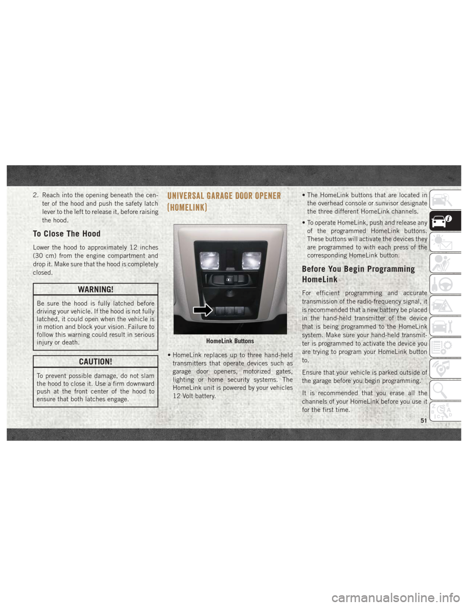
12 Volt battery. • The HomeLink buttons that are located in
the overhead console or sunvisor designate
the three different HomeLink channels.
• To operate HomeLink, push and release any of the programmed HomeLink buttons.
These buttons will activate the devices they
are programmed to with each press of the
corresponding HomeLink button.
Before You Begin Programming
HomeLink
For efficient programming and accurate
transmission of the radio-frequency signal, it
is recommended that a new battery be placed
in the hand-held transmitter of the device
that is being programmed to the HomeLink
system. Make sure your hand-held transmit-
ter is programmed to activate the device you
are trying to program your HomeLink button
to.
Ensure that your vehicle is parked outside of
the garage before you begin programming.
It is recommended that you erase all the
channels of your HomeLink before you use it
for the first time.
HomeLink Buttons
51
Page 57 of 372
2. This device must accept any interferencereceived, including interference that may
cause undesired operation.
NOTE:
Changes or modifications not expressly ap-
proved by the party responsible for compli-
ance could void the user’s authority to oper-
ate the equipment.
INTERNAL EQUIPMENT
Electrical Power Outlets
The auxiliary 12 Volt (13 Amp) power outlets
can provide power for in-cab accessories de-
signed for use with the standard “cigar
lighter” plug. The 12 Volt power outlets and
USB Port (Charge Only) have a cap attached
to the outlet indicating “12V DC,” together
with either a key symbol, battery symbol, or
USB symbol. A key symbol indicates that the key must be
in the ON/RUN or ACC positions for the outlet
to provide power. The battery symbol indi-
cates that the outlet is connected to the
battery, and can provide power at all times.
NOTE:
To ensure proper operation, a Mopar knob
and element must be used.
CAUTION!
• Do not exceed the maximum power of
160 Watts (13 Amps) at 12 Volts. If the
160 Watts (13 Amps) power rating is
exceeded, the fuse protecting the sys-
tem will need to be replaced.
• Power outlets are designed for accessory
plugs only. Do not insert any other object
in the power outlets as this will damage
the outlet and blow the fuse. Improper
use of the power outlet can cause dam-
age not covered by your New Vehicle
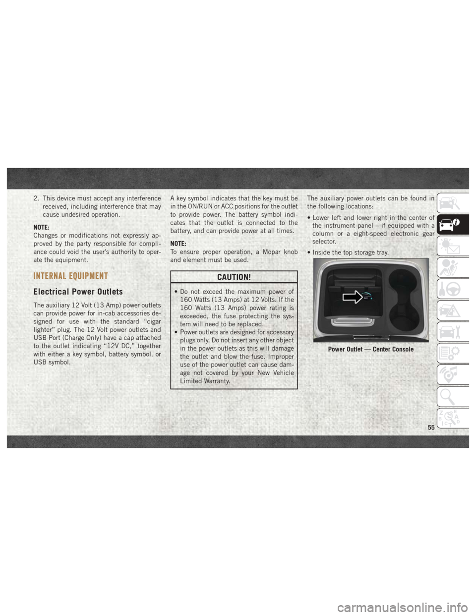
Limited Warranty. The auxiliary power outlets can be found in
the following locations:
• Lower left and lower right in the center of
the instrument panel – if equipped with a
column or a eight-speed electronic gear
selector.
• Inside the top storage tray.
Power Outlet — Center Console
55
Page 58 of 372
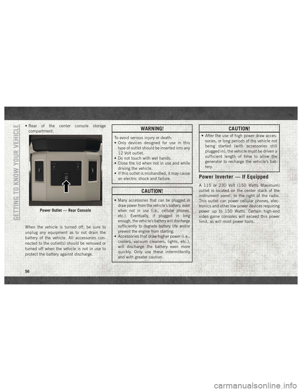
• Rear of the center console storagecompartment.
When the vehicle is turned off, be sure to
unplug any equipment as to not drain the
battery of the vehicle. All accessories con-
nected to the outlet(s) should be removed or
turned off when the vehicle is not in use to
protect the battery against discharge.WARNING!
To avoid serious injury or death:
• Only devices designed for use in this type of outlet should be inserted into any
12 Volt outlet.
• Do not touch with wet hands.
• Close the lid when not in use and while
driving the vehicle.
• If this outlet is mishandled, it may cause
an electric shock and failure.
CAUTION!
•Many accessories that can be plugged in
draw power from the vehicle's battery, even
when not in use (i.e., cellular phones,
etc.). Eventually, if plugged in long
enough, the vehicle's battery will discharge
sufficiently to degrade battery life and/or
prevent the engine from starting.
• Accessories that draw higher power (i.e.,coolers, vacuum cleaners, lights, etc.),
will discharge the battery even more
quickly. Only use these intermittently
and with greater caution.
CAUTION!
• After the use of high power draw acces-sories, or long periods of the vehicle not
being started (with accessories still
plugged in), the vehicle must be driven a
sufficient length of time to allow the
generator to recharge the vehicle's bat-
tery.
Power Inverter — If Equipped
A 115 or 230 Volt (150 Watts Maximum)
outlet is located on the center stack of the
instrument panel, to the right of the radio.
This outlet can power cellular phones, elec-
tronics and other low power devices requiring
power up to 150 Watts. Certain high-end
video game consoles will exceed this power
limit, as will most power tools.
Power Outlet — Rear Console
GETTING TO KNOW YOUR VEHICLE
56
Page 203 of 372

IN CASE OF EMERGENCY
HAZARD WARNING FLASHERS.....202
BULB REPLACEMENT ...........202
Replacement Bulbs.............202
FUSES.................... .203
Power Distribution Center.........203
JACKING AND TIRE CHANGING ......208
Jack Location................208
Removal Of Jack And Tools ........208
Removing The Spare Tire ..........209
Preparations For Jacking ..........210
Jacking Instructions ............211 To Stow The Flat Or Spare
........214
Reinstalling The Jack And Tools .....215
Hub Caps/Wheel Covers —
If Equipped .................217
JUMP STARTING ..............218
Preparations For Jump Start ........218
Jump Starting Procedure ..........219
IF YOUR ENGINE OVERHEATS ......220
GEAR SELECTOR OVERRIDE —
6-SPEED TRANSMISSION .........221
Column Gear Selector — If Equipped . .221
Center Console Gear Selector — If
Equipped...................222
MANUAL PARK RELEASE — 8 SPEED
TRANSMISSION ..............222
FREEING A STUCK VEHICLE .......224
TOWING A DISABLED VEHICLE .....225
Two-Wheel Drive Models..........226
Four-Wheel Drive Models ..........226
Emergency Tow Hooks — If Equipped . .227
ENHANCED ACCIDENT RESPONSE
SYSTEM (EARS) ...............227
EVENT DATA RECORDER (EDR) ......227
IN CASE OF EMERGENCY
201
Page 204 of 372
HAZARD WARNING FLASHERS
The Hazard Warning flasher switch is located
on the upper switch bank just below the
radio.
Push the switch to turn on the Hazard Warn-
ing flasher. When the switch is activated, all
directional turn signals will flash on and off to
warn oncoming traffic of an emergency. Push
the switch a second time to turn off the
Hazard Warning flashers.
This is an emergency warning system and it
should not be used when the vehicle is in
motion. Use it when your vehicle is disabled
and it is creating a safety hazard for other
motorists.
When you must leave the vehicle to seek
assistance, the Hazard Warning flashers will
continue to operate even though the ignition
is placed in the OFF position.
NOTE:
With extended use the Hazard Warning flash-
ers may wear down your battery.
BULB REPLACEMENT
Replacement Bulbs
All of the inside bulbs are brass or glass-
wedge base. Aluminum base bulbs are not
approved.
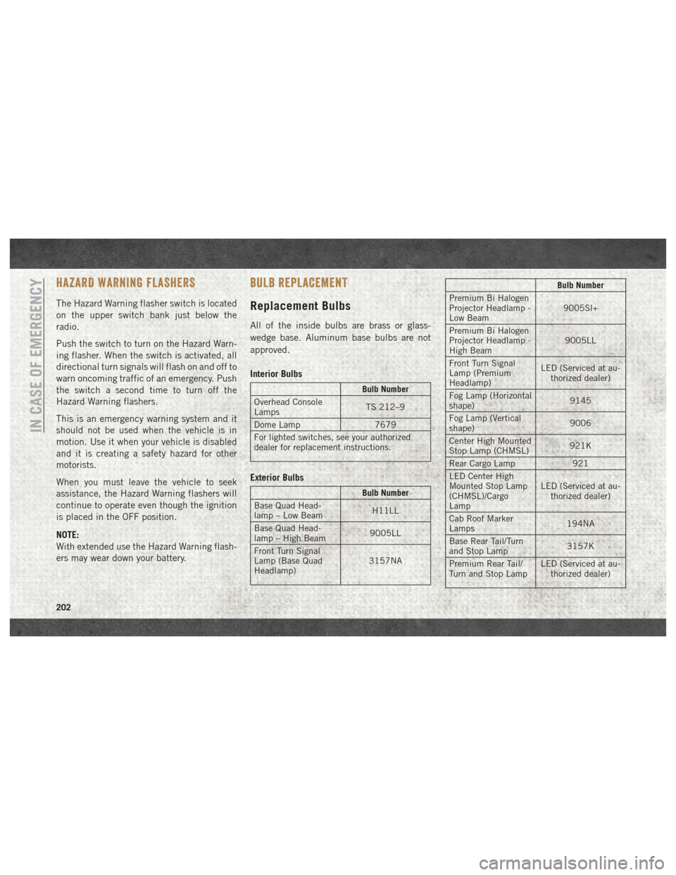
Interior Bulbs
Bulb Number
Overhead Console
Lamps TS 212–9
Dome Lamp 7679
For lighted switches, see your authorized
dealer for replacement instructions.
Exterior Bulbs
Bulb Number
Base Quad Head-
lamp – Low Beam H11LL
Base Quad Head-
lamp – High Beam 9005LL
Front Turn Signal
Lamp (Base Quad
Headlamp) 3157NA
Bulb Number
Premium Bi Halogen
Projector Headlamp -
Low Beam 9005Sl+
Premium Bi Halogen
Projector Headlamp -
High Beam 9005LL
Front Turn Signal
Lamp (Premium
Headlamp) LED (Serviced at au-
thorized dealer)
Fog Lamp (Horizontal
shape) 9145
Fog Lamp (Vertical
shape) 9006
Center High Mounted
Stop Lamp (CHMSL) 921K
Rear Cargo Lamp 921
LED Center High
Mounted Stop Lamp
(CHMSL)/Cargo
Lamp LED (Serviced at au-
thorized dealer)
Cab Roof Marker
Lamps 194NA
Base Rear Tail/Turn
and Stop Lamp 3157K
Premium Rear Tail/
Turn and Stop Lamp LED (Serviced at au-
thorized dealer)
IN CASE OF EMERGENCY
202
Page 210 of 372
CavityCartridge Fuse Micro Fuse Description
F100 –10 Amp Red Upfitters – If Equipped
F101 –15 Amp Blue Electrochromatic Mirror / Smart High Beams – If
Equipped
F104 –20 Amp Yellow Power Outlets (Instrument Panel / Center Console)
CAUTION!
• When installing the power distribution
center cover, it is important to ensure
the cover is properly positioned and fully
latched. Failure to do so may allow water
to get into the power distribution center
and possibly result in an electrical sys-
tem failure.
• When replacing a blown fuse, it is impor-
tant to use only a fuse having the correct
amperage rating. The use of a fuse with
a rating other than indicated may result
in a dangerous electrical system over-
load. If a properly rated fuse continues
to blow, it indicates a problem in the
circuit that must be corrected.
JACKING AND TIRE CHANGING
Jack Location
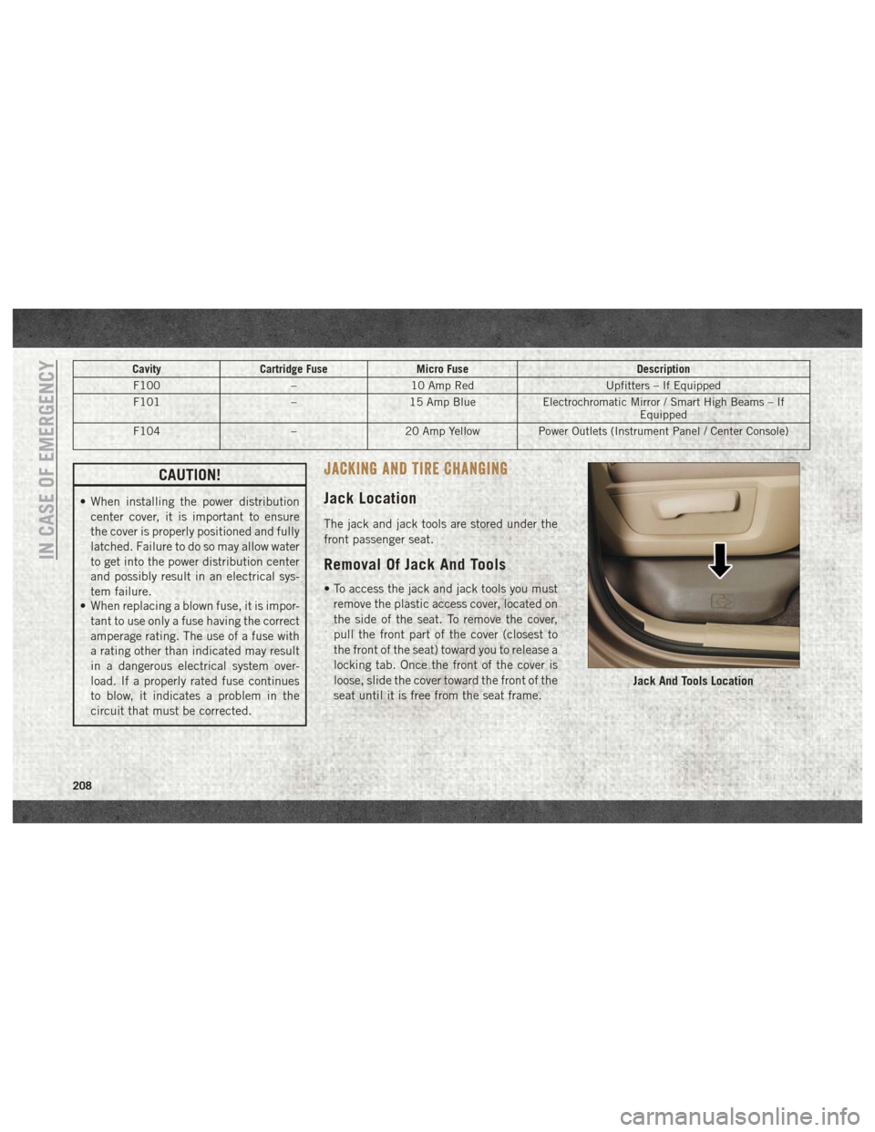
The jack and jack tools are stored under the
front passenger seat.
Removal Of Jack And Tools
• To access the jack and jack tools you must
remove the plastic access cover, located on
the side of the seat. To remove the cover,
pull the front part of the cover (closest to
the front of the seat) toward you to release a
locking tab. Once the front of the cover is
loose, slide the cover toward the front of the
seat until it is free from the seat frame.
Jack And Tools Location
IN CASE OF EMERGENCY
208
Page 224 of 372

Center Console Gear Selector —
If Equipped
1. Turn the engine OFF.
2. Firmly apply the parking brake.
3. Using a small screwdriver or similar tool,remove the gear selector override access
cover (located to the right of the gear
selector).
4. Press and maintain firm pressure on the brake pedal.
5. Insert the screwdriver or similar tool into the access hole, and push and hold the
override release lever down. 6. Move the gear selector to the NEUTRALposition.
7. The vehicle may then be started in NEUTRAL.
8. Reinstall the gear selector override access cover.
MANUAL PARK RELEASE — 8 SPEED
TRANSMISSION
WARNING!
Always secure your vehicle by fully apply-
ing the parking brake before activating the
Manual Park Release. In addition, you
should be seated in the driver’s seat with
your foot firmly on the brake pedal when
activating the Manual Park Release. Acti-
vating the Manual Park Release will allow
your vehicle to roll away if it is not secured
by the parking brake, or by proper connec-
tion to a tow vehicle. Activating the
Manual Park Release on an unsecured
vehicle could lead to serious injury or
death for those in or around the vehicle.
In order to push or tow the vehicle in cases
where the transmission will not shift out of
PARK (such as a dead battery), a Manual
Park Release is available.
Gear Selector Override Access Cover
IN CASE OF EMERGENCY
222
Page 295 of 372
Clock Setting
1. Push the Menu button at the bottom ofthe radio, and push the Enter/Browse but-
ton for System Settings. Next, select the
Time and Format setting and then select
Set Time by pushing the Enter/Browse
button.
2. Adjust the hours or minutes by turning the Tune/Scroll knob, then pushing the Enter/
Browse button to move to the next entry.
You can also select 12hr or 24hr format by
turning the Tune/Scroll knob, then push-
ing the Enter/Browse button on the de-
sired selection.
3. Once the time is set, press the “Ok” button to exit the time screen.
Audio Setting
• Push the AUDIO button on the radio face-plate.
• The Audio Menu shows the following op- tions for you to customize your audio
settings. Treble, Mid, Bass, Fade, Balance, Speed Ad-
justed Volume, Loudness and AUX Offset
• Select the desired setting to adjust, then
push the ENTER/BROWSE button. Turn the
TUNE/SCROLL knob to adjust the setting +
or - . Push the “Back” button when done.
Radio Operation
Seek Up/Down Buttons
• Push the up or down button to seek throughradio stations in AM, FM or SXM bands.
• Hold either button to bypass stations with- out stopping.
Store Radio Presets Manually
The presets are available for all Radio Modes,
and are activated by pushing any of the six
preset buttons. The Radio stores up to
18 presets in each of the Radio modes. Push
the A-B-C button on the faceplate to select
the A, B, or C preset list.
To store a radio preset manually, follow the
steps below:
1. Tune to the desired station. 2. Push and hold the desired numbered but-
ton for more than two seconds, or until you
hear a confirmation beep.
Disc Operation — If Equipped
Your vehicle may have a remote CD player
located in the lower center console storage
bin, or in the lower center bench seat bin.
• CD/Disc Mode is entered by either insertinga CD/Disc or by pushing the MEDIA button
located on the side of the display. Once in
Media Mode, select “Disc.”
Gently insert one CD into the CD player with
the CD label facing as indicated on the illus-
tration located on the Disc player.
Seek Up/Down Buttons
• Push to seek through CD tracks.
• Hold either button to bypass tracks without stopping.
293
Page 298 of 372
Clock Setting
1. Push the Menu button at the bottom ofthe radio, and push the Enter/Browse but-
ton for System Settings. Next, select the
Time and Format setting and then select
Set Time by pushing the Enter/Browse
button.
2. Adjust the hours or minutes by turning the Tune/Scroll knob, then pushing the Enter/
Browse button to move to the next entry.
You can also select 12hr or 24hr format
by turning the Tune/Scroll knob, then
pushing the Enter/Browse button on the
desired selection.
3. Once the time is set, press the “Ok” button to exit the time screen.
Audio Setting
• Push the AUDIO button on the radio face-plate.
• The Audio Menu shows the following op- tions for you to customize your audio
settings. Treble, Mid, Bass, Fade, Balance, Speed Ad-
justed Volume, Loudness and AUX Offset
• Select the desired setting to adjust, then
push the ENTER/BROWSE button. Turn the
TUNE/SCROLL knob to adjust the setting +
or - . Push the “Back” button when done.
Radio Operation
Seek Up/Down Buttons
• Push the up or down button to seek throughradio stations in AM, FM or SXM bands.
• Hold either button to bypass stations with- out stopping.
Store Radio Presets Manually
The presets are available for all Radio Modes,
and are activated by pushing any of the six
preset buttons. The Radio stores up to
18 presets in each of the Radio modes. Push
the A-B-C button on the faceplate to select
the A, B, or C preset list. To store a radio preset manually, follow the
steps below:
1. Tune to the desired station.
2. Push and hold the desired numbered but-
ton for more than two seconds, or until
you hear a confirmation beep.
Disc Operation — If Equipped
Your vehicle may have a remote CD player
located in the lower center console storage
bin, or in the lower center bench seat bin.
• CD/Disc Mode is entered by either insertinga CD/Disc or by pushing the MEDIA button
located on the side of the display. Once in
Media Mode, select “Disc.”
Gently insert one CD into the CD player with
the CD label facing as indicated on the illus-
tration located on the Disc player.
Seek Up/Down Buttons
• Push to seek through CD tracks.
• Hold either button to bypass tracks without stopping.
MULTIMEDIA
296