egr Ram 1500 2020 User Guide
[x] Cancel search | Manufacturer: RAM, Model Year: 2020, Model line: 1500, Model: Ram 1500 2020Pages: 674, PDF Size: 32.69 MB
Page 221 of 674
SAFETY 219
The vehicle must be moving above 6 mph (10 km/h) to
activate the feature. Once the trailer has been detected, the
system will default to the maximum blind spot zone until
the length has been verified. You will see “Auto” in the
instrument panel cluster .
• Max Mode — When “Max Mode” is selected, the system
will default to the maximum blind spot zone regardless of
what size trailer is attached
NOTE:
Selected setting is stored when the ignition is cycled OFF. To
change this setting, it must be selected through the Uconnect
Settings. Refer to “Uconnect Settings” in “Multimedia” for
further information.
Trailer Length Detection
Once the trailer presence has been established. The trailer
length will be established (by making a 90 degree turn) and
then the trailer length category (example 10-20 ft (3 m to
6 m)) will be displayed. This can take up to 30 seconds after
completing the turn. NOTE:
During the same ignition cycle, if the vehicle is at a standstill
for a minimum of 90 seconds, a new “trailer detection
request” is enabled by the system once the vehicle resumes
motion.
Maximum length supported by the Trailer Merge Assist
feature is 39.5 ft (12 m). Trailer length is considered the
forward most portion of the trailer hitch to the rearward
most portion of the body, bumper, or ramp of the trailer.
Maximum width supported by the Trailer Merge Assist
feature is 8.5 ft (2.59 m). Trailer width is measured at the
widest portion of the trailer and may include wheels, tires,
finders, or rails.
NOTE:
Fifth wheel or gooseneck trailers are not supported by
Trailer Merge Assist.
4
2020_DT_1500_OM_US.book Page 219
Page 243 of 674

SAFETY 241
Lap/Shoulder Belt Untwisting Procedure
Use the following procedure to untwist a twisted lap/
shoulder belt.
1. Position the latch plate as close as possible to the anchorpoint.
2. At about 6 to 12 inches (15 to 30 cm) above the latch plate, grasp and twist the seat belt webbing 180 degrees to
create a fold that begins immediately above the latch
plate.
3. Slide the latch plate upward over the folded webbing. The folded webbing must enter the slot at the top of the
latch plate.
4. Continue to slide the latch plate up until it clears the folded webbing and the seat belt is no longer twisted.
Adjustable Upper Shoulder Belt Anchorage
In the driver and outboard front passenger seats, the top of
the shoulder belt can be adjusted upward or downward to
position the seat belt away from your neck. Push or squeeze
the anchorage button to release the anchorage, and move it
up or down to the position that serves you best. Adjustable Anchorage
As a guide, if you are shorter than average, you will prefer
the shoulder belt anchorage in a lower position, and if you
are taller than average, you will prefer the shoulder belt
anchorage in a higher position. After you release the
anchorage button, try to move it up or down to make sure
that it is locked in position.
4
2020_DT_1500_OM_US.book Page 241
Page 310 of 674

308 STARTING AND OPERATING
When frequent transmission shifting occurs (such as when
operating the vehicle under heavy loading conditions, in
hilly terrain, traveling into strong head winds, or while
towing a heavy trailer), select TOW/HAUL mode or use the
Electronic Range Select (ERS) shift control (refer to "Elec-
tronic Range Select (ERS) Operation" in this section for
further information) to select a lower gear range. Under
these conditions, using a lower gear range will improve
performance and extend transmission life by reducing exces -
sive shifting and heat buildup.
During extremely cold temperatures (-22°F [-30°C] or
below), transmission operation may be modified depending
on engine and transmission temperature as well as vehicle
speed. Normal operation will resume once the transmission
temperature has risen to a suitable level.
Transmission Limp Home Mode
Transmission function is monitored electronically for
abnormal conditions. If a condition is detected that could
result in transmission damage, Transmission Limp Home
Mode is activated. In this mode, the transmission may
operate only in certain gears, or may not shift at all. Vehicle
performance may be severely degraded and the engine may
stall. In some situations, the transmission may not re-engage
if the engine is turned off and restarted. The Malfunction Indicator Light (MIL) may be illuminated. A message in the
instrument cluster will inform the driver of the more serious
conditions, and indicate what actions may be necessary.
In the event of a momentary problem, the transmission can
be reset to regain all forward gears by performing the
following steps:
NOTE:
In cases where the instrument cluster message indicates the
transmission may not re-engage after engine shutdown,
perform this procedure only in a desired location (prefer
-
ably, at an authorized dealer).
1. Stop the vehicle.
2. Shift the transmission into PARK, if possible. If not, shift the transmission to NEUTRAL.
3. Push and hold the ignition switch until the engine turns OFF.
4. Wait approximately 30 seconds.
5. Restart the engine.
6. Shift into the desired gear range. If the problem is no longer detected, the transmission will return to normal
operation.
2020_DT_1500_OM_US.book Page 308
Page 356 of 674
354 STARTING AND OPERATING
NOTE:
• If the “ACC/FCW Unavailable Wipe Front Radar Sensor”message occurs frequently (e.g. more than once on every
trip) without any snow, rain, mud, or other obstruction,
have the radar sensor realigned at your authorized dealer.
• Installing a snow plow, front-end protector, an after -
market grille or modifying the grille is not recommended.
Doing so may block the sensor and inhibit ACC/FCW
operation.
“Clean Front Windshield” Warning
The “ACC/FCW Limited Functionality Clean Front Wind -
shield” warning will display and also a chime will indicate
when conditions temporarily limit system performance. This
most often occurs at times of poor visibility, such as in snow
or heavy rain and fog. The ACC system may also become
temporarily blinded due to obstructions, such as mud, dirt,
or ice on windshield, driving directly into the sun and fog on
the inside of glass. In these cases, the instrument cluster
display will show “ACC/FCW Limited Functionality Clean
Front Windshield” and the system will have degraded
performance.
The “ACC/FCW Limited Functionality Clean Front Wind -
shield” message can sometimes be displayed while driving in adverse weather conditions. The ACC/FCW system will
recover after the vehicle has left these areas. Under rare
conditions, when the camera is not tracking any vehicles or
objects in its path this warning may temporarily occur.
If weather conditions are not a factor, the driver should
examine the windshield and the camera located on the back
side of the inside rear view mirror. They may require
cleaning or removal of an obstruction.
When the condition that created limited functionality is no
longer present, the system will return to full functionality.
NOTE:
If the “ACC/FCW Limited Functionality Clean Front Wind
-
shield” message occurs frequently (e.g. more than once on
every trip) without any snow, rain, mud, or other obstruc -
tion, have the windshield and forward facing camera
inspected at your authorized dealer.
Service ACC/FCW Warning
If the system turns off, and the instrument cluster displays
“ACC/FCW Unavailable Service Required” or “Cruise/
FCW Unavailable Service Required”, there may be an
internal system fault or a temporary malfunction that limits
ACC functionality. Although the vehicle is still drivable
under normal conditions, ACC will be temporarily unavail -
2020_DT_1500_OM_US.book Page 354
Page 357 of 674
STARTING AND OPERATING 355
able. If this occurs, try activating ACC again later, following
an ignition cycle. If the problem persists, see your authorized
dealer.
Precautions While Driving With ACC
In certain driving situations, ACC may have detection issues.
In these cases, ACC may brake late or unexpectedly. The
driver needs to stay alert and may need to intervene.
NOTE:
• Aftermarket add-ons such as snow plows, lift kits, andbrush/grille bars can hinder module performance. Ensure
the radar/camera has no obstructions in the field of view.
• Height modifications can limit module performance and functionality.
• Do not put stickers or easy passes over the camera/radar field of view.
• Any modifications to the vehicle that may obstruct the field of view of the radar/camera are not recommended.
Cleaning Instructions
Dust and dirt can accumulate on the cover and block the
camera lens. Clean the camera lens with a soft microfiber
cloth, being careful not to damage or scratch the module. Towing A Trailer
ACC while towing a trailer is recommended only with an
Integrated Trailer Brake Controller. Aftermarket trailer
brake controllers will not activate the trailer brakes when
ACC is braking.
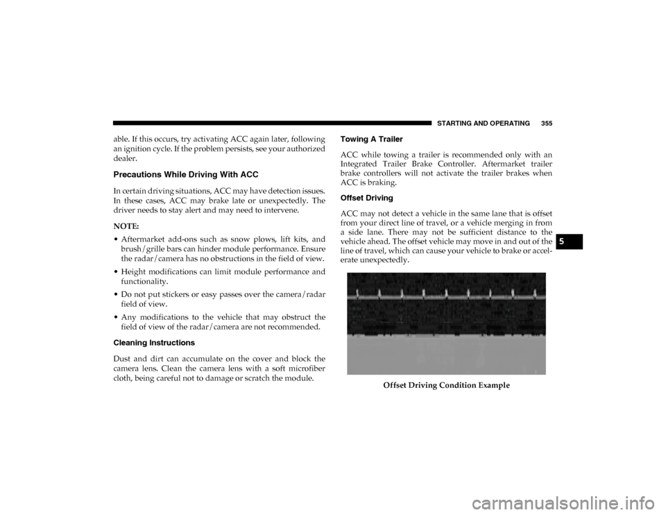
Offset Driving
ACC may not detect a vehicle in the same lane that is offset
from your direct line of travel, or a vehicle merging in from
a side lane. There may not be sufficient distance to the
vehicle ahead. The offset vehicle may move in and out of the
line of travel, which can cause your vehicle to brake or accel
-
erate unexpectedly.
Offset Driving Condition Example
5
2020_DT_1500_OM_US.book Page 355
Page 418 of 674
416 STARTING AND OPERATING
Integrated Trailer Brake Module — If Equipped
Your vehicle may have an Integrated Trailer Brake Module
(ITBM) for Electric and Electric Over Hydraulic (EOH) trailer
brakes.
NOTE:
This module has been designed and verified with electric
trailer brakes and new electric over hydraulic systems. Some
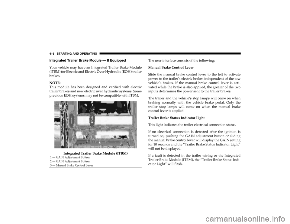
previous EOH systems may not be compatible with ITBM.Integrated Trailer Brake Module (ITBM) The user interface consists of the following:
Manual Brake Control Lever
Slide the manual brake control lever to the left to activate
power to the trailer's electric brakes independent of the tow
vehicle's brakes. If the manual brake control lever is acti
-
vated while the brake is also applied, the greater of the two
inputs determines the power sent to the trailer brakes.
The trailer and the vehicle’s stop lamps will come on when
braking normally with the vehicle brake pedal. Only the
trailer stop lamps will come on when the manual brake
control lever is applied.
Trailer Brake Status Indicator Light
This light indicates the trailer electrical connection status.
If no electrical connection is detected after the ignition is
turned on, pushing the GAIN adjustment button or sliding
the manual brake control lever will display the GAIN setting
for 10 seconds and the “Trailer Brake Status Indicator Light”
will not be displayed.
If a fault is detected in the trailer wiring or the Integrated
Trailer Brake Module (ITBM), the “Trailer Brake Status Indi -
cator Light” will flash.
1 — GAIN Adjustment Button
2 — GAIN Adjustment Button
3 — Manual Brake Control Lever
2020_DT_1500_OM_US.book Page 416
Page 452 of 674
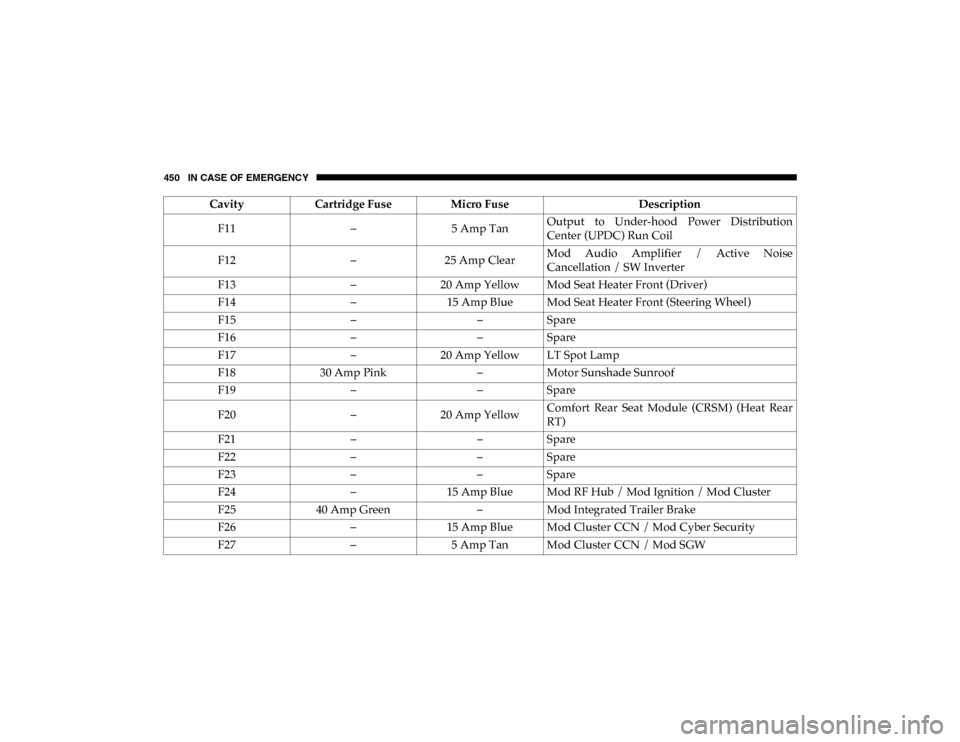
450 IN CASE OF EMERGENCY
F11–5 Amp TanOutput to Under-hood Power Distribution
Center (UPDC) Run Coil
F12 –25 Amp Clear Mod Audio Amplifier / Active Noise
Cancellation / SW Inverter
F13 –20 Amp Yellow Mod Seat Heater Front (Driver)
F14 –15 Amp Blue Mod Seat Heater Front (Steering Wheel)
F15 ––Spare
F16 ––Spare
F17 –20 Amp Yellow LT Spot Lamp
F18 30 Amp Pink –Motor Sunshade Sunroof
F19 ––Spare
F20 –20 Amp Yellow Comfort Rear Seat Module (CRSM) (Heat Rear
RT)
F21 ––Spare
F22 ––Spare
F23 ––Spare
F24 –15 Amp Blue Mod RF Hub / Mod Ignition / Mod Cluster
F25 40 Amp Green –Mod Integrated Trailer Brake
F26 –15 Amp Blue Mod Cluster CCN / Mod Cyber Security
F27 –5 Amp Tan Mod Cluster CCN / Mod SGW
Cavity
Cartridge Fuse Micro Fuse Description
2020_DT_1500_OM_US.book Page 450
Page 477 of 674
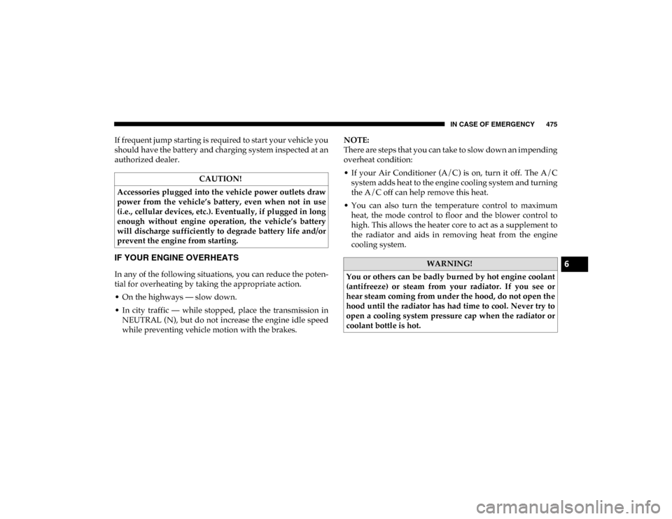
IN CASE OF EMERGENCY 475
If frequent jump starting is required to start your vehicle you
should have the battery and charging system inspected at an
authorized dealer.
IF YOUR ENGINE OVERHEATS
In any of the following situations, you can reduce the poten-
tial for overheating by taking the appropriate action.
• On the highways — slow down.
• In city traffic — while stopped, place the transmission in NEUTRAL (N), but do not increase the engine idle speed
while preventing vehicle motion with the brakes. NOTE:
There are steps that you can take to slow down an impending
overheat condition:
• If your Air Conditioner (A/C) is on, turn it off. The A/C
system adds heat to the engine cooling system and turning
the A/C off can help remove this heat.
• You can also turn the temperature control to maximum heat, the mode control to floor and the blower control to
high. This allows the heater core to act as a supplement to
the radiator and aids in removing heat from the engine
cooling system.
CAUTION!
Accessories plugged into the vehicle power outlets draw
power from the vehicle’s battery, even when not in use
(i.e., cellular devices, etc.). Eventually, if plugged in long
enough without engine operation, the vehicle’s battery
will discharge sufficiently to degrade battery life and/or
prevent the engine from starting.
WARNING!
You or others can be badly burned by hot engine coolant
(antifreeze) or steam from your radiator. If you see or
hear steam coming from under the hood, do not open the
hood until the radiator has had time to cool. Never try to
open a cooling system pressure cap when the radiator or
coolant bottle is hot.6
2020_DT_1500_OM_US.book Page 475
Page 640 of 674

638 MULTIMEDIA
Climate
Too hot? Too cold? Adjust vehicle temperatures hands-free
and keep everyone comfortable while you keep moving
ahead. (If vehicle is equipped with climate control.)
Push the VR button . After the beep, say one of the
following commands:
• “Set driver temperature to 70 degrees ”
• “Set passenger temperature to 70 degrees ”
TIP:
Voice Command for Climate may only be used to adjust the
interior temperature of your vehicle. Voice Command will
not work to adjust the heated seats or steering wheel if
equipped. Uconnect 4/4C/4C NAV With 8.4-inch Display Climate
2020_DT_1500_OM_US.book Page 638
Page 664 of 674

662
Gross Vehicle Weight Rating ................................................ 407
GuideBody Builders ........................................................................ 14
GVWR ....................................................................................... 405 H
Hazard Driving Through Flowing, Rising, Or Shallow
Standing Water .................................................................... 427
Hazard Warning Flashers ...................................................... 431
Head Restraints ......................................................................... 54
Head Rests ................................................................................. 54
Headlights ................................................................................ 438 Cleaning................................................................................ 540
High Beam.............................................................................. 68
High Beam/Low Beam Select Switch ................................ 68
Lights On Reminder ............................................................. 71
Passing .................................................................................... 69
Switch...................................................................................... 66
Heated Mirrors .......................................................................... 65
Heater, Engine Block .............................................................. 296
High Beam/Low Beam Select (Dimmer) Switch ................. 68
Hill Descent Control ............................................................... 205
Hill Descent Control Indicator .............................................. 205
Hill Start Assist........................................................................ 207
Hitches Trailer Towing ..................................................................... 411 Hoisting ....................................................................................516
HomeLink (Garage Door Opener) ........................................109
Hood Prop ................................................................................105
Hood Release ...........................................................................105
I
Ignition........................................................................................25 Switch ......................................................................................25
Illuminated Entry ......................................................................75
In Vehicle Help Vehicle User Guide ...............................................................16
Inside Rearview Mirror ..............................................59, 60, 431 Instrument Cluster Descriptions .........................................................................193
Display ..................................................................................166
Instrument Panel Lens Cleaning...........................................545
Integrated Trailer Brake Control...........................................416
Interior Appearance Care ......................................................543
Interior Lights ............................................................................73 Intermittent Wipers (Delay Wipers) .......................................76
Introduction ...............................................................................13
Inverter Outlet (115V).............................................................131
iPod/USB/MP3 Control ........................................................623 J
Jack Location ............................................................................454
Jump Starting ...........................................................................472
2020_DT_1500_OM_US.book Page 662