steering Ram 1500 2020 User Guide
[x] Cancel search | Manufacturer: RAM, Model Year: 2020, Model line: 1500, Model: Ram 1500 2020Pages: 674, PDF Size: 32.69 MB
Page 108 of 674
106 GETTING TO KNOW YOUR VEHICLE
1. Pull the hood release lever located below the steeringwheel at the base of the instrument panel.
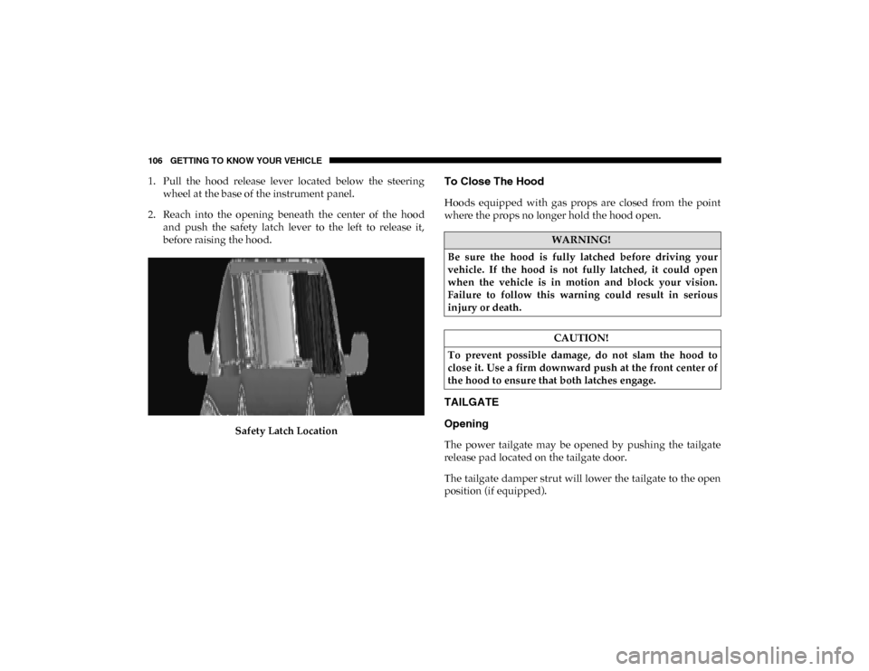
2. Reach into the opening beneath the center of the hood and push the safety latch lever to the left to release it,
before raising the hood.
Safety Latch LocationTo Close The Hood
Hoods equipped with gas props are closed from the point
where the props no longer hold the hood open.
TAILGATE
Opening
The power tailgate may be opened by pushing the tailgate
release pad located on the tailgate door.
The tailgate damper strut will lower the tailgate to the open
position (if equipped).
WARNING!
Be sure the hood is fully latched before driving your
vehicle. If the hood is not fully latched, it could open
when the vehicle is in motion and block your vision.
Failure to follow this warning could result in serious
injury or death.
CAUTION!
To prevent possible damage, do not slam the hood to
close it. Use a firm downward push at the front center of
the hood to ensure that both latches engage.
2020_DT_1500_OM_US.book Page 106
Page 134 of 674
132 GETTING TO KNOW YOUR VEHICLE
NOTE:
400 Watts is the maximum for the inverter, not each outlet. If
three outlets are in use, 400 Watts is shared amongst the
devices plugged in.
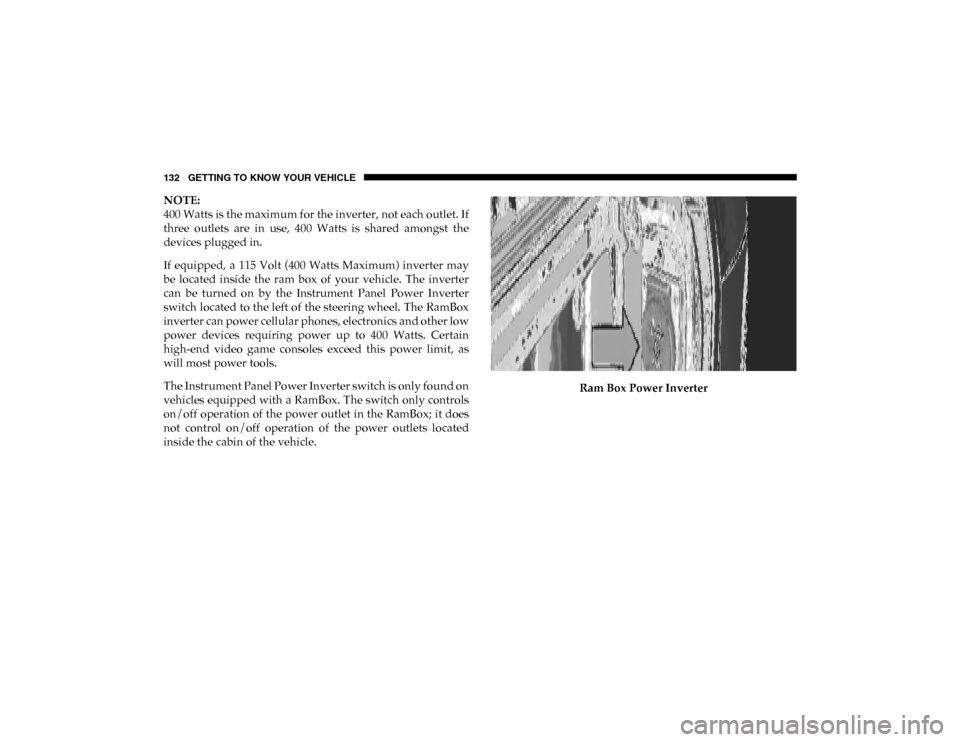
If equipped, a 115 Volt (400 Watts Maximum) inverter may
be located inside the ram box of your vehicle. The inverter
can be turned on by the Instrument Panel Power Inverter
switch located to the left of the steering wheel. The RamBox
inverter can power cellular phones, electronics and other low
power devices requiring power up to 400 Watts. Certain
high-end video game consoles exceed this power limit, as
will most power tools.
The Instrument Panel Power Inverter switch is only found on
vehicles equipped with a RamBox. The switch only controls
on/off operation of the power outlet in the RamBox; it does
not control on/off operation of the power outlets located
inside the cabin of the vehicle.Ram Box Power Inverter
2020_DT_1500_OM_US.book Page 132
Page 168 of 674
166 GETTING TO KNOW YOUR INSTRUMENT PANEL
INSTRUMENT CLUSTER DISPLAY
Your vehicle will be equipped with an instrument cluster
display, which offers useful information to the driver. With
the ignition in the STOP/OFF mode, opening/closing of a
door will activate the display for viewing, and display the
total miles, or kilometers, in the odometer. Your instrument
cluster display is designed to display important information
about your vehicle’s systems and features. Using a driver
interactive display located on the instrument panel, your
instrument cluster display can show you how systems are
working and give you warnings when they are not. The
steering wheel mounted controls allow you to scroll through
the main menus and submenus. You can access the specific
information you want and make selections and adjustments.
Instrument Cluster Display Controls
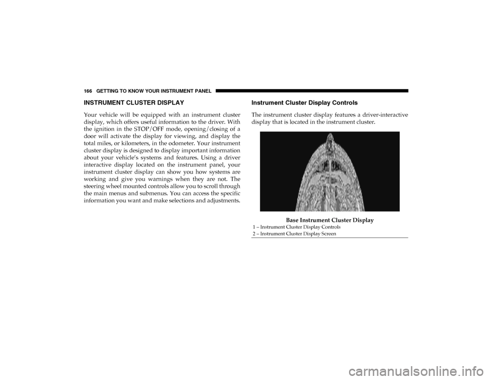
The instrument cluster display features a driver-interactive
display that is located in the instrument cluster.Base Instrument Cluster Display
1 – Instrument Cluster Display Controls
2 – Instrument Cluster Display Screen
2020_DT_1500_OM_US.book Page 166
Page 169 of 674
GETTING TO KNOW YOUR INSTRUMENT PANEL 167
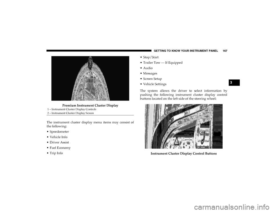
Premium Instrument Cluster Display
The instrument cluster display menu items may consist of
the following:
• Speedometer
• Vehicle Info
• Driver Assist
• Fuel Economy
• Trip Info • Stop/Start
• Trailer Tow — If Equipped
• Audio
• Messages
• Screen Setup
• Vehicle Settings
The system allows the driver to select information by
pushing the following instrument cluster display control
buttons located on the left side of the steering wheel:
Instrument Cluster Display Control Buttons
1 – Instrument Cluster Display Controls
2 – Instrument Cluster Display Screen
3
2020_DT_1500_OM_US.book Page 167
Page 172 of 674
170 GETTING TO KNOW YOUR INSTRUMENT PANEL
Driver Assist — If Equipped
The Driver Assist menu displays the status of the ACC and
LaneSense systems.
Push and release the up or down arrow button until the
Driver Assist menu is displayed in the instrument cluster
display.
Adaptive Cruise Control (ACC) Feature
The instrument cluster display displays the current Adap -
tive Cruise Control (ACC) system settings. The information
displayed depends on ACC system status.
Push the Adaptive Cruise Control (ACC) on/off button
(located on the steering wheel) until one of the following
displays in the instrument cluster display:
Adaptive Cruise Control Off
When ACC is deactivated, the display will read “Adaptive
Cruise Control Off.”
Adaptive Cruise Control Ready
When ACC is activated but the vehicle speed setting has not
been selected, the display will read “Adaptive Cruise
Control Ready.” Push the SET + or the SET- button (located on the steering
wheel) and the following will display in the instrument
cluster display:
ACC SET
When ACC is set, the set speed will display in the instrument
cluster.
The ACC screen may display once again if any ACC activity
occurs, which may include any of the following:
• Distance Setting Change
• System Cancel
• Driver Override
• System Off
• ACC Proximity Warning
• ACC Unavailable Warning
For further information, refer to “Adaptive Cruise Control
(ACC) — If Equipped” in “Starting And Operating.”
2020_DT_1500_OM_US.book Page 170
Page 184 of 674
182 GETTING TO KNOW YOUR INSTRUMENT PANEL
NOTE:
This light may turn on if the accelerator and brake pedals are
pressed at the same time.
If the light continues to flash when the vehicle is running,
immediate service is required and you may experience
reduced performance, an elevated/rough idle, or engine
stall and your vehicle may require towing. The light will
come on when the ignition is placed in the ON/RUN or
ACC/ON/RUN position and remain on briefly as a bulb
check. If the light does not come on during starting, have the
system checked by an authorized dealer. — Electric Power Steering Fault Warning Light
This warning light will turn on when there's a fault with the
Electric Power Steering (EPS) system. Refer to “Power Steering”
in “Starting And Operating” for further information.
— Tailgate Open Warning Light
This warning light will illuminate when the tailgate is open.
NOTE:
If the vehicle is moving, there will also be a single chime.
— Trailer Brake Disconnected Warning Light
This warning light will illuminate when the Trailer Brake has
been disconnected.
— Transmission Temperature Warning Light — If
Equipped
This warning light will illuminate to warn of a high transmis -
sion fluid temperature. This may occur with strenuous usage
such as trailer towing. If this light turns on, stop the vehicle
and run the engine at idle or slightly faster, with the trans -
mission in PARK or NEUTRAL, until the light turns off.
Once the light turns off, you may continue to drive normally.
WARNING!
Continued operation with reduced assist could pose a
safety risk to yourself and others. Service should be
obtained as soon as possible.
WARNING!
If you continue operating the vehicle when the
Transmission Temperature Warning Light is illuminated
you could cause the fluid to boil over, come in contact
with hot engine or exhaust components and cause a fire.
2020_DT_1500_OM_US.book Page 182
Page 187 of 674
GETTING TO KNOW YOUR INSTRUMENT PANEL 185
— Electronic Stability Control (ESC) Off Warning
Light — If Equipped
This warning light indicates the Electronic Stability Control
(ESC) is off.
Each time the ignition is turned to ON/RUN or ACC/ON/
RUN, the ESC system will be on, even if it was turned off
previously.
— LaneSense Warning Light — If Equipped
The LaneSense system provides the driver with visual and
steering torque warnings when the vehicle starts to drift out
of its lane unintentionally without the use of a turn signal.
• When the LaneSense system senses a lane drift situation, the LaneSense indicator changes from solid green to solid
yellow.
• When the LaneSense system senses the lane has been approached and is in a lane departure situation, the Lane -
Sense indicator changes from solid white/green to
flashing yellow.
• Refer to “LaneSense – If Equipped” in “Starting And Oper -
ating” for further information. — Service LaneSense Warning Light — If Equipped
This warning light will illuminate when the LaneSense
system is not operating and requires service. Please see an
authorized dealer.
— Low Washer Fluid Warning Light — If Equipped
This warning light will illuminate when the windshield
washer fluid is low.
— Low Fuel Warning Light
When the fuel level reaches approximately 1.5 gal (5.5 L) this
light will turn on, and remain on until fuel is added.
A single warning chime will sound with Low Fuel Warning.
— Tire Pressure Monitoring System (TPMS) Warning
Light
The warning light switches on and a message is displayed to
indicate that the tire pressure is lower than the recom -
mended value and/or that slow pressure loss is occurring. In
these cases, optimal tire duration and fuel consumption may
not be guaranteed.
3
2020_DT_1500_OM_US.book Page 185
Page 188 of 674
186 GETTING TO KNOW YOUR INSTRUMENT PANEL
Should one or more tires be in the condition mentioned
above, the display will show the indications corresponding
to each tire.
Each tire, including the spare (if provided), should be
checked monthly when cold and inflated to the inflation
pressure recommended by the vehicle manufacturer on the
vehicle placard or tire inflation pressure label. (If your
vehicle has tires of a different size than the size indicated on
the vehicle placard or tire inflation pressure label, you
should determine the proper tire inflation pressure for those
tires.)
As an added safety feature, your vehicle has been equipped
with a Tire Pressure Monitoring System (TPMS) that illumi-
nates a low tire pressure telltale when one or more of your
tires is significantly under-inflated. Accordingly, when the
low tire pressure telltale illuminates, you should stop and check your tires as soon as possible, and inflate them to the
proper pressure. Driving on a significantly under-inflated
tire causes the tire to overheat and can lead to tire failure.
Under-inflation also reduces fuel efficiency and tire tread
life, and may affect the vehicle’s handling and stopping
ability.
Please note that the TPMS is not a substitute for proper tire
maintenance, and it is the driver’s responsibility to maintain
correct tire pressure, even if under-inflation has not reached
the level to trigger illumination of the TPMS low tire pres
-
sure telltale.
Your vehicle has also been equipped with a TPMS malfunc -
tion indicator to indicate when the system is not operating
properly. The TPMS malfunction indicator is combined with
the low tire pressure telltale. When the system detects a
malfunction, the telltale will flash for approximately one
minute and then remain continuously illuminated. This
sequence will continue upon subsequent vehicle start-ups as
long as the malfunction exists. When the malfunction indi -
cator is illuminated, the system may not be able to detect or
signal low tire pressure as intended. TPMS malfunctions
may occur for a variety of reasons, including the installation
of replacement or alternate tires or wheels on the vehicle that
prevent the TPMS from functioning properly. Always check
the TPMS malfunction telltale after replacing one or more
CAUTION!
Do not continue driving with one or more flat tires as
handling may be compromised. Stop the vehicle,
avoiding sharp braking and steering. If a tire puncture
occurs, repair immediately using the dedicated tire
repair kit and contact an authorized dealer as soon as
possible.
2020_DT_1500_OM_US.book Page 186
Page 201 of 674
SAFETY 199
ABS is designed to function with the Original Equipment
Manufacturer (OEM) tires. Modification may result in
degraded ABS performance.
Anti-Lock Brake Warning Light
The yellow “Anti-Lock Brake Warning Light” will turn on
when the ignition is turned to the ON/RUN mode and may
stay on for as long as four seconds.If the “Anti-Lock Brake Warning Light” remains on or comes
on while driving, it indicates that the anti-lock portion of the
brake system is not functioning and that service is required.
However, the conventional brake system will continue to
operate normally if the “Anti-Lock Brake Warning Light” is
on.
If the “Anti-Lock Brake Warning Light” is on, the brake
system should be serviced as soon as possible to restore the
benefits of anti-lock brakes. If the “Anti-Lock Brake Warning
Light” does not come on when the ignition is turned to the
ON/RUN mode, have the light repaired as soon as possible.
Electronic Brake Control System
Your vehicle is equipped with an advanced Electronic Brake
Control (EBC) system. This system includes Electronic Brake
Force Distribution (EBD), Anti-Lock Brake System (ABS),
Brake Assist System (BAS), Hill Start Assist (HSA), Traction
Control System (TCS), Electronic Stability Control (ESC),
and Electronic Roll Mitigation (ERM). These systems work
together to enhance both vehicle stability and control in
various driving conditions.
Your vehicle may also be equipped with Trailer Sway
Control (TSC) and Hill Descent Control (HDC).
• The ABS cannot prevent the natural laws of physics
from acting on the vehicle, nor can it increase braking
or steering efficiency beyond that afforded by the
condition of the vehicle brakes and tires or the traction
afforded.
• The ABS cannot prevent collisions, including those resulting from excessive speed in turns, following
another vehicle too closely, or hydroplaning.
• The capabilities of an ABS equipped vehicle must never be exploited in a reckless or dangerous manner
that could jeopardize the user’s safety or the safety of
others.
WARNING! (Continued)
4
2020_DT_1500_OM_US.book Page 199
Page 202 of 674
200 SAFETY
Brake Assist System (BAS)
The Brake Assist System (BAS) is designed to optimize the
vehicle’s braking capability during emergency braking
maneuvers. The system detects an emergency braking situa-
tion by sensing the rate and amount of brake application, and
then applies optimum pressure to the brakes. This can help
reduce braking distances. The BAS complements the
Anti-lock Brake System (ABS). Applying the brakes very
quickly results in the best BAS assistance. To receive the
benefit of the system, you must apply continuous braking
pressure during the stopping sequence, (do not “pump” the
brakes). Do not reduce brake pedal pressure unless braking
is no longer desired. Once the brake pedal is released, the
BAS is deactivated. Brake System Warning Light
The red “Brake System Warning Light” will turn on when
the ignition is turned to the ON/RUN mode and may stay on
for as long as four seconds.
If the “Brake System Warning Light” remains on or comes on
while driving, it indicates that the brake system is not func
-
tioning properly and that immediate service is required. If
the “Brake System Warning Light” does not come on when
the ignition is turned to the ON/RUN mode, have the light
repaired as soon as possible.
Electronic Brake Force Distribution (EBD)
This function manages the distribution of the braking torque
between the front and rear axles by limiting braking pressure
to the rear axle. This is done to prevent overslip of the rear
wheels to avoid vehicle instability, and to prevent the rear
axle from entering ABS before the front axle.
Electronic Roll Mitigation (ERM)
The Electronic Roll Mitigation (ERM) system anticipates the
potential for wheel lift by monitoring the driver’s steering
wheel input and the speed of the vehicle. When ERM deter -
mines that the rate of change of the steering wheel angle and
vehicle’s speed are sufficient to potentially cause wheel lift,
WARNING!
The Brake Assist System (BAS) cannot prevent the
natural laws of physics from acting on the vehicle, nor
can it increase the traction afforded by prevailing road
conditions. BAS cannot prevent collisions, including
those resulting from excessive speed in turns, driving on
very slippery surfaces, or hydroplaning. The capabilities
of a BAS-equipped vehicle must never be exploited in a
reckless or dangerous manner, which could jeopardize
the user's safety or the safety of others.
2020_DT_1500_OM_US.book Page 200