turn signal Ram 1500 2020 Owner's Guide
[x] Cancel search | Manufacturer: RAM, Model Year: 2020, Model line: 1500, Model: Ram 1500 2020Pages: 674, PDF Size: 32.69 MB
Page 393 of 674

STARTING AND OPERATING 391
LANESENSE — IF EQUIPPED
LaneSense Operation
The LaneSense system is operational at speeds above 37 mph
(60 km/h) and below 112 mph (180 km/h). It uses a forward
looking camera to detect lane markings and measure vehicle
position within the lane boundaries.
When both lane markings are detected and the driver unin -
tentionally drifts out of the lane while no turn signal has been
applied OR the driver departs the lane on the opposite side
of the applied turn signal (if the left turn signal is applied and
the vehicle departs to the right), the LaneSense system
provides a haptic warning in the form of torque applied to
the steering wheel to prompt the driver to remain within the
lane boundaries. The LaneSense system will also provide a
visual warning through the instrument cluster display to
prompt the driver to remain within the lane boundaries.
The driver may manually override the haptic warning by
applying torque into the steering wheel at any time. When only a single lane marking is detected and the driver
unintentionally drifts across that lane marking (no turn
signal applied), the LaneSense system provides a visual
warning through the instrument cluster display to prompt
the driver to remain within the lane. When only a single lane
marking is detected, a haptic (torque) warning will not be
provided.
NOTE:
When operating conditions have been met, the LaneSense
system will monitor if the driver’s hands are on the steering
wheel and provides an audible and visual warning to the
driver when the driver’s hands are not detected on the
steering wheel. The system will cancel if the driver does not
return their hands to the wheel.
Turning LaneSense On Or Off
The LaneSense button is located on the switch panel
below the Uconnect display.
NOTE:
If your vehicle is equipped with a 12–inch Uconnect Display
screen, the LaneSense button is located above the display.
5
2020_DT_1500_OM_US.book Page 391
Page 397 of 674
STARTING AND OPERATING 395
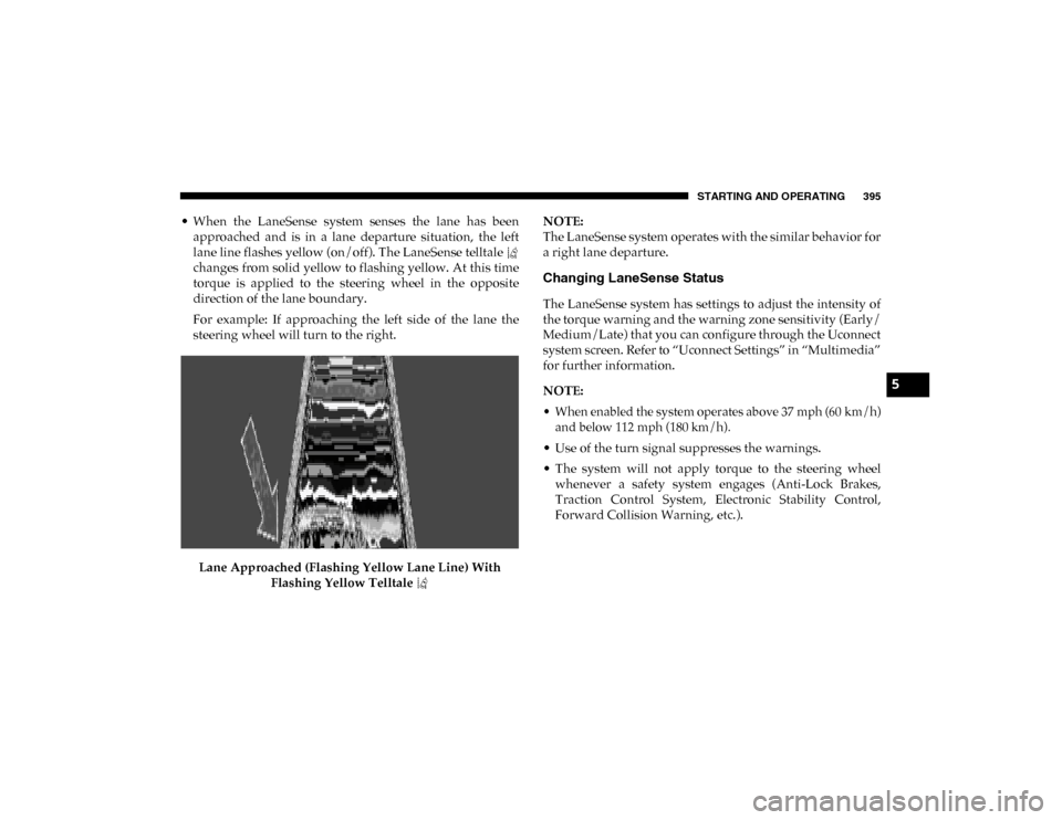
• When the LaneSense system senses the lane has beenapproached and is in a lane departure situation, the left
lane line flashes yellow (on/off). The LaneSense telltale
changes from solid yellow to flashing yellow. At this time
torque is applied to the steering wheel in the opposite
direction of the lane boundary.
For example: If approaching the left side of the lane the
steering wheel will turn to the right.
Lane Approached (Flashing Yellow Lane Line) With Flashing Yellow Telltale NOTE:
The LaneSense system operates with the similar behavior for
a right lane departure.
Changing LaneSense Status
The LaneSense system has settings to adjust the intensity of
the torque warning and the warning zone sensitivity (Early/
Medium/Late) that you can configure through the Uconnect
system screen. Refer to “Uconnect Settings” in “Multimedia”
for further information.
NOTE:
• When enabled the system operates above 37 mph (60 km/h)
and below 112 mph (180 km/h).
• Use of the turn signal suppresses the warnings.
• The system will not apply torque to the steering wheel whenever a safety system engages (Anti-Lock Brakes,
Traction Control System, Electronic Stability Control,
Forward Collision Warning, etc.).
5
2020_DT_1500_OM_US.book Page 395
Page 421 of 674
STARTING AND OPERATING 419
Towing Requirements — Trailer Lights And Wiring
Whenever you pull a trailer, regardless of the trailer size,
stoplights and turn signals on the trailer are required for
motoring safety.
The Trailer Tow Package may include a four- and seven-pin
wiring harness. Use a factory approved trailer harness and
connector.
NOTE:
Do not cut or splice wiring into the vehicle’s wiring harness.
The electrical connections are all complete to the vehicle but
you must mate the harness to a trailer connector. Refer to the
following illustrations.
NOTE:
• Disconnect trailer wiring connector from the vehiclebefore launching a boat (or any other device plugged into
vehicle’s electrical connect) into water.
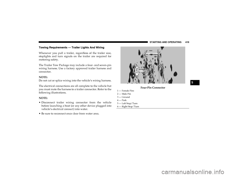
• Be sure to reconnect once clear from water area. Four-Pin Connector
1 — Female Pins
2 — Male Pin
3 — Ground
4 — Park
5 — Left Stop/Turn
6 — Right Stop/Turn
5
2020_DT_1500_OM_US.book Page 419
Page 433 of 674
431
IN CASE OF EMERGENCY
HAZARD WARNING FLASHERS
The Hazard Warning switch is located on the upper
switch bank just below the radio.
NOTE:
If your vehicle is equipped with a 12–inch Uconnect display,
the Hazard Warning switch is located above the display.
Push the switch to turn on the Hazard Warning flasher.
When the switch is activated, all directional turn signals will
flash on and off to warn oncoming traffic of an emergency.
Push the switch a second time to turn off the Hazard
Warning flashers.
This is an emergency warning system and it should not be
used when the vehicle is in motion. Use it when your vehicle
is disabled and it is creating a safety hazard for other motor -
ists.
When leaving the vehicle to seek assistance, the Hazard
Warning flashers will continue to operate even though the
ignition is placed in the OFF position. NOTE:
With extended use the Hazard Warning flashers may wear
down your battery.
ASSIST AND SOS SYSTEM — IF EQUIPPED
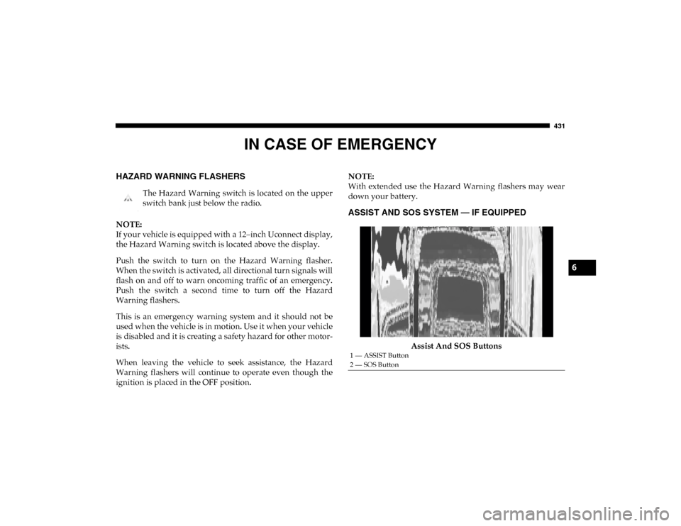
Assist And SOS Buttons
1 — ASSIST Button
2 — SOS Button
6
2020_DT_1500_OM_US.book Page 431
Page 437 of 674
IN CASE OF EMERGENCY 435
Even if the SOS Call system is fully functional, factors
beyond FCA US LLC’s control may prevent or stop the SOS
Call system operation. These include, but are not limited to,
the following factors:
• Delayed accessories mode is active
• The ignition is in the OFF position
• The vehicle’s electrical systems are not intact
• The SOS Call system software and/or hardware aredamaged during a crash
• The vehicle battery loses power or becomes disconnected during a vehicle crash
• LTE (voice/data) or 4G (data) network and/or Global Positioning Satellite signals are unavailable or obstructed
• Equipment malfunction at the SOS operator facility • Operator error by the SOS operator
• LTE (voice/data) or 4G (data) network congestion
• Weather
• Buildings, structures, geographic terrain, or tunnels
NOTE:
• Your vehicle may be transmitting data as authorized by
the subscriber.
• Never place anything on or near the vehicle’s LTE (voice/ data) or 4G (data) and GPS antennas. You could prevent
LTE (voice/data) or 4G (data) and GPS signal reception,
which can prevent your vehicle from placing an emer -
gency call. An operable LTE (voice/data) or 4G (data)
network connection and a GPS signal is required for the
SOS Call system to function properly.
• The Occupant Restraint Control module turns on the
air bag Warning Light on the instrument panel if a
malfunction in any part of the system is detected. If the
Air Bag Warning Light is illuminated, have your autho -
rized dealer service the Occupant Restraint Control
system immediately.
WARNING! (Continued)
WARNING!
ALWAYS obey traffic laws and pay attention to the road.
ALWAYS drive safely with your hands on the steering
wheel. You have full responsibility and assume all risks
related to the use of the features and applications in this
vehicle. Only use the features and applications when it is
safe to do so. Failure to do so may result in an accident
involving serious injury or death.
6
2020_DT_1500_OM_US.book Page 435
Page 439 of 674
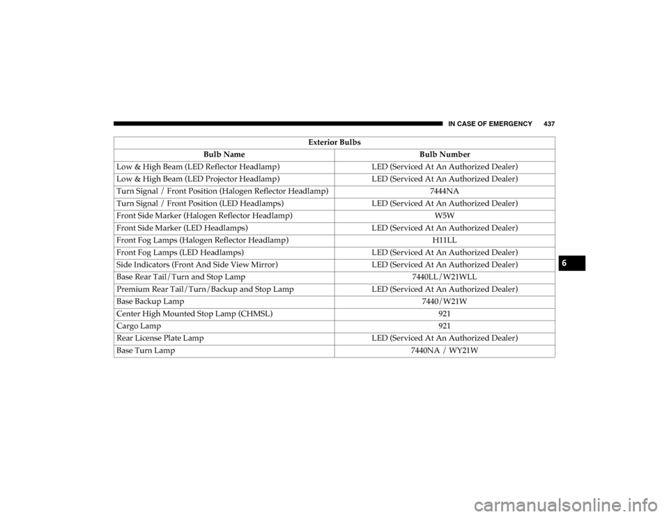
IN CASE OF EMERGENCY 437
Low & High Beam (LED Reflector Headlamp)LED (Serviced At An Authorized Dealer)
Low & High Beam (LED Projector Headlamp) LED (Serviced At An Authorized Dealer)
Turn Signal / Front Position (Halogen Reflector Headlamp) 7444NA
Turn Signal / Front Position (LED Headlamps) LED (Serviced At An Authorized Dealer)
Front Side Marker (Halogen Reflector Headlamp) W5W
Front Side Marker (LED Headlamps) LED (Serviced At An Authorized Dealer)
Front Fog Lamps (Halogen Reflector Headlamp) H11LL
Front Fog Lamps (LED Headlamps) LED (Serviced At An Authorized Dealer)
Side Indicators (Front And Side View Mirror) LED (Serviced At An Authorized Dealer)
Base Rear Tail/Turn and Stop Lamp 7440LL/W21WLL
Premium Rear Tail/Turn/Backup and Stop Lamp LED (Serviced At An Authorized Dealer)
Base Backup Lamp 7440/W21W
Center High Mounted Stop Lamp (CHMSL) 921
Cargo Lamp 921
Rear License Plate Lamp LED (Serviced At An Authorized Dealer)
Base Turn Lamp 7440NA / WY21W
Exterior Bulbs
Bulb Name Bulb Number
6
2020_DT_1500_OM_US.book Page 437
Page 443 of 674
IN CASE OF EMERGENCY 441
NOTE:
It may be necessary to remove/reposition Air Cleaner
Assembly to access passenger side headlamp/side marker
light bulbs.
4. Disengage the side marker socket by rotating counter-clockwise a quarter turn.
5. Pull the socket and bulb straight out from the housing.
6. Separate the bulb from the socket without twisting.
7. Reverse the procedure for installation of new bulb and covers.
Fog Lamps — If Equipped
1. Reach under and behind the front bumper to access the back of the front fog lamp housing.
2. Disconnect the fog lamp wiring harness connector from the fog lamp bulb.
3. Rotate the bulb counterclockwise a quarter turn to unlock the bulb from the housing.
4. Pull the bulb straight out from the housing. Rear Tail/Stop, Turn Signal And Backup Lamps
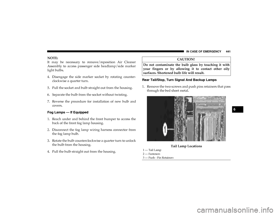
1. Remove the two screws and push pins retainers that pass
through the bed sheet metal.
Tail Lamp LocationsCAUTION!
Do not contaminate the bulb glass by touching it with
your fingers or by allowing it to contact other oily
surfaces. Shortened bulb life will result.
1 — Tail Lamp
2 — Fasteners
3 — Push - Pin Retainers
6
2020_DT_1500_OM_US.book Page 441
Page 589 of 674

MULTIMEDIA 587
Auto Unlock On ExitOn Off
NOTE:
When the “Auto Unlock On Exit” feature is selected, all doors unlock when the vehicle is stopped and the transmission is in
the PARK or NEUTRAL position and the driver's door is opened. Flash Lights With Lock On Off
NOTE:
When the “Flash Lights With Lock” feature is selected, the front and rear turn signals flash when the doors are locked or
unlocked with the key fob. This feature may be selected with or without the “Sound Horn With Lock” feature selected. Sound Horn With Lock Off1st Press 2nd Press
Sound Horn With Remote Start On
Off
Setting Name
Selectable Options
9
2020_DT_1500_OM_US.book Page 587
Page 593 of 674

MULTIMEDIA 591
Air Suspension — If Equipped
After pressing the Suspension button on the touchscreen, the following settings will be available:Headlight Off Delay
–+
NOTE:
When the “Headlight Off Delay” feature is selected, the driver can choose to have the headlights remain on for 0, 30, 60, or
90 seconds when exiting the vehicle. Auto Entry/Exit — If Equipped OnOff
Easy Exit Seat — If Equipped OnOff
NOTE:
When the “Easy Exit Seat” feature is selected, the Driver’s seat will automatically move rearward once the engine is shut off. Setting Name
Selectable Options
Setting NameSelectable Options
Sound Horn With Lower On Off
NOTE:
When the “Sound Horn With Lower” feature is selected, a short horn sound will occur when the key fob remote lower button
is pushed. Flash Lights With Lower On Off
NOTE:
When the “Flash Lights With Lower” feature is selected, the front and rear turn signals will flash when the key fob remote
lower button is pressed twice. This feature may be selected with or without the Sound Horn on Lower feature selected.
9
2020_DT_1500_OM_US.book Page 591
Page 612 of 674

610 MULTIMEDIA
Doors & Locks
After pressing the Doors & Locks button on the touchscreen, the following settings will be available:Setting Name Selectable Options
Auto Door Locks On Off
Auto Unlock On Exit OnOff
NOTE:
When the “Auto Unlock On Exit” feature is selected, all doors unlock when the vehicle is stopped and the transmission is in
the PARK or NEUTRAL position and the driver's door is opened. Flash Lights With Lock OnOff
NOTE:
When the “Flash Lights With Lock” feature is selected, the front and rear turn signals flash when the doors are locked or
unlocked with the key fob. This feature may be selected with or without the “Sound Horn With Lock” feature selected.
Sound Horn With Lock — If Equipped Off1st Press 2nd Press
Sound Horn With Remote Start OnOff
2020_DT_1500_OM_US.book Page 610