key Ram 1500 2020 Service Manual
[x] Cancel search | Manufacturer: RAM, Model Year: 2020, Model line: 1500, Model: Ram 1500 2020Pages: 674, PDF Size: 32.69 MB
Page 141 of 674
GETTING TO KNOW YOUR VEHICLE 139
Locking And Unlocking RamBox
Push and release the lock or unlock button on the key fob to
lock and unlock all doors, the tailgate and the RamBox (if
equipped). Refer to “Keys” in this chapter for further details.
To unlatch the storage bin manually, insert the emergency
key into the keyhole and turn clockwise. Always return the
key to the upright (vertical) position before removing it from
the keyhole.RamBox Safety Warning
Carefully follow these warnings to help prevent personal
injury or damage to your vehicle:
CAUTION!
• Ensure cargo bin lids are closed and latched before moving or driving vehicle.
• Loads applied to the top of the bin lid should be mini -
mized to prevent damage to the lid and latching/
hinging mechanisms.
• Damage to the RamBox bin may occur due to heavy/ sharp objects placed in bin that shift due to vehicle
motion. In order to minimize potential for damage,
secure all cargo to prevent movement and protect inside
surfaces of bin from heavy/sharp objects with appro -
priate padding.
WARNING!
• Always close the storage bin covers when your vehicle is unattended.
• Do not allow children to have access to the storage bins. Once in the storage bin, young children may not be able
to escape. If trapped in the storage bin, children can die
from suffocation or heat stroke.
• In an accident, serious injury could result if the storage bin covers are not properly latched.
• Do not drive the vehicle with the storage bin covers open.
• Keep the storage bin covers closed and latched while the vehicle is in motion.
• Do not use a storage bin latch as a tie down.2
2020_DT_1500_OM_US.book Page 139
Page 143 of 674

GETTING TO KNOW YOUR VEHICLE 141
To install the bed divider into the storage position, perform
the following:
1. Make sure the center handle is unlocked using the vehiclekey and rotate the center handle vertically to release the
divider side gates.
Center Handle And Lock 2. With the side gates open, position the divider fully
forward in the bed against the front panel.
Storage Position
1 — Center Handle Lock
2 — Handle
2
2020_DT_1500_OM_US.book Page 141
Page 144 of 674

142 GETTING TO KNOW YOUR VEHICLE
3. Rotate the side gates closed allowing the outboard ends tobe positioned in front of the cargo tie down loops.
Cargo Tie Down Loop 4. Rotate the center handle horizontally to secure the side
gates in the closed position.
Side Gates Closed
5. Lock the center handle using the vehicle key to secure the panel into place.
2020_DT_1500_OM_US.book Page 142
Page 145 of 674

GETTING TO KNOW YOUR VEHICLE 143
Divider Position
The divider position is intended for managing your cargo
and assisting in keeping cargo from moving around the bed.
There are 11 divider slots along the bed inner panels which
allow for various positions to assist in managing your cargo.
To install the bed divider into a divider position, perform the
following:
1. Make sure the center handle is unlocked using the vehiclekey and rotate the center handle vertically to release the
divider side gates.
Center Handle And Lock
1 — Center Handle Lock
2 — Handle
2
2020_DT_1500_OM_US.book Page 143
Page 149 of 674
GETTING TO KNOW YOUR VEHICLE 147
NOTE:
When a cap or pickup camper is installed on a vehicle, an
alternate Center High-Mounted Stop Light (CHMSL) must
be provided.
EASY-OFF TAILGATE
To simplify mounting of a camper unit with an overhang, the
tailgate can be removed.
NOTE:
The electric connector at the bottom of the tailgate must be
disconnected prior to removing the tailgate.
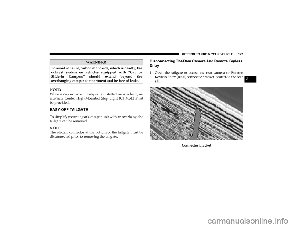
Disconnecting The Rear Camera And Remote Keyless
Entry
1. Open the tailgate to access the rear camera or RemoteKeyless Entry (RKE) connector bracket located on the rear
sill.
Connector Bracket
WARNING!
To avoid inhaling carbon monoxide, which is deadly, the
exhaust system on vehicles equipped with “Cap or
Slide-In Campers” should extend beyond the
overhanging camper compartment and be free of leaks.
2
2020_DT_1500_OM_US.book Page 147
Page 150 of 674
148 GETTING TO KNOW YOUR VEHICLE
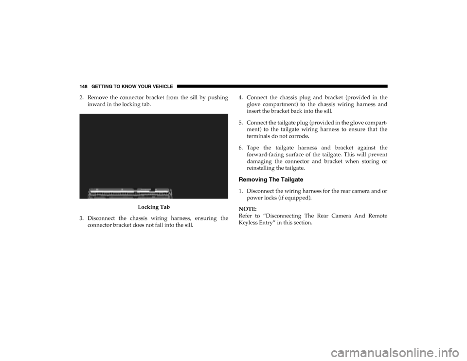
2. Remove the connector bracket from the sill by pushinginward in the locking tab.
Locking Tab
3. Disconnect the chassis wiring harness, ensuring the connector bracket does not fall into the sill. 4. Connect the chassis plug and bracket (provided in the
glove compartment) to the chassis wiring harness and
insert the bracket back into the sill.
5. Connect the tailgate plug (provided in the glove compart -
ment) to the tailgate wiring harness to ensure that the
terminals do not corrode.
6. Tape the tailgate harness and bracket against the forward-facing surface of the tailgate. This will prevent
damaging the connector and bracket when storing or
reinstalling the tailgate.
Removing The Tailgate
1. Disconnect the wiring harness for the rear camera and orpower locks (if equipped).
NOTE:
Refer to “Disconnecting The Rear Camera And Remote
Keyless Entry” in this section.
2020_DT_1500_OM_US.book Page 148
Page 152 of 674

150 GETTING TO KNOW YOUR VEHICLE
Locking Tailgate
The tailgate can be locked using the key fob lock button.
TRI-FOLD TONNEAU COVER — IF EQUIPPED
Your vehicle may be equipped with a Tri-Fold Tonneau
Cover which consists of different features:
• Easy Tri-Fold cover
• Tonneau fore aft locator
• Crossbar inside bed locator
• Front and rear clamps
• Stowage strap
• Locking capability
Tri-Fold Tonneau Cover Removal
To remove the Tonneau Cover follow the following steps:
1. Open the tailgate to access the rear pair of Tonneau Coverclamps located on the underside of the Cover (left and
right side).
Clamped Position
2020_DT_1500_OM_US.book Page 150
Page 225 of 674
SAFETY 223
FCW Message
When the system determines a collision with the vehicle in
front of you is no longer probable, the warning message will
be deactivated.
NOTE:
• The minimum speed for FCW activation is 3 mph (5 km/h).
• The FCW alerts may be triggered on objects other than vehicles such as guard rails or sign posts based on the
course prediction. This is expected and is a part of normal
FCW activation and functionality. • It is unsafe to test the FCW system. To prevent such misuse
of the system, after four Active Braking events within a
key cycle, the Active Braking portion of FCW will be deac -
tivated until the next key cycle.
• The FCW system is intended for on-road use only. If the vehicle is taken off-road, the FCW system should be deac -
tivated to prevent unnecessary warnings to the surround -
ings.
WARNING!
Forward Collision Warning (FCW) is not intended to
avoid a collision on its own, nor can FCW detect every
type of potential collision. The driver has the
responsibility to avoid a collision by controlling the
vehicle via braking and steering. Failure to follow this
warning could lead to serious injury or death.4
2020_DT_1500_OM_US.book Page 223
Page 265 of 674
SAFETY 263
(Continued)
Your vehicle may also be designed to perform any of these
other functions in response to the Enhanced Accident
Response System:
• Turn off the Fuel Filter Heater, Turn off the HVAC BlowerMotor, Close the HVAC Circulation Door
• Cut off battery power to the: • Engine
• Electric Motor (if equipped)
• Electric power steering
• Brake booster
• Electric park brake
• Automatic transmission gear selector
• Horn
• Front wiper
• Headlamp washer pump
NOTE:
After an accident, remember to cycle the ignition to the STOP
(OFF/LOCK) position and remove the key from the ignition
switch to avoid draining the battery. Carefully check the
vehicle for fuel leaks in the engine compartment and on the
ground near the engine compartment and fuel tank before
resetting the system and starting the engine. If there are no
fuel leaks or damage to the vehicle electrical devices (e.g. headlights) after an accident, reset the system by following
the procedure described below. If you have any doubt,
contact an authorized dealer.
Enhanced Accident Response System Reset Procedure
In order to reset the Enhanced Accident Response System
functions after an event, the ignition switch must be changed
from ignition START or ON/RUN to ignition OFF. Carefully
check the vehicle for fuel leaks in the engine compartment
and on the ground near the engine compartment and fuel
tank before resetting the system and starting the engine.
Maintaining Your Air Bag System
WARNING!
• Modifications to any part of the air bag system could cause it to fail when you need it. You could be injured
if the air bag system is not there to protect you. Do not
modify the components or wiring, including adding
any kind of badges or stickers to the steering wheel hub
trim cover or the upper passenger side of the instru -
ment panel. Do not modify the front bumper, vehicle
body structure, or add aftermarket side steps or
running boards.
4
2020_DT_1500_OM_US.book Page 263
Page 290 of 674
288 SAFETY
(Continued)
• ONLY install floor mats designed to fit your vehicle.NEVER install a floor mat that cannot be properly
attached and secured to your vehicle. If a floor mat
needs to be replaced, only use a FCA approved floor
mat for the specific make, model, and year of your
vehicle.
• ONLY use the driver’s side floor mat on the driver’s side floor area. To check for interference, with the
vehicle properly parked with the engine off, fully
depress the accelerator, the brake, and the clutch pedal
(if present) to check for interference. If your floor mat
interferes with the operation of any pedal, or is not
secure to the floor, remove the floor mat from the
vehicle and place the floor mat in your trunk.
• ONLY use the passenger’s side floor mat on the passenger’s side floor area.
• ALWAYS make sure objects cannot fall or slide into the driver’s side floor area when the vehicle is moving.
Objects can become trapped under accelerator, brake,
or clutch pedals and could cause a loss of vehicle
control.
WARNING! (Continued)
• NEVER place any objects under the floor mat (e.g.,
towels, keys, etc.). These objects could change the posi -
tion of the floor mat and may cause interference with
the accelerator, brake, or clutch pedals.
• If the vehicle carpet has been removed and re-installed, always properly attach carpet to the floor and check the
floor mat fasteners are secure to the vehicle carpet.
Fully depress each pedal to check for interference with
the accelerator, brake, or clutch pedals then re-install
the floor mats.
• It is recommended to only use mild soap and water to clean your floor mats. After cleaning, always check
your floor mat has been properly installed and is
secured to your vehicle using the floor mat fasteners by
lightly pulling mat.
WARNING! (Continued)
2020_DT_1500_OM_US.book Page 288