key Ram 1500 2020 Repair Manual
[x] Cancel search | Manufacturer: RAM, Model Year: 2020, Model line: 1500, Model: Ram 1500 2020Pages: 674, PDF Size: 32.69 MB
Page 326 of 674

324 STARTING AND OPERATING
The indicator lamps 1 through 5 will illuminate to show the
current position of the vehicle. Flashing indicator lamps will
show a position which the system is working to achieve.
When raising, if multiple indicator lamps are flashing, the
highest flashing indicator lamp is the position the system is
working to achieve. When lowering, if multiple indicators
are flashing, the lowest solid indicator lamp is the position
the system is working to achieve.
Pushing the height selector up once will move the suspen-
sion one position higher from the current position, assuming
all conditions are met (i.e. key in ON/RUN position, engine
running, speed below threshold, etc). The height selector
switch can be pushed up multiple times, each push will raise
the requested level by one position up to a maximum posi -
tion of OR2 or the highest position allowed based on current
conditions (i.e. vehicle speed, etc).
Pushing the height selector down once will move the suspen -
sion one position lower from the current level, assuming all
conditions are met (i.e. key in ON/RUN position, engine
running, doors closed, speed below threshold, etc). The
height selector switch can be pushed down multiple times,
each push will lower the requested level by one position
down to a minimum of Entry/Exit Mode or the lowest posi -
tion allowed based on current conditions (i.e. vehicle speed,
etc.) Automatic height changes will occur based on vehicle speed
and the current vehicle height. The indicator lamps and
instrument cluster display messages will operate the same
for automatic changes and user requested changes.
• Off-Road 2 (OR2) – Indicator lamps 5, 4, 3, 2 and 1 will be
illuminated when the vehicle is in OR2.
• Off-Road 1 (OR1) – Indicator lamps 5, 4, 3 and 2 will be illuminated when the vehicle is in OR1.
• Normal Ride Height (NRH) – Indicator lamps 5, 4 and 3 will be illuminated when the vehicle is in this position.
• Aero Mode – Indicator lamps 5 and 4 will be illuminated when the vehicle is in this position.
• Entry/Exit Mode – Indicator lamp 5 will be illuminated when the vehicle is in Entry Exit Mode. Entry/Exit mode
can be requested up to 33 mph (53 km/h). If vehicle speed
is reduced to, and kept below, 15 mph (24 km/h) indicator
lamp 4 will flash and indicator lamp 5 will remain solid
until Entry/Exit Mode is achieved at which point indicator
lamp 4 will turn off.
• Transport Mode – No indicator lamps will be illuminated. Transport Mode is disabled by driving the vehicle.
2020_DT_1500_OM_US.book Page 324
Page 332 of 674

330 STARTING AND OPERATING
The indicator lamps 1 through 4 will illuminate to show the
current position of the vehicle. Flashing indicator lamps will
show a position which the system is working to achieve.
When raising or lowering, the flashing indicator lamp is the
position the system is working to achieve.
Pushing the height selector switch up once will move the
suspension one position higher from the current position,
assuming all conditions are met (i.e. key in ON/RUN posi-
tion, engine running, speed below threshold, etc). The height
selector switch can be pushed up multiple times, each push
will raise the requested level by one position up to a
maximum position of OR or the highest position allowed
based on current conditions (i.e. vehicle speed, etc).
Pushing the height selector switch down once will move the
suspension one position lower from the current level,
assuming all conditions are met (i.e. key in ON/RUN posi -
tion, engine running, doors closed, speed below threshold,
etc). The height selector switch can be pushed down multiple
times, each push will lower the requested level by one posi -
tion down to a minimum of Entry/Exit Mode or the lowest
position allowed based on current conditions (i.e. vehicle
speed, etc.)
Automatic height changes will occur based on vehicle speed
and the current vehicle height. The indicator lamps and instrument cluster display messages will operate the same
for automatic changes and user requested changes.
• Off-Road 1 (OR1) – Indicator lamps 4, 3, 2, and 1 will be
illuminated when the vehicle is in OR1.
• Normal Ride Height (NRH) – Indicator lamps 4, 3, and 2 will be illuminated when the vehicle is in this position.
• Aero Mode – Indicator lamps 4 and 3 will be illuminated when the vehicle is in this position.
• Entry/Exit Mode – Indicator lamp 4 will be illuminated when the vehicle is in Entry Exit Mode. Entry/Exit mode
can be requested up to 33 mph (53 km/h). If vehicle speed
is reduced to, and kept below, 15 mph (24 km/h) indicator
lamp 3 will flash and indicator lamp 4 will remain solid
until Entry/Exit Mode is achieved at which point indicator
lamp 3 will turn off.
• Transport Mode – No indicator lamps will be illuminated. Transport Mode is disabled by driving the vehicle.
• Tire/Jack Mode – Indicator lamps 4 and 1 will be illumi -
nated. Tire/Jack Mode is disabled by driving the vehicle.
• Wheel Alignment Mode – Indicator lamps 2, 3, and 4 will be illuminated. Wheel Alignment Mode is disabled by
driving the vehicle.
2020_DT_1500_OM_US.book Page 330
Page 338 of 674
336 STARTING AND OPERATING
Conditions That Force An Automatic Shift To Park While
In Autostop Mode
The engine will not start automatically and the transmission
will be placed in PARK if:
• The driver door is open and brake pedal released.
• The driver door is open and the driver seat belt isunbuckled.
• The engine hood has been opened.
• A STOP/START system error present.
The engine may then be restarted by moving the transmis -
sion shift selector out of PARK (e.g. to DRIVE) or, in some
cases, only by a KEY START. The instrument cluster will
display a SHIFT OUT OF PARK message, or a STOP/START
KEY START REQUIRED message, to indicate which action is
required.
Refer to “Instrument Cluster Display” in “Getting To Know
Your Instrument Panel” for further information.To Manually Turn Off The Stop Start System
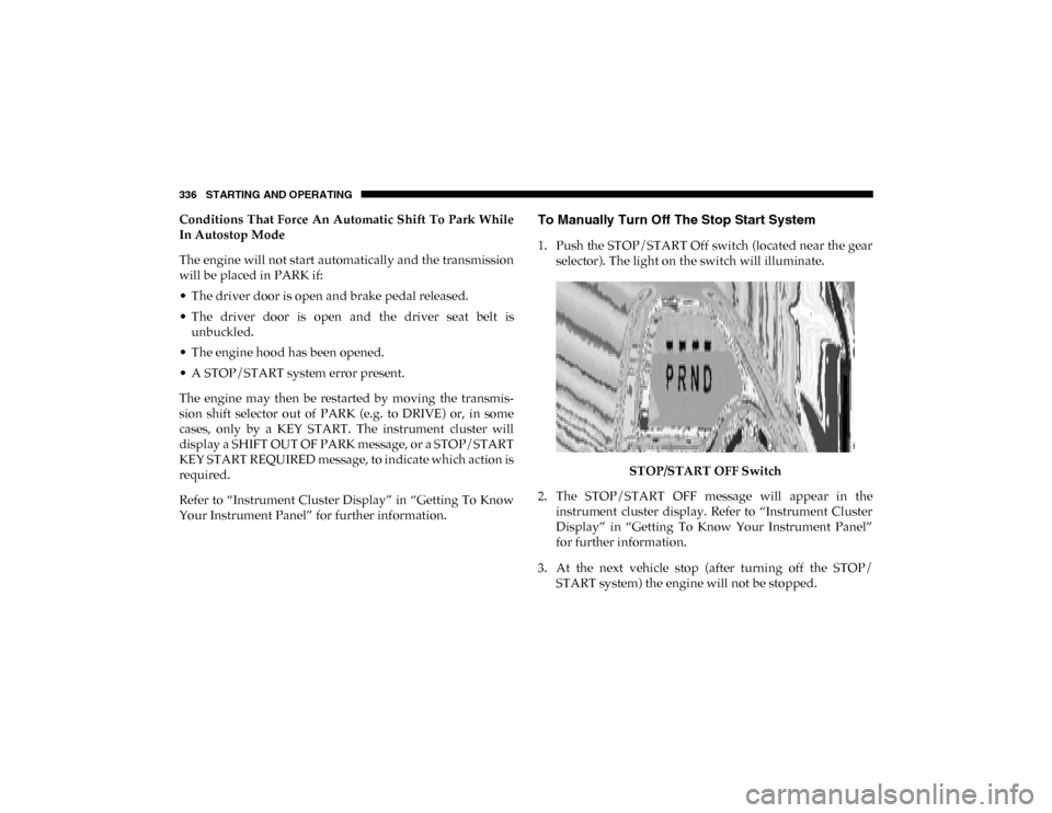
1. Push the STOP/START Off switch (located near the gear selector). The light on the switch will illuminate.
STOP/START OFF Switch
2. The STOP/START OFF message will appear in the instrument cluster display. Refer to “Instrument Cluster
Display” in “Getting To Know Your Instrument Panel”
for further information.
3. At the next vehicle stop (after turning off the STOP/ START system) the engine will not be stopped.
2020_DT_1500_OM_US.book Page 336
Page 339 of 674

STARTING AND OPERATING 337
4. If the STOP/START system is manually turned off, theengine can be started and stopped by cycling the ignition
switch or pressing the STOP/START switch again.
5. The STOP/START system will reset itself back to an ON condition every time the key is turned off and back on.
To Manually Turn On The Stop Start System
1. Push the STOP/START Off switch (located near the gearselector module).
2. The light on the switch will turn off.
System Malfunction
If there is a malfunction in the STOP/START system, the
system will not shut down the engine. A “SERVICE STOP/
START SYSTEM” message will appear in the instrument
cluster display. Refer to “Instrument Cluster Display” in
“Getting To Know Your Instrument Panel” for further infor -
mation.
The system will need to be checked by your authorized
dealer.
SPEED CONTROL — IF EQUIPPED
When engaged, the Speed Control takes over accelerator
operations at speeds greater than 20 mph (32 km/h).
The Speed Control buttons are located on the right side of the
steering wheel.
Speed Control Buttons
1 — CANC/Cancel
2 — SET (+)/Accel
3 — On/Off
4 — RES/Resume
5 — SET (-)/Decel
5
2020_DT_1500_OM_US.book Page 337
Page 371 of 674
STARTING AND OPERATING 369
SENSORS", or the "PARKSENSE UNAVAILABLE SERVICE
REQUIRED" message for five seconds. When the gear
selector is moved to REVERSE and the system has detected a
faulted condition, the instrument cluster display will display
a "WIPE OFF" message on the corresponding blocked system
while the vehicle is in REVERSE. The system will continue to
provide arc alerts for the side that is functioning properly.
Refer to “Instrument Cluster Display” in “Getting To Know
Your Instrument Panel” for further information.
If "PARKSENSE UNAVAILABLE WIPE REAR SENSORS" or
"PARKSENSE UNAVAILABLE WIPE FRONT SENSORS"
appears in the instrument cluster display make sure the
outer surface and the underside of the rear fascia/bumper
and/or front fascia/bumper is clean and clear of snow, ice,
mud, dirt or other obstruction and then cycle the ignition. If
the message continues to appear see your authorized dealer.
NOTE:
Water from a car wash or road slush in freezing weather may
also cause sensors to become blocked.
If the "PARKSENSE UNAVAILABLE SERVICE REQUIRED"
message appears in the instrument cluster display, see your
authorized dealer.Cleaning The ParkSense System
Clean the ParkSense sensors with water, car wash soap and
a soft cloth. Do not use rough or hard cloths. Do not scratch
or poke the sensors. Otherwise, you could damage the
sensors.
ParkSense System Usage Precautions
NOTE:
• Ensure that the front and rear bumper are free of snow, ice,mud, dirt and debris to keep the ParkSense system oper -
ating properly.
• Jackhammers, large trucks, and other vibrations could affect the performance of ParkSense.
• When you turn Front or Rear ParkSense off, the instrument cluster display will show a vehicle graphic of the Front or
Rear ParkSense on/off state for two seconds. Furthermore,
once you turn Front or Rear ParkSense off, it remains off
until you turn it on again, even if you cycle the ignition key.
• When you move the gear selector to the REVERSE position and Front or Rear ParkSense is turned off, the instrument
cluster display will show a vehicle graphic with "OFF" in
the corresponding side. This vehicle graphic will be
displayed for as long as the vehicle is in REVERSE.
5
2020_DT_1500_OM_US.book Page 369
Page 402 of 674
400 STARTING AND OPERATING
Top View
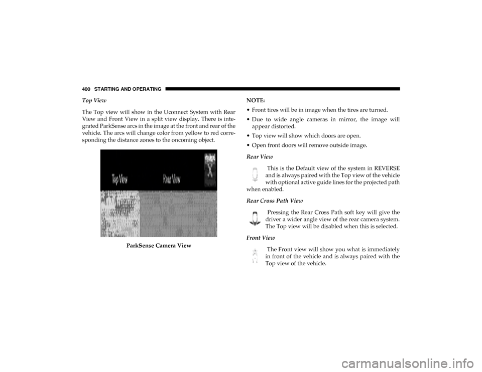
The Top view will show in the Uconnect System with Rear
View and Front View in a split view display. There is inte-
grated ParkSense arcs in the image at the front and rear of the
vehicle. The arcs will change color from yellow to red corre -
sponding the distance zones to the oncoming object.
ParkSense Camera View NOTE:
• Front tires will be in image when the tires are turned.
• Due to wide angle cameras in mirror, the image will
appear distorted.
• Top view will show which doors are open.
• Open front doors will remove outside image.
Rear View
This is the Default view of the system in REVERSE
and is always paired with the Top view of the vehicle
with optional active guide lines for the projected path
when enabled.
Rear Cross Path View
Pressing the Rear Cross Path soft key will give the
driver a wider angle view of the rear camera system.
The Top view will be disabled when this is selected.
Front View The Front view will show you what is immediately
in front of the vehicle and is always paired with the
Top view of the vehicle.
2020_DT_1500_OM_US.book Page 400
Page 403 of 674
STARTING AND OPERATING 401
Front Cross Path View Pressing the Front Cross Path soft key will give the
driver a wider angle view of the front camera system.
The Top view will be disabled when this is selected.
Rear View Camera Pressing the Backup Camera soft key will provide a
full screen rear view with Zoom View.
NOTE:
If the Backup Camera view was selected through the
Surround View Screen, exiting out of the Rear View Camera
screen will return to the Surround View Screen. If the Backup
Camera was manually activated through the Controls menu
of the Uconnect display, exiting out of the display screen will
return to the Controls menu.
Zoom View
When the Rear View Camera image is being displayed, and
the vehicle speed is below 8 mph (13 km/h) while in any
gear selector position, Zoom View is available. By pressing
the “magnifying glass” icon in the upper left of the display
screen, the image will zoom in to four times the standard
view. Pressing the icon a second time will return the view to
the standard Backup Camera display. When Zoom View is selected while the vehicle is in
REVERSE, then shifted to DRIVE, the camera delay view will
display the standard Backup Camera view. If the vehicle is
then returned to REVERSE gear from DRIVE, the Zoom
View selection will automatically resume.
Shifting to NEUTRAL from any gear will maintain the
selected view (Zoom or Standard) as long as the vehicle is
below 8 mph (13 km/h).
If the vehicle is in PARK, Zoom View is available until the
gear selector is placed in DRIVE or REVERSE and speeds are
at or above 8 mph (13 km/h).
NOTE:
• If the vehicle in is DRIVE, NEUTRAL, or REVERSE, and speed is greater than or equal to 8 mph (13 km/h), ZoomView is unavailable and the icon will appear grey.
• While in Zoom View, the guidelines will not be visible.
Deactivation
The system is deactivated in the following conditions if it
was activated automatically:
• When the vehicle is shifted out of REVERSE (with camera delay turned on), the camera image will continue to be
displayed for up to 10 seconds after shifting out of
5
2020_DT_1500_OM_US.book Page 401
Page 427 of 674

STARTING AND OPERATING 425
1. Bring the vehicle to a complete stop on level ground, withthe engine running. Apply the parking brake.
2. Press and hold the brake pedal.
3. Shift the transmission to NEUTRAL. The driver's door must be closed (or the driver's seat belt buckled) so that
the transmission will remain in NEUTRAL when the
brake pedal is released.
NOTE:
If vehicle is equipped with air suspension, ensure the vehicle
is set to Normal Ride Height.
4. Using a ballpoint pen or similar object, push and hold the recessed transfer case NEUTRAL (N) button (at the center
of the transfer case switches). The NEUTRAL (N) indi -
cator light will illuminate, and remain lit, when the shift
to NEUTRAL (N) is complete. After the shift is completed
and the NEUTRAL (N) light stays on, release the
NEUTRAL (N) button. 5. Release the parking brake.
6. Shift the transmission into REVERSE.
7. Release the brake pedal for five seconds and ensure that
there is no vehicle movement.
8. Repeat steps 6 and 7 with the transmission in DRIVE.
9. Shift the transmission to NEUTRAL. Apply the parking brake. Turn OFF the engine. For vehicles with Keyless
Enter-N-Go, push and hold the ENGINE START/STOP
button until the engine shuts off. The transmission will
automatically select PARK when the engine is turned off.
10. Turn the ignition to the OFF mode.
11. Attach the vehicle to the tow vehicle using a suitable tow bar.
12. Turn the ignition to the ON/RUN mode, but do not start the engine.
13. Release the parking brake.
14. Turn the ignition OFF.
CAUTION!
It is necessary to follow these steps to be certain that the
transfer case is fully in NEUTRAL (N) before
recreational towing to prevent damage to internal parts.
5
2020_DT_1500_OM_US.book Page 425
Page 481 of 674
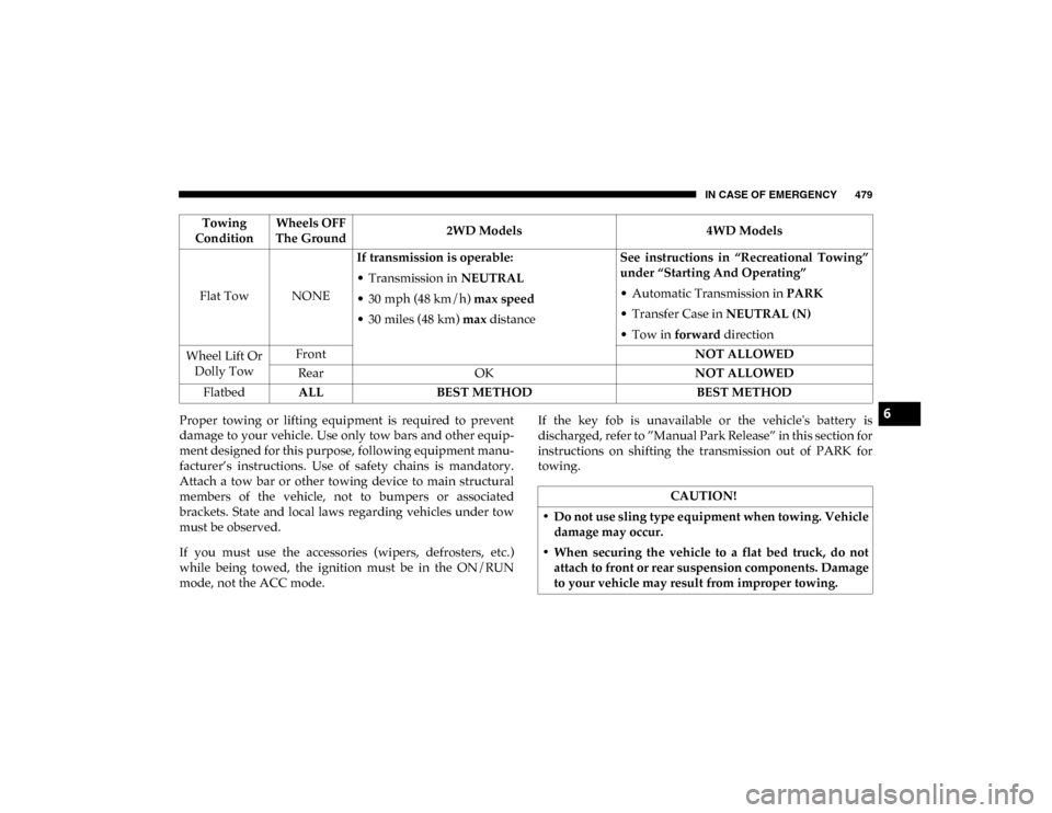
IN CASE OF EMERGENCY 479
Proper towing or lifting equipment is required to prevent
damage to your vehicle. Use only tow bars and other equip-
ment designed for this purpose, following equipment manu-
facturer’s instructions. Use of safety chains is mandatory.
Attach a tow bar or other towing device to main structural
members of the vehicle, not to bumpers or associated
brackets. State and local laws regarding vehicles under tow
must be observed.
If you must use the accessories (wipers, defrosters, etc.)
while being towed, the ignition must be in the ON/RUN
mode, not the ACC mode. If the key fob is unavailable or the vehicle's battery is
discharged, refer to ”Manual Park Release” in this section for
instructions on shifting the transmission out of PARK for
towing.
Towing
Condition Wheels OFF
The Ground 2WD Models
4WD Models
Flat Tow NONE If transmission is operable:
• Transmission in
NEUTRAL
• 30 mph (48 km/h) max speed
• 30 miles (48 km) max distance See instructions in “Recreational Towing”
under “Starting And Operating”
• Automatic Transmission in
PARK
• Transfer Case in NEUTRAL (N)
• Tow in forward direction
Wheel Lift Or Dolly Tow Front
NOT ALLOWED
Rear OK NOT ALLOWED
Flatbed ALL BEST METHOD BEST METHOD
CAUTION!
• Do not use sling type equipment when towing. Vehicle damage may occur.
• When securing the vehicle to a flat bed truck, do not attach to front or rear suspension components. Damage
to your vehicle may result from improper towing.
6
2020_DT_1500_OM_US.book Page 479
Page 567 of 674
MULTIMEDIA 565
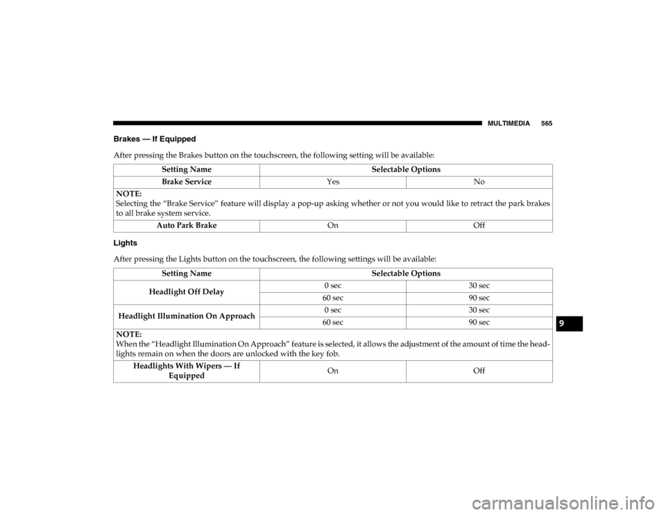
Brakes — If Equipped
After pressing the Brakes button on the touchscreen, the following setting will be available:
Lights
After pressing the Lights button on the touchscreen, the following settings will be available:Setting Name
Selectable Options
Brake Service YesNo
NOTE:
Selecting the “Brake Service” feature will display a pop-up asking whether or not you would like to retract the park brakes
to all brake system service. Auto Park Brake OnOff
Setting Name Selectable Options
Headlight Off Delay 0 sec
30 sec
60 sec 90 sec
Headlight Illumination On Approach 0 sec
30 sec
60 sec 90 sec
NOTE:
When the “Headlight Illumination On Approach” feature is selected, it allows the adjustment of the amount of time the head -
lights remain on when the doors are unlocked with the key fob.
Headlights With Wipers — If Equipped On
Off
9
2020_DT_1500_OM_US.book Page 565