stop start Ram 1500 2020 Owner's Manual
[x] Cancel search | Manufacturer: RAM, Model Year: 2020, Model line: 1500, Model: Ram 1500 2020Pages: 674, PDF Size: 32.69 MB
Page 8 of 674

6
STARTING AND OPERATING
STARTING THE ENGINE .............................................. 290
Automatic Transmission ............................................ 291
Tip Start Feature ......................................................... 291
Keyless Enter-N-Go — Ignition................................. 291
Normal Starting Using ENGINE START/STOP
Button ............................................................................ 292
Cold Weather Operation (Below –22°F Or
−30°C) ........................................................................... 296
After Starting................................................................ 296
ENGINE BLOCK HEATER — IF EQUIPPED .............. 296
ENGINE BREAK-IN RECOMMENDATIONS ............ 297
PARKING BRAKE ............................................................ 297
Electric Park Brake (EPB) ........................................... 297
AUTOMATIC TRANSMISSION ................................... 302
Ignition Park Interlock ................................................ 303
Brake/Transmission Shift Interlock System ........... 304
Eight-Speed Automatic Transmission ..................... 304
FOUR-WHEEL DRIVE OPERATION — IF
EQUIPPED ........................................................................ 310
Four-Position Electronically Shifted Transfer Case
(Eight Speed Transmission Only) — If
Equipped ...................................................................... 311
Five-Position Electronically Shifted Transfer Case
(Eight Speed Transmission Only) — If
Equipped ...................................................................... 314
ACTIVE-LEVEL FOUR CORNER AIR SUSPENSION
SYSTEM — IF EQUIPPED ...............................................319
Description.................................................................... 319
Air Suspension Modes ................................................322
Instrument Cluster Display Messages ......................323
Operation ......................................................................323
ACTIVE-LEVEL FOUR CORNER AIR SUSPENSION
SYSTEM (REBEL MODELS ONLY) — IF
EQUIPPED .........................................................................325
Description.................................................................... 325
Air Suspension Modes ................................................328
Instrument Cluster Display Messages ......................329
Operation ......................................................................329
AXLE LOCKER SYSTEM — IF EQUIPPED ..................331
LIMITED-SLIP DIFFERENTIAL — IF EQUIPPED ...... 332
POWER STEERING ..........................................................333
Electric Power Steering ..............................................333
FUEL SAVER TECHNOLOGY 5.7L ENGINES ONLY —
IF EQUIPPED .....................................................................333
STOP/START SYSTEM — IF EQUIPPED .....................334
Automatic Mode ..........................................................334
Possible Reasons The Engine Does Not
Autostop........................................................................334
To Start The Engine While In Autostop Mode ........335
2020_DT_1500_OM_US.book Page 6
Page 9 of 674

7
To Manually Turn Off The Stop Start System ......... 336
To Manually Turn On The Stop Start System ......... 337
System Malfunction .................................................... 337
SPEED CONTROL — IF EQUIPPED ............................. 337
To Activate ................................................................... 338
To Set A Desired Speed .............................................. 338
To Vary The Speed Setting ......................................... 338
To Accelerate For Passing ......................................... 340
To Resume Speed ....................................................... 340
To Deactivate ............................................................... 340
ADAPTIVE CRUISE CONTROL (ACC) — IF
EQUIPPED ......................................................................... 340
Adaptive Cruise Control (ACC) Operation............. 342
Activating Adaptive Cruise Control (ACC) ............ 343
To Activate/Deactivate .............................................. 344
To Set A Desired ACC Speed..................................... 345
To Cancel ...................................................................... 345
To Turn Off................................................................... 346
To Resume .................................................................... 346
To Vary The Speed Setting ......................................... 346
Setting The Following Distance In ACC .................. 348
Overtake Aid ................................................................ 351
ACC Operation At Stop.............................................. 351
Adaptive Cruise Control (ACC) Menu.....................352
Display Warnings And Maintenance .......................353
Precautions While Driving With ACC .....................355
General Information ....................................................358
Normal (Fixed Speed) Cruise Control Mode...........359
PARKSENSE FRONT AND REAR PARK ASSIST .......361
ParkSense Sensors........................................................363
ParkSense Warning Display.......................................363
ParkSense Display .......................................................363
Enabling And Disabling Front And/Or Rear
ParkSense ......................................................................368
Service The ParkSense Park Assist System ..............368
Cleaning The ParkSense System................................369
ParkSense System Usage Precautions.......................369
PARKSENSE ACTIVE PARK ASSIST SYSTEM — IF
EQUIPPED .........................................................................371
Enabling And Disabling The ParkSense Active Park
Assist System................................................................372
Parallel Parking Space Assistance Operation/
Display ..........................................................................373
Perpendicular Parking Space Assistance Operation/
Display ..........................................................................381
2020_DT_1500_OM_US.book Page 7
Page 11 of 674

9
FUSES.................................................................................. 444
External Power Distribution Center ........................ 445
Internal Power Distribution Center ......................... 449
JACKING AND TIRE CHANGING .............................. 454
Jack Location ................................................................ 454
Removal Of Jack And Tools ....................................... 455
Removing The Spare Tire ........................................... 458
Preparations For Jacking ............................................ 462
Jacking Instructions ..................................................... 463
To Stow The Flat Or Spare ........................................ 468
Reinstalling The Jack And Tools ............................... 470
JUMP STARTING ............................................................ 472
Preparations For Jump Start ...................................... 472
Jump Starting Procedure ............................................ 473
IF YOUR ENGINE OVERHEATS .................................. 475
MANUAL PARK RELEASE ............................................ 476
FREEING A STUCK VEHICLE ...................................... 477
TOWING A DISABLED VEHICLE ................................ 478
Two-Wheel Drive Models .......................................... 480
Four-Wheel Drive Models.......................................... 480
Emergency Tow Hooks — If Equipped ................... 481
ENHANCED ACCIDENT RESPONSE SYSTEM
(EARS) ................................................................................ 481
EVENT DATA RECORDER (EDR) ................................ 481
SERVICING AND MAINTENANCE
SCHEDULED SERVICING .............................................482
Maintenance Plan ........................................................483
Heavy Duty Use Of The Vehicle ...............................486
ENGINE COMPARTMENT ............................................487
3.6L Engine With Stop/Start .....................................487
5.7L Engine Without Stop/Start ................................488
5.7L Engine With Stop/Start ......................................489
Checking Oil Level ......................................................490
Adding Washer Fluid..................................................490
Maintenance-Free Battery .......................................... 491
Pressure Washing ........................................................491
DEALER SERVICE ........................................................... 492
Engine Oil — Gas Engine .......................................... 492
Engine Oil Filter ........................................................... 494
Engine Air Cleaner Filter ............................................494
Air Conditioner Maintenance ....................................496
Accessory Drive Belt Inspection ................................501
Body Lubrication .........................................................502
Windshield Wiper Blades ...........................................503
Exhaust System ........................................................... 505
Cooling System ........................................................... 506
2020_DT_1500_OM_US.book Page 9
Page 20 of 674

18 GETTING TO KNOW YOUR VEHICLE
KEYS
Key Fob
Your vehicle uses a keyless ignition system. The ignition
system consists of a key fob with Remote Keyless Entry
(RKE) and a START/STOP push button ignition system. The
Remote Keyless Entry system consists of a key fob and
Keyless Enter-N-Go feature.
NOTE:
• The key fob may not be found if it is located next to amobile phone, laptop or other electronic device; these
devices may block the key fob’s wireless signal.
• If your vehicle is equipped with a Wireless Charging Pad, the key fob may not be found if it is placed within 15 cm
(150 mm) of the pad. Refer to “Wireless Charging Pad—If
Equipped” in this chapter for further information.
The key fob allows you to lock or unlock all doors, tailgate,
and the RamBox (if equipped) as well as activate the Panic
Alarm from distances up to approximately 66 ft (20 m) using
a handheld key fob. The key fob does not need to be pointed
at the vehicle to activate the system. NOTE:
• In the ON/RUN position, all key fob buttons will work
until the vehicle reaches 2 mph (4 km/h).
• The key fob should not be placed next to the wireless charging pad (if equipped).
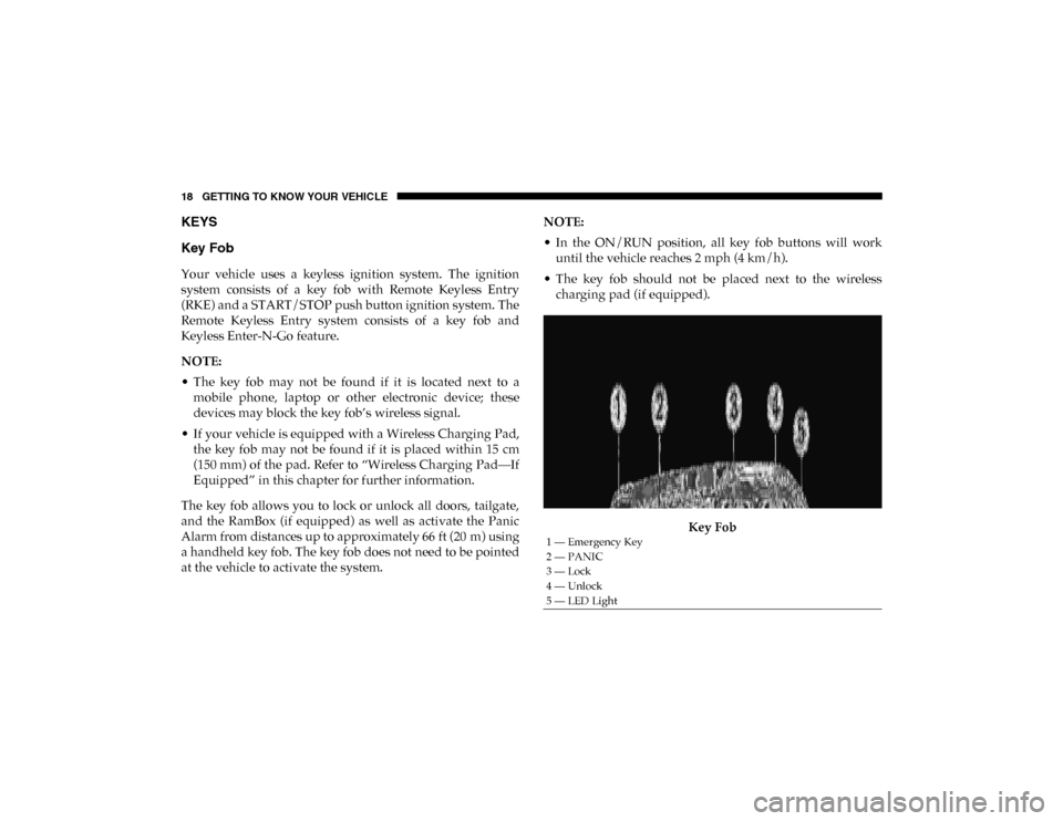
Key Fob
1 — Emergency Key
2 — PANIC
3 — Lock
4 — Unlock
5 — LED Light
2020_DT_1500_OM_US.book Page 18
Page 21 of 674

GETTING TO KNOW YOUR VEHICLE 19
In case the ignition switch does not change with the push of
a button, the key fob may have a low or fully depleted
battery. A low key fob battery can be verified by referring to
the instrument cluster, which will display directions to
follow.
NOTE:
A low key fob battery condition may be indicated by a
message in the instrument cluster display, or by the LED
light on the key fob. If the LED key fob light no longer illu-
minates from key fob button pushes, then the key fob battery
requires replacement.
In a situation where the battery is low or fully depleted, a
back up method can be used to operate the ignition switch.
Put the nose side of the key fob (side opposite of the emer-
gency key) against the START/STOP ignition button and
push to operate the ignition switch.
To Unlock The Doors And Tailgate
Push and release the unlock button on the key fob once to
unlock the driver’s door. Push the unlock button twice
within five seconds to unlock all doors, the tailgate and the
RamBox (if equipped). The turn signal lights will flash to
acknowledge the unlock signal. The illuminated entry
system will also turn on. NOTE:
The instrument cluster display or Uconnect Settings are
setup for driver door first, otherwise this will unlock all
doors.
To Lock The Doors And Tailgate
Push and release the lock button on the key fob to lock all
doors, the tailgate, and the RamBox (if equipped). The turn
signal lights will flash and the horn will chirp to acknowl
-
edge the signal.
Sound Horn With Remote Key Lock
This feature will cause the horn to chirp when the doors are
locked with the key fob. This feature can be turned on or
turned off.
NOTE:
Pushing the lock button on the key fob while you are in the
vehicle will activate the vehicle security alarm system.
Opening a door with the vehicle security alarm system acti -
vated will cause the alarm to sound. Push the unlock button
to deactivate the vehicle security alarm system.
Refer to “Instrument Cluster Display” in “Getting To Know
Your Instrument Panel” for further information.
2
2020_DT_1500_OM_US.book Page 19
Page 27 of 674

GETTING TO KNOW YOUR VEHICLE 25
Le présent appareil est conforme aux CNR d`Innovation,
Science and Economic Development applicables aux appar-
eils radio exempts de licence. L'exploitation est autorisée aux
deux conditions suivantes:
1. l'appareil ne doit pas produire de brouillage, et
2. l'utilisateur de l'appareil doit accepter tout brouillage radioélectrique subi, même si le brouillage est susceptible
d'en compromettre le fonctionnement.
La operación de este equipo está sujeta a las siguientes dos
condiciones:
1. es posible que este equipo o dispositivo no cause interfer -
encia perjudicial y
2. este equipo o dispositivo debe aceptar cualquier interfer- encia, incluyendo la que pueda causar su operación no
deseada.
NOTE:
Changes or modifications not expressly approved by the
party responsible for compliance could void the user’s
authority to operate the equipment.IGNITION SWITCH
Keyless Push Button Ignition
This feature allows the driver to operate the ignition switch
with the push of a button as long as the Remote Keyless
Entry key fob is in the passenger compartment.
The Keyless Push Button Ignition has four operating posi -
tions; three of which are labeled and will illuminate when in
position. The three positions are OFF, ACC, and ON/RUN.
The fourth position is START; during start RUN will illumi -
nate.
NOTE:
In case the ignition switch does not change with the push of
a button, the key fob may have a low or depleted battery. In
this situation, a back up method can be used to operate the
ignition switch. Put the nose side (side opposite of the emer -
gency key) of the key fob against the START/STOP ignition
button, with your foot applied on the brake pedal, and push
to operate the ignition switch.2
2020_DT_1500_OM_US.book Page 25
Page 28 of 674

26 GETTING TO KNOW YOUR VEHICLE
(Continued)
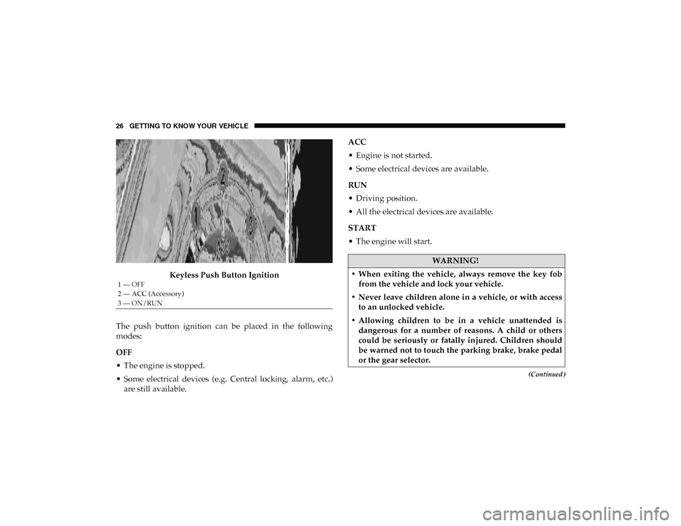
Keyless Push Button Ignition
The push button ignition can be placed in the following
modes:
OFF
• The engine is stopped.
• Some electrical devices (e.g. Central locking, alarm, etc.) are still available. ACC
• Engine is not started.
• Some electrical devices are available.
RUN
• Driving position.
• All the electrical devices are available.
START
• The engine will start.
1 — OFF
2 — ACC (Accessory)
3 — ON/RUN
WARNING!
• When exiting the vehicle, always remove the key fob from the vehicle and lock your vehicle.
• Never leave children alone in a vehicle, or with access to an unlocked vehicle.
• Allowing children to be in a vehicle unattended is dangerous for a number of reasons. A child or others
could be seriously or fatally injured. Children should
be warned not to touch the parking brake, brake pedal
or the gear selector.
2020_DT_1500_OM_US.book Page 26
Page 29 of 674

GETTING TO KNOW YOUR VEHICLE 27
The engine only runs in the ON/RUN ignition position or
from a remote start request.
In case the ignition switch does not change with the push of
a button, the key fob may have a low or dead battery. In this
situation, a back up method can be used to operate the igni-
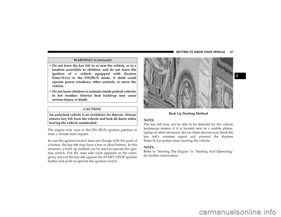
tion switch. Put the nose side (side opposite of the emer -
gency key) of the key fob against the START/STOP ignition
button and push to operate the ignition switch. Back Up Starting Method
NOTE:
The key fob may not be able to be detected by the vehicle
keyless-go system if it is located next to a mobile phone,
laptop or other electronic device; these devices may block the
key fob’s wireless signal and prevent the Keyless
Enter-N-Go system from starting the vehicle.
NOTE:
Refer to "Starting The Engine" in "Starting And Operating"
for further information.
• Do not leave the key fob in or near the vehicle, or in a
location accessible to children, and do not leave the
ignition of a vehicle equipped with Keyless
Enter-N-Go in the ON/RUN mode. A child could
operate power windows, other controls, or move the
vehicle.
• Do not leave children or animals inside parked vehicles in hot weather. Interior heat build-up may cause
serious injury or death.
CAUTION!
An unlocked vehicle is an invitation for thieves. Always
remove key fob from the vehicle and lock all doors when
leaving the vehicle unattended.
WARNING! (Continued)
2
2020_DT_1500_OM_US.book Page 27
Page 103 of 674

GETTING TO KNOW YOUR VEHICLE 101
5. Push and hold the close switch again within five secondsto begin the teaching process. The sunroof will complete
one full cycle and return to the fully closed position.
NOTE:
If the close switch is released anytime during the teach cycle,
the procedure will need to be repeated starting from the first
step.
6. Once the sunroof has stopped in the fully closed position, release the close switch. The sunroof is now reset and
ready to use.Dual Pane Power Sunroof — If Equipped
The power sunroof switches are located on the overhead
console between the courtesy/reading lights.
Power Sunroof Switches
1 — Opening/Closing Sunroof
2 — Venting Sunroof
3 — Opening/Closing Sunshade
2
2020_DT_1500_OM_US.book Page 101
Page 164 of 674

162 GETTING TO KNOW YOUR INSTRUMENT PANEL
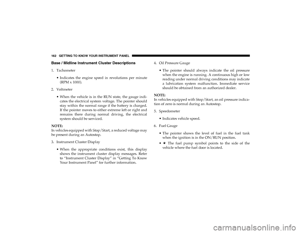
Base / Midline Instrument Cluster Descriptions
1. Tachometer• Indicates the engine speed in revolutions per minute(RPM x 1000).
2. Voltmeter
• When the vehicle is in the RUN state, the gauge indi -
cates the electrical system voltage. The pointer should
stay within the normal range if the battery is charged.
If the pointer moves to either extreme left or right and
remains there during normal driving, the electrical
system should be serviced.
NOTE:
In vehicles equipped with Stop/Start, a reduced voltage may
be present during an Autostop.
3. Instrument Cluster Display
• When the appropriate conditions exist, this displayshows the instrument cluster display messages. Refer
to “Instrument Cluster Display” in “Getting To Know
Your Instrument Panel” for further information. 4. Oil Pressure Gauge
• The pointer should always indicate the oil pressurewhen the engine is running. A continuous high or low
reading under normal driving conditions may indicate
a lubrication system malfunction. Immediate service
should be obtained from an authorized dealer.
NOTE:
In vehicles equipped with Stop/Start, an oil pressure indica -
tion of zero is normal during an Autostop.
5. Speedometer
• Indicates vehicle speed.
6. Fuel Gauge
• The pointer shows the level of fuel in the fuel tankwhen the ignition is in the ON/RUN position.
• The fuel pump symbol points to the side of the vehicle where the fuel door is located.
2020_DT_1500_OM_US.book Page 162