AIR DAM RAM 1500 2021 User Guide
[x] Cancel search | Manufacturer: RAM, Model Year: 2021, Model line: 1500, Model: RAM 1500 2021Pages: 496, PDF Size: 20.89 MB
Page 155 of 496

STARTING AND OPERATING153
If exceptional circumstances should make it
necessary to engage the parking brake while
the vehicle is in motion, maintain upward
pressure on the EPB switch for as long as
engagement is desired. The BRAKE telltale light
will illuminate, and a continuous chime will
sound. The rear stop lamps will also be
illuminated automatically while the vehicle
remains in motion.
To disengage the parking brake while the
vehicle is in motion, release the switch. If the
vehicle is brought to a complete stop using the
parking brake, when the vehicle reaches
approximately 3 mph, (5 km/h) the parking
brake will remain engaged. In the unlikely event of a malfunction of the EPB
system, a yellow EPB fault light will illuminate.
This may be accompanied by the BRAKE telltale
light flashing. In this event, urgent service of the
EPB system is required. Do not rely on the
parking brake to hold the vehicle stationary.
Auto Park Brake
The Electric Park Brake (EPB) can be
programmed to be applied automatically
whenever the vehicle is at a standstill and the
automatic transmission is placed in PARK. Auto
Park Brake is enabled and disabled by
customer selection through the customer
programmable features section of the Uconnect
Settings Ú
page 245.
Any single Auto Park Brake application can be
bypassed by pushing the EPB switch to the
release position while the transmission is
placed in PARK.
SafeHold
SafeHold is a safety feature of the Electric Park
Brake (EPB) system that will engage the parking
brake automatically if the vehicle is left
unsecured while the ignition is in ON/RUN. The parking brake will automatically engage if
all of the following conditions are met:
The vehicle is at a standstill.
There is no attempt to press the brake pedal
and accelerator pedal.
The seat belt is unbuckled.
The driver door is open.
SafeHold can be temporarily bypassed by
pushing the EPB switch while the driver door is
open. Once manually bypassed, SafeHold will
be enabled again once the vehicle reaches
12 mph (20 km/h) or the ignition is turned to
the OFF position and back to ON again.
Brake Service Mode
We recommend having your brakes serviced by
an authorized dealer. You should only make
repairs for which you have the knowledge and
the right equipment. You should only enter
Brake Service Mode during brake service.
When servicing your rear brakes, it may be
necessary for you or your technician to push the
rear piston into the rear caliper bore. With the
Electric Park Brake (EPB) system, this can only
be done after retracting the EPB actuator.
WARNING!
Driving the vehicle with the parking brake
engaged, or repeated use of the parking
brake to slow the vehicle may cause serious
damage to the brake system. Be sure the
parking brake is fully disengaged before
driving; failure to do so can lead to brake
failure and a collision.
4
21_DT_OM_EN_USC_t.book Page 153
Page 167 of 496
STARTING AND OPERATING165
NOTE:
Do not attempt to make a shift while only the
front or rear wheels are spinning. This could
cause damage to driveline components.
When operating your vehicle in 4WD Low, the
engine speed is approximately three times that
of the 2WD, 4WD Auto or 4WD High positions
at a given road speed. Take care not to
overspeed the engine and do not exceed
25 mph (40 km/h).
Proper operation of four-wheel drive vehicles
depends on tires of equal size, type and
circumference on each wheel. Any difference in
tire size can cause damage to the drivetrain.
Because four-wheel drive provides improved
traction, there is a tendency to exceed safe
turning and stopping speeds. Do not go faster
than road conditions permit.
Shifting Procedure
If any of the requirements to select a new
transfer case position have not been met,
then the transfer case will not shift. The posi -
tion indicator light for the previous position
will remain on and the newly selected posi -
tion indicator light will continue to flash until
all the requirements for the selected position
have been met.
If all the requirements to select a new
transfer case position have been met, then
the current position indicator light will turn off
and the selected position indicator light will
flash until the transfer case completes the
shift. When the shift is complete, the position
indicator light for the selected position will
stop flashing and remain on.
ACTIVE-LEVEL FOUR CORNER AIR
SUSPENSION SYSTEM — IF EQUIPPED
DESCRIPTION
The air suspension system provides full time
load leveling capability along with the benefit of
being able to adjust vehicle height by using the
toggle switch.
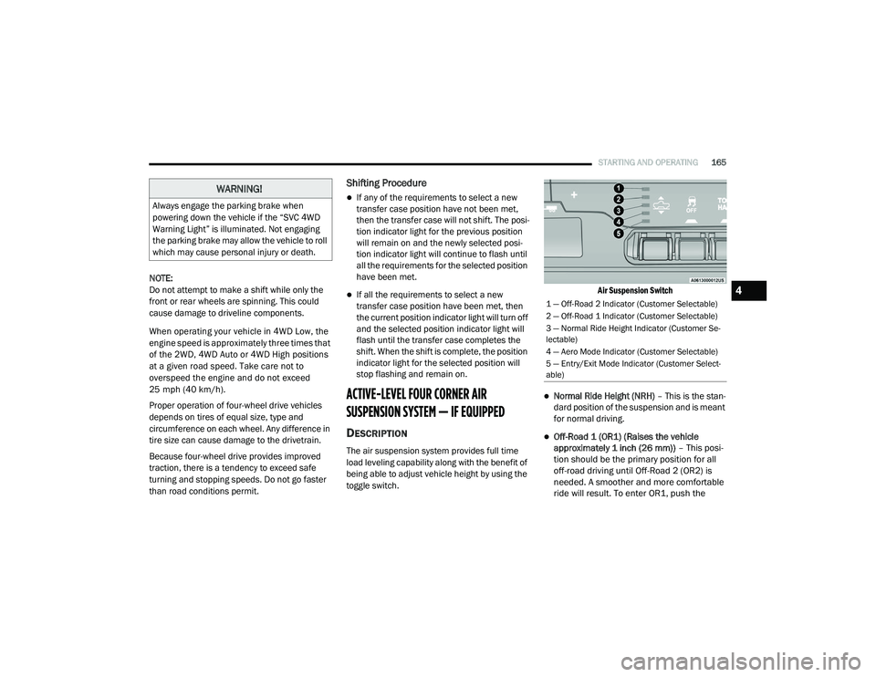
Air Suspension Switch
Normal Ride Height (NRH)
– This is the stan-
dard position of the suspension and is meant
for normal driving.
Off-Road 1 (OR1) (Raises the vehicle
approximately 1 inch (26 mm)) – This posi-
tion should be the primary position for all
off-road driving until Off-Road 2 (OR2) is
needed. A smoother and more comfortable
ride will result. To enter OR1, push the
WARNING!
Always engage the parking brake when
powering down the vehicle if the “SVC 4WD
Warning Light” is illuminated. Not engaging
the parking brake may allow the vehicle to roll
which may cause personal injury or death.
1 — Off-Road 2 Indicator (Customer Selectable)
2 — Off-Road 1 Indicator (Customer Selectable)
3 — Normal Ride Height Indicator (Customer Se -
lectable)
4 — Aero Mode Indicator (Customer Selectable)
5 — Entry/Exit Mode Indicator (Customer Select -
able)
4
21_DT_OM_EN_USC_t.book Page 165
Page 169 of 496

STARTING AND OPERATING167
to Normal Height Mode, push the height
selector switch up once while in Entry/Exit or
drive the vehicle over 15 mph (24 km/h).
Entry/Exit mode may not be available due to
vehicle payload, an instrument cluster
message will be displayed when this occurs
Úpage 114.
NOTE:
Entry/Exit mode may be achieved using your
key fob for easier entry/loading Ú page 17.
The system requires that the ignition be in the
ON/RUN position or the engine running for all
user requested changes. When lowering the
vehicle, all of the doors must be closed. If a door
is opened at any time while the vehicle is
lowering, the change will not be completed until
the open door(s) is closed. This system uses a lifting and lowering pattern
which keeps the headlights from incorrectly
shining into oncoming traffic. When raising the
vehicle, the rear of the vehicle will move up first
and then the front. When lowering the vehicle,
the front will move down first and then the rear.
After the engine is turned off, it may be noticed
that the air suspension system operates briefly;
this is normal. The system is correcting the
position of the vehicle to ensure a proper
appearance.
To assist with changing a spare tire, the air
suspension system has a feature which allows
the automatic leveling to be disabled
Ú
page 114.
NOTE:
If equipped with a touchscreen radio, all
enabling/disabling of air suspension features
must be done through the radio Ú page 237.AIR SUSPENSION MODES
The air suspension system has multiple modes
to protect the system in unique situations. The
engine should be running to change between
Air Suspension Modes.
Automatic AERO Mode
To improve aerodynamics, the air suspension
system has a feature which will put the vehicle
into AERO height automatically Úpage 114.
Automatic Aero Mode may be disabled through
vehicle settings in the Uconnect Radio (if
equipped) Ú page 237.
Tire Jack Mode
To assist with changing a tire, the air
suspension system has a feature which allows
the automatic leveling to be disabled
Ú page 237.
Transport Mode
For towing your vehicle with four wheels off the
road, the air suspension system has a feature
which will put the vehicle into Entry/Exit height
and disable the automatic load leveling system
Ú page 237.
CAUTION!
When in ENTRY/EXIT setting, be aware of your
surroundings, you may not have the
clearance required for certain areas and
vehicle damage may occur.
WARNING!
The air suspension system uses a high
pressure volume of air to operate the system.
To avoid personal injury or damage to the
system, see an authorized dealer for service.
4
21_DT_OM_EN_USC_t.book Page 167
Page 173 of 496

STARTING AND OPERATING171
This system uses a lifting and lowering pattern
which keeps the headlights from incorrectly
shining into oncoming traffic. When raising the
vehicle, the rear of the vehicle will move up first
and then the front. When lowering the vehicle,
the front will move down first and then the rear.
After the engine is turned off, it may be noticed
that the air suspension system operates briefly;
this is normal. The system is correcting the
position of the vehicle to ensure a proper
appearance.
To assist with changing a spare tire, the air
suspension system has a feature which allows
the automatic leveling to be disabled
Úpage 237.
NOTE:
If equipped with a touchscreen radio, all
enabling/disabling of air suspension features
must be done through the radio Ú page 237.AIR SUSPENSION MODES
The Air Suspension system has multiple modes
to protect the system in unique situations:
AERO Mode
To improve aerodynamics, the air suspension
system has a feature which will put the vehicle
into AERO height automatically Úpage 114.
Tire Jack Mode
To assist with changing a tire, the air
suspension system has a feature which allows
the automatic leveling to be disabled
Ú page 237.
Transport Mode
For towing your vehicle with four wheels off the
road, the air suspension system has a feature
which will put the vehicle into Entry/Exit height
and disable the automatic load leveling system
Ú page 237.
Wheel Alignment Mode
Before performing a wheel alignment, this
mode must be enabled Ú page 237.Protection Strategy
In order to “protect” the air suspension system,
the vehicle will disable load leveling as required
(suspension overloaded, battery charge low,
etc.). Load leveling will automatically resume as
soon as system operation requirements are
met. See an authorized dealer if system does
not resume.
NOTE:
For towing with air suspension Ú
page 214.
INSTRUMENT CLUSTER DISPLAY
M
ESSAGES
When the appropriate conditions exist, a
message will appear in the instrument cluster
display Ú page 114.
An audible chime will be heard whenever a
system error has been detected.
See an authorized dealer for system service if
normal operation does not resume.
WARNING!
The air suspension system uses a high
pressure volume of air to operate the system.
To avoid personal injury or damage to the
system, see an authorized dealer for service.
4
21_DT_OM_EN_USC_t.book Page 171
Page 212 of 496
210STARTING AND OPERATING
REFUELING THE VEHICLE — DIESEL ENGINE
The capless fuel filler is located on the left side
of the vehicle.
The capless system is sealed by two flapper
doors.
1. Put the vehicle in PARK and switch the
ignition off.
2. Open the fuel filler door.
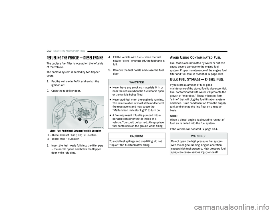
Diesel Fuel And Diesel Exhaust Fluid Fill Location
3. Insert the fuel nozzle fully into the filler pipe – the nozzle opens and holds the flapper
door while refueling. 4. Fill the vehicle with fuel – when the fuel
nozzle “clicks” or shuts off, the fuel tank is
full.
5. Remove the fuel nozzle and close the fuel door.
AVOID USING CONTAMINATED FUEL
Fuel that is contaminated by water or dirt can
cause severe damage to the engine fuel
system. Proper maintenance of the engine fuel
filter and fuel tank is essential Ú page 409.
BULK FUEL STORAGE — DIESEL FUEL
If you store quantities of fuel, good
maintenance of the stored fuel is also essential.
Fuel contaminated with water will promote the
growth of “microbes.” These microbes form
“slime” that will clog the fuel filtration system
and lines. Drain condensation from the supply
tank and change the line filter on a regular
basis.
NOTE:
When a diesel engine is allowed to run out of
fuel, air is pulled into the fuel system.
If the vehicle will not start Úpage 414.
1 — Diesel Exhaust Fluid (DEF) Fill Location
2 — Diesel Fuel Fill Location
WARNING!
Never have any smoking materials lit in or
near the vehicle when the fuel door is open
or the tank is being filled.
Never add fuel when the engine is running.
This is in violation of most state and federal
fire regulations and may cause the
“Malfunction Indicator Light” to turn on.
A fire may result if fuel is pumped into a
portable container that is inside of a
vehicle. You could be burned. Always place
fuel containers on the ground while filling.
CAUTION!
To avoid fuel spillage and overfilling, do not
“top off” the fuel tank after filling.
WARNING!
Do not open the high pressure fuel system
with the engine running. Engine operation
causes high fuel pressure. High pressure fuel
spray can cause serious injury or death.
21_DT_OM_EN_USC_t.book Page 210
Page 227 of 496

STARTING AND OPERATING225
Display Messages
The trailer brake control interacts with the
instrument cluster display. Display messages,
along with a single chime, will be displayed
when a malfunction is determined in the trailer
connection, trailer brake control, or on the
trailer Úpage 114. NOTE:
An aftermarket controller may be available
for use with trailers with air or elec
-
tric-over-hydraulic trailer brake systems. To
determine the type of brakes on your trailer
and the availability of controllers, check with
your trailer manufacturer or dealer.
Removal of the ITBM will cause errors and it
may cause damage to the electrical system
and electronic modules of the vehicle. See
your authorized dealer if an aftermarket
module is to be installed.
Towing Requirements — Trailer Lights And
Wiring
Whenever you pull a trailer, regardless of the
trailer size, stoplights and turn signals on the
trailer are required for motoring safety.
The Trailer Tow Package may include a four-pin
and seven-pin wiring harness. Use a factory
approved trailer harness and connector.
NOTE:
Do not cut or splice wiring into the vehicle’s
wiring harness. The electrical connections are all complete to
the vehicle but you must connect the harness to
a trailer connector. Refer to the following
illustrations.
NOTE:
Disconnect trailer wiring connector from the
vehicle before launching a boat (or any other
device plugged into vehicle’s electrical
connect) into water.
Be sure to reconnect once clear from water
area.
Four-Pin Connector
WARNING!
Connecting a trailer that is not compatible
with the ITBM system may result in reduced
or complete loss of trailer braking. There may
be a increase in stopping distance or trailer
instability which could result in personal
injury.
CAUTION!
Connecting a trailer that is not compatible
with the ITBM system may result in reduced
or complete loss of trailer braking. There may
be a increase in stopping distance or trailer
instability which could result in damage to
your vehicle, trailer, or other property.
1 — Ground
2 — Park
3 — Left Stop/Turn
4 — Right Stop/Turn
4
21_DT_OM_EN_USC_t.book Page 225
Page 231 of 496

STARTING AND OPERATING229
OVER THE ROAD OPERATION WITH
S
NOWPLOW ATTACHED
The blade restricts air flow to the radiator and
causes the engine to operate at higher than
normal temperatures. Therefore, when
transporting the plow, angle the blade
completely and position it as low as road or
surface conditions permit. Do not exceed
40 mph (64 km/h). The operator should always
maintain a safe stopping distance and allow
adequate passing clearance.
OPERATING TIPS
Under ideal snow plowing conditions, 20 mph
(32 km/h) should be maximum operating
speed. The operator should be familiar with the
area and surface to be cleaned. Reduce speed
and use extreme caution when plowing
unfamiliar areas or under poor visibility.
GENERAL MAINTENANCE
Snowplows should be maintained in
accordance with the plow manufacturer's
instructions.
Keep all snowplow electrical connections and
battery terminals clean and free of corrosion.
When plowing snow, to avoid transmission and
drivetrain damage, the following precautions
should be observed:
Operate with transfer case in 4WD Low when
plowing small or congested areas where
speeds are not likely to exceed 15 mph
(24 km/h). At higher speeds operate in 4WD
High.
Vehicles with automatic transmissions
should use 4WD Low when plowing deep or
heavy snow for extended periods of time to
avoid transmission overheating.
Do not shift the transmission unless the
engine has returned to idle and wheels have
stopped. Make a practice of stepping on the
brake pedal while shifting the transmission.
4
21_DT_OM_EN_USC_t.book Page 229
Page 232 of 496
230STARTING AND OPERATING
RECREATIONAL TOWING (BEHIND MOTORHOME)
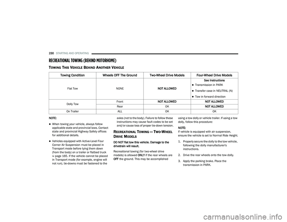
TOWING THIS VEHICLE BEHIND ANOTHER VEHICLE
NOTE:
When towing your vehicle, always follow
applicable state and provincial laws. Contact
state and provincial Highway Safety offices
for additional details.
Vehicles equipped with Active-Level Four
Corner Air Suspension must be placed in
Transport mode before tying them down
(from the body) on a trailer or flatbed truck
Úpage 165. If the vehicle cannot be placed
in Transport mode (for example, engine will
not run), tie-downs must be fastened to the axles (not to the body). Failure to follow these
instructions may cause fault codes to be set
and/or cause loss of proper tie-down tension.
RECREATIONAL TOWING — TWO-WHEEL
D
RIVE MODELS
DO NOT flat tow this vehicle. Damage to the
drivetrain will result.
Recreational towing (for two-wheel drive
models) is allowed ONLY if the rear wheels are
OFF the ground. This may be accomplished using a tow dolly or vehicle trailer. If using a tow
dolly, follow this procedure:
NOTE:
If vehicle is equipped with air suspension,
ensure the vehicle is set to Normal Ride Height.
1. Properly secure the dolly to the tow vehicle,
following the dolly manufacturer's
instructions.
2. Drive the rear wheels onto the tow dolly.
3. Apply the parking brake. Place the transmission in PARK.
Towing Condition Wheels OFF The Ground Two-Wheel Drive Models Four-Wheel Drive Models
Flat Tow NONENOT ALLOWED See InstructionsTransmission in PARK
Transfer case in NEUTRAL (N)
Tow in forward direction
Dolly Tow Front
NOT ALLOWED NOT ALLOWED
Rear OKNOT ALLOWED
On Trailer ALLOKOK
21_DT_OM_EN_USC_t.book Page 230
Page 234 of 496
232STARTING AND OPERATING
Shifting Into N (Neutral)
Use the following procedure to prepare your
vehicle for recreational towing.
1. Bring the vehicle to a complete stop on
level ground, with the engine running.
Apply the parking brake.
2. Press and hold the brake pedal.
3. Shift the transmission to NEUTRAL. The driver's door must be closed (or the driver's
seat belt buckled) so that the transmission
will remain in NEUTRAL when the brake
pedal is released.
NOTE:
If vehicle is equipped with air suspension,
ensure the vehicle is set to Normal Ride Height.
4. Using a ballpoint pen or similar object, push and hold the recessed transfer case N
(Neutral) button (at the center of the
transfer case switches). The N (Neutral)
indicator light will illuminate, and remain lit,
when the shift to N (Neutral) is complete.
After the shift is completed and the N
(Neutral) light stays on, release the N
(Neutral) button.
5. Release the parking brake. 6. Shift the transmission into REVERSE.
7. Release the brake pedal for five seconds
and ensure that there is no vehicle
movement.
8. Repeat steps 6 and 7 with the transmission in DRIVE.
9. Shift the transmission to NEUTRAL. Apply the parking brake. Turn off the engine. For
vehicles with Keyless Enter-N-Go, push and
hold the ENGINE START/STOP button until
the engine shuts off. The transmission will
automatically select PARK when the engine
is turned off.
10. Turn the ignition off.
11. Attach the vehicle to the tow vehicle using a suitable tow bar.
12. Turn the ignition to the ON/RUN mode, but do not start the engine.
13. Release the parking brake.
14. Turn the ignition OFF.
WARNING!
You or others could be injured or killed if you
leave the vehicle unattended with the transfer
case in the N (Neutral) position without first
fully engaging the parking brake. The transfer
case N (Neutral) position disengages both the
front and rear driveshafts from the power -
train and will allow the vehicle to roll, even if
the transmission is in PARK. The parking
brake should always be applied when the
driver is not in the vehicle.
CAUTION!
It is necessary to follow these steps to be cer -
tain that the transfer case is fully in N (Neu -
tral) before recreational towing to prevent
damage to internal parts.
21_DT_OM_EN_USC_t.book Page 232
Page 260 of 496
258MULTIMEDIA
SAFETY AND GENERAL INFORMATION
Safety Guidelines
Please read this manual carefully before using
the system. It contains instructions on how to
use the system in a safe and effective manner.
Do NOT attach any object to the touchscreen.
Doing so can result in damage to the
touchscreen.
Please read and follow these safety
precautions. Failure to do so may result in injury
or property damage.
Glance at the screen only when safe to do so.
If prolonged viewing of the screen is required,
park in a safe location and set the parking
brake.
Stop use immediately if a problem occurs.
Failure to do so may cause injury or damage
to the product. See an authorized dealer for
repair.
Ensure the volume level of the system is set
to a level that still allows you to hear outside
traffic and emergency vehicles.
Safe Usage Of The Uconnect System
The Uconnect system is a sophisticated elec -
tronic device. Do not let young children use
the system.
Permanent hearing loss may occur if you play
your music or sound system at loud volumes.
Exercise caution when setting the volume on
the system.
Keep drinks, rain and other sources of mois -
ture away from the system. Besides damage
to the system, moisture can cause electric
shocks as with any electronic device. NOTE:
Many features of this system are speed depen
-
dent. For your own safety, it is not possible to
use some of the touchscreen features while the
vehicle is in motion.
Care And Maintenance
Do not press the touchscreen with any hard
or sharp objects (pen, USB stick, jewelry,
etc.), which could scratch the surface.
Do not spray any liquid or chemicals directly
on the screen! Use a clean and dry microfiber
lens cleaning cloth in order to clean the
touchscreen.
If necessary, use a lint-free cloth dampened
with a cleaning solution, such as isopropyl
alcohol or an isopropyl alcohol and water
solution ratio of 50:50. Be sure to follow the
solvent manufacturer's precautions and
directions Ú page 482.
WARNING!
ALWAYS drive safely with your hands on the
steering wheel. You have full responsibility
and assume all risks related to the use of the
Uconnect features and applications in this
vehicle. Only use Uconnect when it is safe to
do so. Failure to do so may result in an
accident involving serious injury or death.
21_DT_OM_EN_USC_t.book Page 258