sensor RAM 1500 2021 Owner's Guide
[x] Cancel search | Manufacturer: RAM, Model Year: 2021, Model line: 1500, Model: RAM 1500 2021Pages: 496, PDF Size: 20.89 MB
Page 347 of 496
SAFETY345
On the other hand, depending on the type and
location of impact, front air bags may deploy in
crashes with little vehicle front-end damage but
that produce a severe initial deceleration.
Because air bag sensors measure vehicle
deceleration over time, vehicle speed and
damage by themselves are not good indicators
of whether or not an air bag should have
deployed.
Seat belts are necessary for your protection in
all collisions, and also are needed to help keep
you in position, away from an inflating air bag.
When the Occupant Restraint Controller (ORC)
detects a collision requiring the front air bags, it
signals the inflator units. A large quantity of
non-toxic gas is generated to inflate the front air
bags.
The steering wheel hub trim cover and the
upper passenger side of the instrument panel
separate and fold out of the way as the air bags
inflate to their full size. The front air bags fully
inflate in less time than it takes to blink your
eyes. The front air bags then quickly deflate
while helping to restrain the driver and front
passenger.Occupant Classification System (OCS) —
Front Passenger Seat
The OCS is part of a Federally regulated safety
system for this vehicle. It is designed to provide
Passenger Advanced Front Air Bag output
appropriate to the occupant’s seated weight, as
determined by the OCS.
The Occupant Classification System (OCS)
consists of the following:
Occupant Restraint Controller (ORC)
Occupant Classification Module (OCM) and
Sensor located in the front passenger seat
Air Bag Warning Light
Occupant Classification Module (OCM) And
Sensor
The Occupant Classification Module (OCM) is
located underneath the front passenger seat.
The Sensor is located beneath the passenger
seat cushion foam. Any weight on the seat will
be sensed by the Sensor. The OCM uses input
from the Sensor to determine the front
passenger’s most probable classification. The
OCM communicates this information to the ORC. The ORC may reduce the inflation rate of
the Passenger Advanced Front Air Bag
deployment based on occupant classification.
In order for the OCS to operate as designed, it is
important for the front passenger to be seated
properly and properly wearing the seat belt.
The OCS will NOT prevent deployment of the
Passenger Advanced Front Air Bag. The OCS
may reduce the inflation rate of the Passenger
Advanced Front Air Bag if the OCS estimates
that:
The front passenger seat is unoccupied or
has very light objects on it; or
The front passenger seat is occupied by a
small passenger, including a child; or
The front passenger seat is occupied by a
rear-facing child restraint; or
The front passenger is not properly seated or
his or her weight is taken off of the seat for a
period of time.
6
21_DT_OM_EN_USC_t.book Page 345
Page 353 of 496
SAFETY351
Side Impacts
The Side Air Bags are designed to activate in
certain side impacts. The Occupant Restraint
Controller (ORC) determines whether the
deployment of the Side Air Bags in a particular
impact event is appropriate, based on the
severity and type of collision. The side impact
sensors aid the ORC in determining the
appropriate response to impact events. The
system is calibrated to deploy the Side Air Bags
on the impact side of the vehicle during impacts
that require Side Air Bag occupant protection. In
side impacts, the Side Air Bags deploy
independently; a left side impact deploys the
left Side Air Bags only and a right-side impact
deploys the right Side Air Bags only. Vehicle
damage by itself is not a good indicator of
whether or not Side Air Bags should have
deployed.
The Side Air Bags will not deploy in all side
collisions, including some collisions at certain
angles, or some side collisions that do not
impact the area of the passenger compartment.
The Side Air Bags may deploy during angled or
offset frontal collisions where the front air bags
deploy. Side Air Bags are a supplement to the seat belt
restraint system. Side Air Bags deploy in less
time than it takes to blink your eyes.
NOTE:
Air bag covers may not be obvious in the interior
trim, but they will open during air bag deploy-
ment.
WARNING!
Occupants, including children, who are up
against or very close to Side Air Bags can be
seriously injured or killed. Occupants,
including children, should never lean on or
sleep against the door, side windows, or
area where the side air bags inflate, even if
they are in an infant or child restraint.
Seat belts (and child restraints where
appropriate) are necessary for your protec -
tion in all collisions. They also help keep
you in position, away from an inflating Side
Air Bag. To get the best protection from the
Side Air Bags, occupants must wear their
seat belts properly and sit upright with their
backs against the seats. Children must be
properly restrained in a child restraint or
booster seat that is appropriate for the size
of the child.
WARNING!
Side Air Bags need room to inflate. Do not
lean against the door or window. Sit upright
in the center of the seat.
Being too close to the Side Air Bags during
deployment could cause you to be severely
injured or killed.
Relying on the Side Air Bags alone could
lead to more severe injuries in a collision.
The Side Air Bags work with your seat belt
to restrain you properly. In some collisions,
Side Air Bags won’t deploy at all. Always
wear your seat belt even though you have
Side Air Bags.
6
21_DT_OM_EN_USC_t.book Page 351
Page 354 of 496
352SAFETY
Rollover Events
Side Air Bags and seat belt pretensioners are
designed to activate in certain rollover events.
The Occupant Restraint Controller (ORC)
determines whether deployment in a particular
rollover event is appropriate, based on the
severity and type of collision. Vehicle damage by
itself is not a good indicator of whether or not
Side Air Bags and seat belt pretensioners
should have deployed.
The Side Air Bags and seat belt pretensioners
will not deploy in all rollover events. The rollover
sensing system determines if a rollover event
may be in progress and whether deployment is
appropriate. In the event the vehicle
experiences a rollover or near rollover event,
and deployment is appropriate, the rollover
sensing system will deploy the side air bags and
seat belt pretensioners on both sides of the
vehicle.
The SABICs may help reduce the risk of partial
or complete ejection of vehicle occupants
through side windows in certain rollover or side
impact events.Air Bag System Components
NOTE:
The Occupant Restraint Controller (ORC) moni -
tors the internal circuits and interconnecting
wiring associated with electrical Air Bag System
Components listed below:
Occupant Restraint Controller (ORC)
Air Bag Warning Light
Steering Wheel and Column
Instrument Panel
Knee Impact Bolsters
Driver and Front Passenger Air Bags
Seat Belt Buckle Switch
Supplemental Side Air Bags
Front and Side Impact Sensors
Seat Belt Pretensioners
Seat Track Position Sensors
Occupant Classification System
If A Deployment Occurs
The front air bags are designed to deflate
immediately after deployment.
NOTE:
Front and/or side air bags will not deploy in all
collisions. This does not mean something is
wrong with the air bag system.
If you do have a collision which deploys the air
bags, any or all of the following may occur:
The air bag material may sometimes cause
abrasions and/or skin reddening to the occu -
pants as the air bags deploy and unfold. The
abrasions are similar to friction rope burns or
those you might get sliding along a carpet or
gymnasium floor. They are not caused by
contact with chemicals. They are not perma -
nent and normally heal quickly. However, if
you haven’t healed significantly within a few
days, or if you have any blistering, see your
doctor immediately.
As the air bags deflate, you may see some
smoke-like particles. The particles are a
normal by-product of the process that gener -
ates the non-toxic gas used for air bag infla -
tion. These airborne particles may irritate the
skin, eyes, nose, or throat. If you have skin or
21_DT_OM_EN_USC_t.book Page 352
Page 414 of 496

412SERVICING AND MAINTENANCE
(Continued)
Engine Air Cleaner Filter Installation
NOTE:
Inspect and clean the housing if dirt or debris is
present before replacing the engine air cleaner
filter.
1. Install the engine air cleaner filter into the housing assembly with the engine air
cleaner filter inspection surface facing
downward.
2. Install the engine air cleaner filter cover onto the housing assembly.
3. Tighten the fasteners (six) on the engine air cleaner filter assembly.
DRAINING FUEL/WATER SEPARATOR
F
ILTER — DIESEL ENGINE
The fuel/water separator filter housing is
located inside the frame rail, behind the left
front wheel. The best access to this water drain
valve is from under the vehicle. If water is detected in the water separator while
the engine is running, or while the ignition
switch is in the ON/RUN position, the “Water In
Fuel Indicator Light” will illuminate and an
audible chime will be heard. At this point, you
should stop the engine and drain the water from
the filter housing.
Fuel Filter Assembly
If the “Water In Fuel Indicator Light” comes on
and a single chime is heard while you are
driving, or with the ignition in the ON position,
there may be a problem with your water
separator wiring or sensor. See an authorized
dealer for service.
Upon proper draining of the water from the fuel
filter, the “Water In Fuel Indicator Light” will
remain illuminated for approximately 10
seconds. If the water was drained while the
engine was running, the “Water In Fuel Indicator
Light” may remain on for approximately three
minutes.
NOTE:
Care should be taken in disposing of used fluids
from your vehicle. Used fluids, indiscriminately
discarded, can present a problem to the envi
-
ronment. Contact an authorized dealer, service
station, or government agency for advice on
recycling programs and for where used fluids
and filters can be properly disposed of in your
area.
CAUTION!
Do not drain the fuel/water separator filter
when the engine is running.
Diesel fuel will damage blacktop paving
surfaces. Drain the filter into an appro-
priate container.
1 — Water In Fuel Drain Valve
CAUTION! (Continued)CAUTION!
If the “Water In Fuel Indicator Light” remains
on, DO NOT START the engine before you
drain water from the fuel filter to avoid engine
damage.
21_DT_OM_EN_USC_t.book Page 412
Page 431 of 496
SERVICING AND MAINTENANCE429
F06–10 Amp Red OUTPUT TO UPFITTER PDC — If Equipped
F07 ––Spare
F08 20 Amp Blue –Trailer Tow Backup
F09 –20 Amp Yellow Trailer Stop / Turn Lamp Left
F10 –20 Amp Yellow Trailer Stop / Turn Lamp Right
F11 –15 Amp Blue ID/CLEARANCE LIGHTS — If Equipped
F12 20 Amp Blue –Trailer Tow Park Lamp
F13 ––Spare
F14 –10 Amp Red AC Clutch
F15 –5 Amp Tan Intelligent Battery Sensor (IBS)
F16 ––Spare
F17 –20 Amp Yellow Air Suspension
F18 –15 Amp Blue AGS / Rear Axle Cooling Valve / Active Air Dam
F19 ––Spare
F20 –20 Amp Yellow Adjustable Pedals
F21 30 Amp Pink –Power Side Step
F22 50 Amp Red –Air Module
F23 ––Spare
F24 –20 Amp Yellow TCM SBW
F25 40 Amp Green –Exterior Lights 2
Cavity Cartridge Fuse Micro Fuse Description
8
21_DT_OM_EN_USC_t.book Page 429
Page 433 of 496

SERVICING AND MAINTENANCE431
F4630 Amp Pink –Fuel Heater
F47 30 Amp Pink –Rear Defroster
F48 ––Spare
F49 30 Amp Pink –Htr Ctrl (Diesel Only)
F50 20 Amp Blue –AUX SWITCH #6 — If Equipped
F51 25 Amp White –FUEL PUMP MOTOR #1 — If Equipped
F52 ––Spare
F53 –10 Amp Red Supply / Purging Pump – If Equipped
F54 –15 Amp Blue PCM
F55 –15 Amp Blue Right HID Headlamp
F56 ––Spare
F57 –20 Amp Yellow Horn
F58 25 Amp White –FUEL PUMP MOTOR #2 — If Equipped
F59 –25 Amp Clear Injectors / IGN Coil / Glow Plug Module
F60 –20 Amp Yellow ECM / PCM / ACT Short Running Valve
F61 –15 Amp Blue Left HID Headlamp / Spare
F62 60 Amp Blue
40 Amp Green –
Glow Plug (DSL) / LTR Coolant Pump (TRX)
F63 20 Amp Blue –NOx Sensor
F64 –10 Amp Red PM Sensor – If Equipped
CavityCartridge Fuse Micro Fuse Description
8
21_DT_OM_EN_USC_t.book Page 431
Page 437 of 496
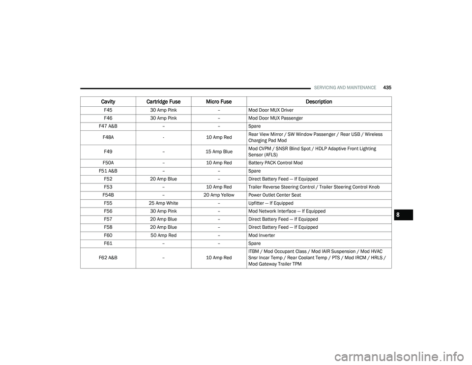
SERVICING AND MAINTENANCE435
F4530 Amp Pink –Mod Door MUX Driver
F46 30 Amp Pink –Mod Door MUX Passenger
F47 A&B ––Spare
F48A -10 Amp RedRear View Mirror / SW Window Passenger / Rear USB / Wireless
Charging Pad Mod
F49 –15 Amp BlueMod CVPM / SNSR Blind Spot / HDLP Adaptive Front Lighting
Sensor (AFLS)
F50A –10 Amp Red Battery PACK Control Mod
F51 A&B ––Spare
F52 20 Amp Blue –Direct Battery Feed — If Equipped
F53 –10 Amp Red Trailer Reverse Steering Control / Trailer Steering Control Knob
F54B –20 Amp Yellow Power Outlet Center Seat
F55 25 Amp White –Upfitter — If Equipped
F56 30 Amp Pink –Mod Network Interface — If Equipped
F57 20 Amp Blue –Direct Battery Feed — If Equipped
F58 20 Amp Blue –Direct Battery Feed — If Equipped
F60 50 Amp Red –Mod Inverter
F61 ––Spare
F62 A&B –10 Amp RedITBM / Mod Occupant Class / Mod IAIR Suspension / Mod HVAC
Snsr Incar Temp / Rear Coolant Temp / PTS / Mod IRCM / HRLS /
Mod Gateway Trailer TPM
Cavity
Cartridge Fuse Micro Fuse Description
8
21_DT_OM_EN_USC_t.book Page 435
Page 453 of 496

SERVICING AND MAINTENANCE451
cold tire inflation pressure must not exceed the
maximum inflation pressure molded into the
tire sidewall.
Check tire pressures more often if subject to a
wide range of outdoor temperatures, as tire
pressures vary with temperature changes.
Tire pressures change by approximately 1 psi
(7 kPa) per 12°F (7°C) of air temperature
change. Keep this in mind when checking tire
pressure inside a garage, especially in the
Winter.
Example: If garage temperature = 68°F (20°C)
and the outside temperature = 32°F (0°C) then
the cold tire inflation pressure should be
increased by 3 psi (21 kPa), which equals 1 psi
(7 kPa) for every 12°F (7°C) for this outside
temperature condition.
Tire pressure may increase from 2 to 6 psi
(13 to 40 kPa) during operation. DO NOT reduce
this normal pressure build up or your tire
pressure will be too low.
Tire Pressures For High Speed Operation
The manufacturer advocates driving at safe
speeds and within posted speed limits. Where
speed limits or conditions are such that the
vehicle can be driven at high speeds, maintaining correct tire inflation pressure is
very important. Increased tire pressure and
reduced vehicle loading may be required for
high-speed vehicle operation. Refer to an
authorized tire dealer or original equipment
vehicle dealer for recommended safe operating
speeds, loading and cold tire inflation
pressures.
Radial Ply Tires
Tire Repair
If your tire becomes damaged, it may be
repaired if it meets the following criteria:
The tire has not been driven on when flat
The damage is only on the tread section of
your tire (sidewall damage is not repairable)
The puncture is no greater than a ¼ of an
inch (6 mm)
Consult an authorized tire dealer for tire repairs
and additional information.
Damaged Run Flat tires, or Run Flat tires that
have experienced a loss of pressure should be
replaced immediately with another Run Flat tire
of identical size and service description (Load
Index and Speed Symbol). Replace the tire
pressure sensor as well as it is not designed to
be reused.
Run Flat Tires — If Equipped
Run Flat tires allow you the capability to drive
50 miles (80 km) at 50 mph (80 km/h) after a
rapid loss of inflation pressure. This rapid loss
of inflation is referred to as the Run Flat mode.
A Run Flat mode occurs when the tire inflation
pressure is of/or below 14 psi (96 kPa). Once a
Run Flat tire reaches the Run Flat mode it has
WARNING!
High speed driving with your vehicle under
maximum load is dangerous. The added
strain on your tires could cause them to fail.
You could have a serious collision. Do not
drive a vehicle loaded to the maximum
capacity at continuous speeds above 75 mph
(120 km/h).
WARNING!
Combining radial ply tires with other types of
tires on your vehicle will cause your vehicle to
handle poorly. The instability could cause a
collision. Always use radial ply tires in sets of
four. Never combine them with other types of
tires.
8
21_DT_OM_EN_USC_t.book Page 451
Page 454 of 496

452SERVICING AND MAINTENANCE
limited driving capabilities and needs to be
replaced immediately. A Run Flat tire is not
repairable. When a Run Flat tire is changed
after driving with underinflated tire condition,
please replace the TPM sensor as it is not
designed to be reused when driven under Run
Flat mode 14 psi (96 kPa) condition.
NOTE:
TPM Sensor must be replaced after driving the
vehicle on a flat tire condition.
It is not recommended driving a vehicle loaded
at full capacity or to tow a trailer while a tire is in
the Run Flat mode.
For more information Úpage 327.
Tire Spinning
When stuck in mud, sand, snow, or ice
conditions, do not spin your vehicle's wheels
above 30 mph (48 km/h) or for longer than
30 seconds continuously without stopping.
For further information Ú page 391.
Tread Wear Indicators
Tread wear indicators are in the original
equipment tires to help you in determining
when your tires should be replaced.
Tire Tread
These indicators are molded into the bottom of
the tread grooves. They will appear as bands
when the tread depth becomes a 1/16 of an
inch (1.6 mm). When the tread is worn to the
tread wear indicators, the tire should be
replaced.
For further information Ú
page 453.
Life Of Tire
The service life of a tire is dependent upon
varying factors including, but not limited to:
Driving style
Tire pressure - Improper cold tire inflation
pressures can cause uneven wear patterns
to develop across the tire tread. These
abnormal wear patterns will reduce tread life,
resulting in the need for earlier tire replace -
ment
Distance driven
Performance tires, tires with a speed rating of
V or higher, and Summer tires typically have
a reduced tread life. Rotation of these tires
per the vehicle scheduled maintenance is
highly recommended
WARNING!
Fast spinning tires can be dangerous. Forces
generated by excessive wheel speeds may
cause tire damage or failure. A tire could
explode and injure someone. Do not spin your
vehicle's wheels faster than 30 mph (48 km/h)
for more than 30 seconds continuously when
you are stuck, and do not let anyone near a
spinning wheel, no matter what the speed.
1 — Worn Tire
2 — New Tire
21_DT_OM_EN_USC_t.book Page 452
Page 489 of 496

487
J
Jack Location
................................................. 377Jump Starting................................................ 386
K
Key Fob Programming Additional Key Fobs
.............. 20Key Fob Battery Service (Remote Keyless
Entry)............................................................... 18Key Fob Programming (Remote Keyless
Entry)............................................................... 20Keyless Enter-N-Go................................. 28, 143Passive Entry............................................... 28Keys................................................................. 17
L
Lane Change And Turn Signals........................ 55Lane Change Assist......................................... 55LaneSense.................................................... 199Lap/Shoulder Belts....................................... 336Latches.......................................................... 371Hood........................................................... 84Lead Free Gasoline........................................ 468Leaks, Fluid................................................... 371Life Of Tires................................................... 452Light Bulbs........................................... 371, 437
Lights............................................................ 371Air Bag.................................... 126, 342, 369Brake Assist Warning............................... 314Brake Warning.......................................... 126Bulb Replacement.................................... 437Cargo........................................................... 56Center Mounted Stop............................... 442Courtesy/Reading....................................... 57Cruise....................................................... 136Daytime Running......................................... 53Electronic Stability Program (ESP)Indicator............................................... 128Exterior...............................................52, 371Fog........................................................... 441Hazard Warning Flasher........................... 373Headlights............................................ 52, 54High Beam................................................... 53High Beam/Low Beam Select...................... 53Hill Descent Control Indicator................... 315Illuminated Entry......................................... 58Interior......................................................... 57Lights On Reminder..................................... 55Low Fuel................................................... 131Malfunction Indicator (Check Engine)....... 130Park.......................................................... 135Passing........................................................ 54
Seat Belt Reminder.................................. 126Security Alarm.......................................... 127Service...................................................... 437Traction Control........................................ 314Turn Signals............55, 136, 371, 439, 441Warning Instrument ClusterDescriptions................................ 128, 136Limited-Slip Differential....................... 174, 427Load Shed Battery Saver Mode..................... 125Load Shed Battery Saver On......................... 125Load Shed Electrical Load Reduction........... 125Load Shed Intelligent Battery Sensor............ 125Loading Vehicle............................................. 213Tires.......................................................... 447LocksAutomatic Door............................................30Child Protection...........................................31Power Door..................................................28Low Tire Pressure System............................. 327Lubrication, Body.......................................... 418Lug Nuts........................................................ 467Lug Nuts/Bolts.............................................. 467
M
Maintenance.............................................81, 84Maintenance Free Battery............................ 409Maintenance Schedule............... 395, 399, 40011
21_DT_OM_EN_USC_t.book Page 487