display RAM 1500 2021 Manual Online
[x] Cancel search | Manufacturer: RAM, Model Year: 2021, Model line: 1500, Model: RAM 1500 2021Pages: 496, PDF Size: 20.89 MB
Page 207 of 496

STARTING AND OPERATING205
If the camera delay is turned off, the camera
image will close and display the previous screen
after shifting out of REVERSE.
If active guidelines are enabled, the lines are
overlaid on the image in the Rear View to
illustrate the width of the vehicle. The view will
also include the side view mirrors and its
projected back up path based on the steering
wheel position.
There are different colored zones to indicate the
distance to the rear of the vehicle. Refer to the
chart below:
Modes Of Operation
Standard Rear View can be manually activated
by selecting “Back Up Camera” through the
Controls menu within the Uconnect system. Top View
The Top View will show in the Uconnect system
with Rear View and Front View in a split screen
display. There are integrated ParkSense arcs in
the image at the front and rear of the vehicle.
The arcs will change color from yellow to red
corresponding the distance zones to the
oncoming object.
Surround View Camera View
NOTE:
Front tires will be seen in the image when the
tires are turned.
Due to wide angle cameras in the mirrors, the
image will appear distorted.
The Top View will show which doors are open.
Open front doors will block the outside
image.
Rear View This is the default view of the system
in REVERSE and is always paired with
the Top View of the vehicle with
optional active guidelines for the
projected path when enabled.
Rear Cross Path View Pressing the Rear Cross Path soft key
will give the driver a wider angle view
of the rear camera system. The Top
View will be disabled when this is
selected.
Front View The Front View will show you what is
immediately in front of the vehicle
and is always paired with the Top View
of the vehicle.
Zone
Distance To The Rear
Of The Vehicle
Red 0 - 1 ft (0 - 30 cm)
Yellow 1 ft - 6.5 ft
(30 cm - 2 m)
Green 6.5 ft or greater
(2 m or greater)
4
21_DT_OM_EN_USC_t.book Page 205
Page 208 of 496
206STARTING AND OPERATING
Front Cross Path View
Pressing the Front Cross Path soft key
will give the driver a wider angle view
of the front camera system. The Top
View will be disabled when this is
selected.
Rear View Camera Pressing the Back Up Camera soft key
will provide a full screen rear view with
Zoom View.
NOTE:
If the Rear View Camera view was selected
through the Surround View Camera menu,
exiting out of the Rear View screen will return to
the Surround View menu. If the Back Up Camera
was manually activated through the Controls
menu of the Uconnect system, exiting out of the
display screen will return to the Controls menu.
Zoom View
When the Rear View Camera image is being
displayed, and the vehicle speed is below
8 mph (13 km/h) while in any gear, Zoom View
is available. By pressing the “magnifying glass”
icon in the upper left of the display screen, the
image will zoom in to four times the standard view. Pressing the icon a second time will return
the view to the standard Back Up Camera
display.
When Zoom View is selected while the vehicle is
in REVERSE, then shifted to DRIVE, the camera
delay view will display the standard Back Up
Camera view. If the vehicle is then returned to
REVERSE gear from DRIVE, the Zoom View
selection will automatically resume.
Shifting to NEUTRAL from any gear will maintain
the selected view (Zoom or Standard) as long as
the vehicle is below 8 mph (13 km/h).
If the vehicle is in PARK, Zoom View is available
until the gear selector is placed in DRIVE or
REVERSE and speeds are at or above 8 mph
(13 km/h).
NOTE:
If the vehicle is in DRIVE, NEUTRAL, or
REVERSE, and speed is greater than or equal
to 8 mph (13 km/h), Zoom View is unavail
-
able and the icon will appear grey.
While in Zoom View, the guidelines will not be
visible. Deactivation
The system is deactivated in the following
conditions if it was activated
automatically:
When the vehicle is shifted out of REVERSE
(with camera delay turned on), the camera
image will continue to be displayed for up to
10 seconds after shifting out of REVERSE
unless the vehicle speed exceeds 8 mph
(13 km/h), the vehicle is shifted into PARK or
the ignition is placed in the OFF position.
There is a touchscreen button “X” to disable
the display of the camera image.
When the vehicle is shifted out of REVERSE
(with camera delay turned off), the Surround
View Camera mode is exited and the last
known screen appears again.
The system is deactivated in the following
conditions if it was activated manually from the
Uconnect controls menu via Surround View
button or Back Up Camera button:
The “X” button on the display is pressed
Vehicle is shifted into PARK
Ignition is placed in the OFF position
Vehicle speed is over 8 mph (13 km/h) for
10 seconds
21_DT_OM_EN_USC_t.book Page 206
Page 209 of 496
STARTING AND OPERATING207
NOTE:
If the Surround View Camera is activated manu -
ally, and the vehicle is shifted into REVERSE,
deactivation methods for automatic activation
are assumed.
The camera delay system is turned off manually
through the Uconnect settings menu
Ú page 237.
NOTE:
If snow, ice, mud, or any foreign substance
builds up on the camera lenses, clean the
lenses, rinse with water, and dry with a soft
cloth. Do not cover the lenses.
If a malfunction with the system has
occurred, see an authorized dealer.
Forward Facing Camera With Tire Lines — If
Equipped
The Forward Facing Camera displays a front
view image of the road ahead, along with tire
lines to guide the driver when driving on narrow
roads. Tire lines can be activated/deactivated
through the Uconnect settings. Activation
The Forward Facing Camera can be activated in
the following ways:
Pressing the Forward Facing Camera button
in the Controls screen or Apps menu
Pressing the Backup Camera or Surround
View Camera button (if equipped) on the
touchscreen, followed by the AUX button
located in the upper left corner of the rear
-
view display
Pressing the Forward Facing Camera button
while the vehicle is in REVERSE
Once activated, the camera image will remain
on as long as the vehicle speed is below 8 mph
(13 km/h) and the vehicle is not in 4WD Low.
Deactivation
The Forward Facing Camera is deactivated in
the following conditions:
The vehicle is not in 4WD Low and the vehicle
speed exceeds 8 mph (13 km/h) for 10
seconds.
The “X” button on the display is pressed.
The vehicle is shifted into PARK.
The ignition is placed in the OFF position.
NOTE:
If the vehicle is in 4WD Low, the Forward Facing
Camera image will be displayed until the “X”
button is pressed or the ignition is placed in the
OFF position.
WARNING!
Drivers must be careful when backing up
even when using the Surround View Camera.
Always check carefully behind your vehicle,
and be sure to check for pedestrians,
animals, other vehicles, obstructions, or blind
spots before backing up. You are responsible
for the safety of your surroundings and must
continue to pay attention while backing up.
Failure to do so can result in serious injury or
death.
4
21_DT_OM_EN_USC_t.book Page 207
Page 210 of 496
208STARTING AND OPERATING
AUX CAMERA — IF EQUIPPED
Your vehicle may be equipped with one or two
AUX Cameras, which display images from the
trailer on the touchscreen.
Activation
The AUX Camera is activated any of the
following ways:
By first pressing the Backup Camera or
Surround View Camera (if equipped) button
on the touchscreen, followed by the AUX
button located in the upper left corner of the
rearview display
Pressing the AUX button in the Apps menu
Pressing the AUX button when the vehicle is
in REVERSE
If equipped with two AUX Cameras, you can
switch between each camera by pressing the
AUX1 or AUX2 buttons on the Trailer Camera
display. AUX1 Camera Button
AUX2 Camera Button
Deactivation
The AUX Camera is deactivated when the
following situations occur:
The “X” in the upper right corner of the touch -
screen is pressed. This will return the display
back to the previously displayed screen.
The vehicle speed exceeds 8 mph (13 km/h)
for 10 seconds.
The vehicle is shifted into PARK.
The ignition is placed in the OFF position. NOTE:
If the AUX button is pressed and no AUX
Camera is connected, the touchscreen will
display a blue screen along with the message
“Camera System Unavailable.” The screen
can be exited out by pressing the “X” in the
upper right hand corner. This will return the
display back to the previously displayed
screen.
Zoom View is not available with the AUX
Camera feature.
The display will always default to the Trailer
Camera display (AUX 1).
REFUELING THE VEHICLE — GASOLINE
ENGINE
The capless fuel filler is located on the left side
of the vehicle.
The capless system is sealed by two flapper
doors.
CAUTION!
To avoid vehicle damage, Surround View
should only be used as a parking aid. The
Surround View camera is unable to view
every obstacle or object in your drive path.
To avoid vehicle damage, the vehicle must
be driven slowly when using Surround View
to be able to stop in time when an obstacle
is seen. It is recommended that the driver
look frequently over his/her shoulder when
using Surround View.
21_DT_OM_EN_USC_t.book Page 208
Page 213 of 496
STARTING AND OPERATING211
DIESEL EXHAUST FLUID
Your vehicle is equipped with a Selective
Catalytic Reduction (SCR) system to meet diesel
emissions standards required by the
Environmental Protection Agency.
The purpose of the SCR system is to reduce
levels of oxides of nitrogen (NO
x) emitted from
engines that are harmful to our health and the
environment to a near-zero level. A small
quantity of Diesel Exhaust Fluid (DEF) is
injected into the exhaust upstream of a catalyst
where, when vaporized, converts smog-forming
NO
x into harmless nitrogen (N2) and water
vapor (H
2O), two natural components of the air
we breathe.
DIESEL EXHAUST FLUID STORAGE
Diesel Exhaust Fluid (DEF) is considered a very
stable product with a long shelf life. If DEF is
kept in temperatures between 10° and 90°F
(-12° and 32°C), it will last a minimum of one
year.
DEF may freeze at temperatures at or below
12°F (-11°C). The system has been designed to
operate in this environment. NOTE:
When working with DEF, it is important to know
that:
Any containers or parts that come into
contact with DEF must be DEF compatible
(plastic or stainless steel). Copper, brass,
aluminum, iron or non-stainless steel should
be avoided as they are subject to corrosion
by DEF.
If DEF is spilled, it should be wiped up
completely.
ADDING DIESEL EXHAUST FLUID
The Diesel Exhaust Fluid (DEF) gauge (located
on the instrument cluster) will display the level
of DEF remaining in the tank Ú
page 109.
NOTE:
Driving conditions (altitude, vehicle speed,
load, etc.) will effect the amount of DEF that
is used in your vehicle.
Outside temperature can affect DEF
consumption. In cold conditions, 12°F
(-11°C) and below, the DEF gauge may take
longer to operate as intended. This is a
normal function of the system.
There is an electric heater inside the DEF
tank that automatically works when neces -
sary. And if the DEF supply does freeze, the
truck will operate normally until it thaws.
Diesel Exhaust Fluid (DEF) Fill Procedure
NOTE:
For the correct fluid type Ú page 475.
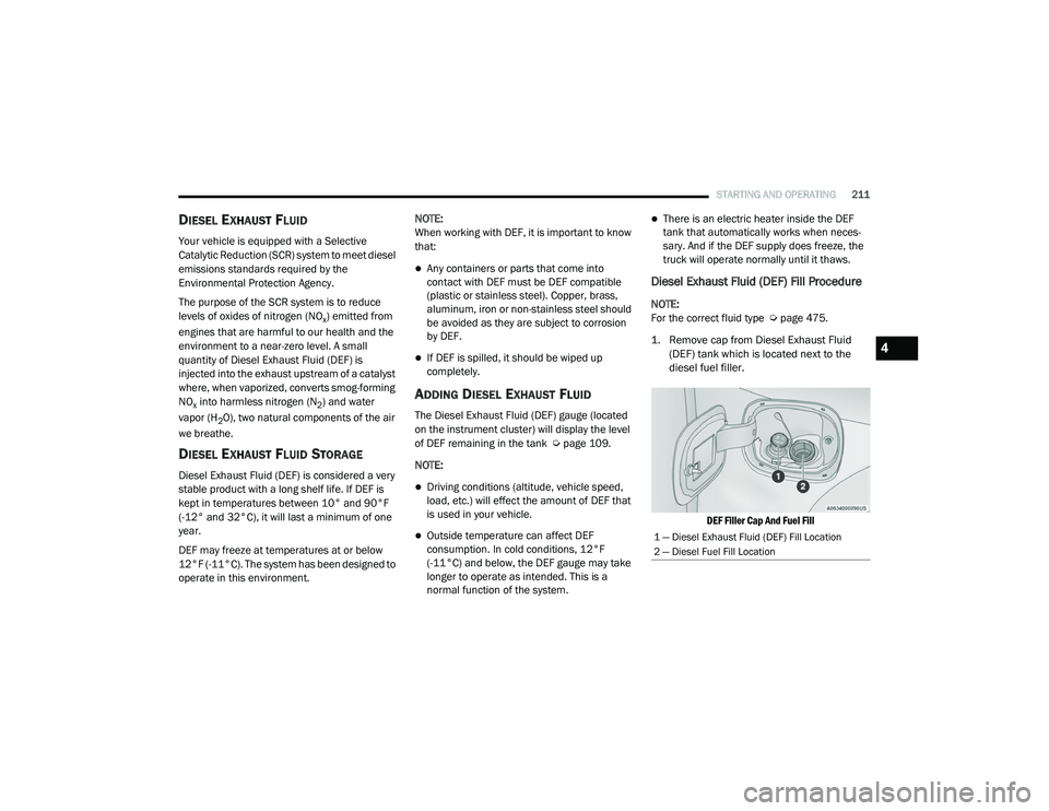
1. Remove cap from Diesel Exhaust Fluid (DEF) tank which is located next to the
diesel fuel filler.
DEF Filler Cap And Fuel Fill
1 — Diesel Exhaust Fluid (DEF) Fill Location
2 — Diesel Fuel Fill Location
4
21_DT_OM_EN_USC_t.book Page 211
Page 214 of 496

212STARTING AND OPERATING
(Continued)
(Continued)
2. Insert DEF fill adapter/nozzle into DEF tank filler neck.
NOTE:
The DEF gauge may take up to five seconds
to update after adding a gallon or more of
(DEF) to the DEF tank. If you have a fault
related to the DEF system, the gauge may not
update to the new level. See an authorized
dealer for service.
The DEF gauge may also not immediately
update after a refill if the temperature of the
DEF fluid is below 12°F (-11°C). The DEF line
heater will possibly warm up the DEF fluid
and allow the gauge to update after a period
of run time. Under very cold conditions, it is
possible that the gauge may not reflect the
new fill level for several drives.
Refilling With Nozzles
You can fill up at any DEF distributor.
Proceed as follows:
Insert the DEF nozzle in the filler, start
refilling and stop refilling at the first
shut-off (the shut-off indicates that the
DEF tank is full). Do not proceed with the
refilling, to prevent spillage of DEF.
Extract the nozzle. Refilling With Containers
Proceed as follows:
Check the expiration date.
Read the advice for use on the label
before pouring the content of the bottle
into the DEF tank.
If systems which cannot be screwed in
(e.g. tanks) are used for refilling, after the
indication appears on the instrument
panel display Ú
page 114 fill the DEF
tank with no more than 2 Gallons (8
liters).
If containers which can be screwed to the
filler are used, the reservoir is full when
the DEF level in the container stops
pouring out. Do not proceed further.
CAUTION!
To avoid DEF spillage, and possible
damage to the DEF tank from overfilling, do
not “top off” the DEF tank after filling.
DO NOT OVERFILL. DEF will freeze below
12ºF (-11ºC). The DEF system is designed
to work in temperatures below the DEF
freezing point, however, if the tank is over -
filled and freezes, the system could be
damaged.
When DEF is spilled, clean the area imme -
diately with water and use an absorbent
material to soak up the spills on the ground.
Do not attempt to start your engine if DEF is
accidentally added to the diesel fuel tank
as it can result in severe damage to your
engine, including but not limited to failure
of the fuel pump and injectors.
CAUTION! (Continued)
21_DT_OM_EN_USC_t.book Page 212
Page 222 of 496
220STARTING AND OPERATING
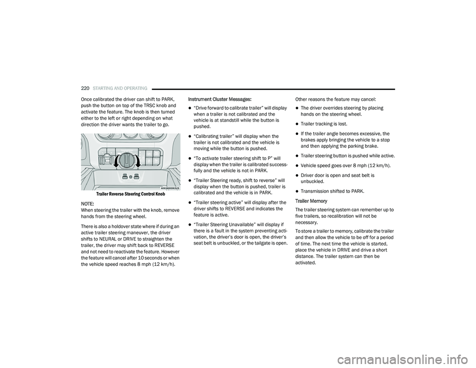
Once calibrated the driver can shift to PARK,
push the button on top of the TRSC knob and
activate the feature. The knob is then turned
either to the left or right depending on what
direction the driver wants the trailer to go.
Trailer Reverse Steering Control Knob
NOTE:
When steering the trailer with the knob, remove
hands from the steering wheel.
There is also a holdover state where if during an
active trailer steering maneuver, the driver
shifts to NEURAL or DRIVE to straighten the
trailer, the driver may shift back to REVERSE
and not need to reactivate the feature. However
the feature will cancel after 10 seconds or when
the vehicle speed reaches 8 mph (12 km/h). Instrument Cluster Messages:
“Drive forward to calibrate trailer” will display
when a trailer is not calibrated and the
vehicle is at standstill while the button is
pushed.
“Calibrating trailer” will display when the
trailer is not calibrated and the vehicle is
moving while the button is pushed.
“To activate trailer steering shift to P” will
display when the trailer is calibrated success
-
fully and the vehicle is not in PARK.
“Trailer Steering ready, shift to reverse” will
display when the button is pushed, trailer is
calibrated and the vehicle is in PARK.
“Trailer steering active” will display after the
driver shifts to REVERSE and indicates the
feature is active.
“Trailer Steering Unavailable” will display if
there is a fault in the system preventing acti -
vation, the driver’s door is open, the driver’s
seat belt is unbuckled, or the tailgate is open. Other reasons the feature may cancel:
The driver overrides steering by placing
hands on the steering wheel.
Trailer tracking is lost.
If the trailer angle becomes excessive, the
brakes apply bringing the vehicle to a stop
and then applying the parking brake.
Trailer steering button is pushed while active.
Vehicle speed goes over 8 mph (12 km/h).
Driver door is open and seat belt is
unbuckled.
Transmission shifted to PARK.
Trailer Memory
The trailer steering system can remember up to
five trailers, so recalibration will not be
necessary.
To store a trailer to memory, calibrate the trailer
and then allow the vehicle to be off for a period
of time. The next time the vehicle is started,
place the vehicle in DRIVE and drive a short
distance. The trailer system can then be
activated.
21_DT_OM_EN_USC_t.book Page 220
Page 225 of 496
STARTING AND OPERATING223
Integrated Trailer Brake Module — If
Equipped
Your vehicle may have an Integrated Trailer
Brake Module (ITBM) for Electric and Electric
Over Hydraulic (EOH) trailer brakes.
NOTE:
This module has been designed and verified
with electric trailer brakes and new EOH
systems. Some previous EOH systems may not
be compatible with ITBM.
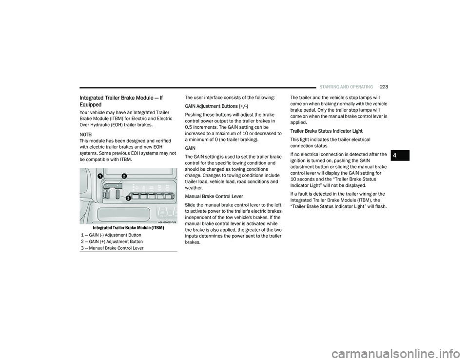
Integrated Trailer Brake Module (ITBM)
The user interface consists of the following:
GAIN Adjustment Buttons (+/-)
Pushing these buttons will adjust the brake
control power output to the trailer brakes in
0.5 increments. The GAIN setting can be
increased to a maximum of 10 or decreased to
a minimum of 0 (no trailer braking).
GAIN
The GAIN setting is used to set the trailer brake
control for the specific towing condition and
should be changed as towing conditions
change. Changes to towing conditions include
trailer load, vehicle load, road conditions and
weather.
Manual Brake Control Lever
Slide the manual brake control lever to the left
to activate power to the trailer's electric brakes
independent of the tow vehicle's brakes. If the
manual brake control lever is activated while
the brake is also applied, the greater of the two
inputs determines the power sent to the trailer
brakes. The trailer and the vehicle’s stop lamps will
come on when braking normally with the vehicle
brake pedal. Only the trailer stop lamps will
come on when the manual brake control lever is
applied.
Trailer Brake Status Indicator Light
This light indicates the trailer electrical
connection status.
If no electrical connection is detected after the
ignition is turned on, pushing the GAIN
adjustment button or sliding the manual brake
control lever will display the GAIN setting for
10 seconds and the “Trailer Brake Status
Indicator Light” will not be displayed.
If a fault is detected in the trailer wiring or the
Integrated Trailer Brake Module (ITBM), the
“Trailer Brake Status Indicator Light” will flash.
1 — GAIN (-) Adjustment Button
2 — GAIN (+) Adjustment Button
3 — Manual Brake Control Lever
4
21_DT_OM_EN_USC_t.book Page 223
Page 226 of 496
224STARTING AND OPERATING
Adjusting GAIN
NOTE:
This should only be performed in a traffic free
environment at speeds of approximately
20–25 mph (30–40 km/h).
1. Make sure the trailer brakes are in good
working condition, functioning normally
and properly adjusted. See your trailer
dealer if necessary.
2. Hook up the trailer and make the electrical connections according to the trailer
manufacturer's instructions.
3. When a trailer is plugged in with electric or EOH brakes, the trailer connected message
should appear in the instrument cluster
display (if the connection is not recognized by the ITBM, braking functions will not be
available), the GAIN setting will illuminate
and the correct type of trailer must be
selected from the instrument cluster display
options.
4. Push the UP or DOWN button on the steering wheel until “TRAILER TOW”
appears on the screen.
5. Push the RIGHT arrow on the steering wheel to enter “TRAILER TOW”.
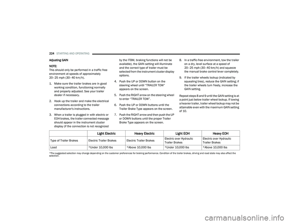
6. Push the UP or DOWN buttons until the Trailer Brake Type appears on the screen.
7. Push the RIGHT arrow and then push the UP or DOWN buttons until the proper Trailer
Brake Type appears on the screen. 8. In a traffic-free environment, tow the trailer
on a dry, level surface at a speed of
20–25 mph (30–40 km/h) and squeeze
the manual brake control lever completely.
9. If the trailer wheels lockup (indicated by squealing tires), reduce the GAIN setting; if
the trailer wheels turn freely, increase the
GAIN setting.
Repeat steps 8 and 9 until the GAIN setting is at
a point just below trailer wheel lockup. If towing
a heavier trailer, trailer wheel lockup may not be
attainable even with the maximum GAIN setting
of 10.
*The suggested selection may change depending on the customer preferences for braking performance. Condition of the trailer brakes, driving and road state may also affect the
selection.
Light Electric Heavy Electric Light EOHHeavy EOH
Type of Trailer Brakes Electric Trailer Brakes Electric Trailer Brakes Electric over Hydraulic
Trailer BrakesElectric over Hydraulic
Trailer Brakes
Load *Under 10,000 lbs *Above 10,000 lbs *Under 10,000 lbs *Above 10,000 lbs
21_DT_OM_EN_USC_t.book Page 224
Page 227 of 496

STARTING AND OPERATING225
Display Messages
The trailer brake control interacts with the
instrument cluster display. Display messages,
along with a single chime, will be displayed
when a malfunction is determined in the trailer
connection, trailer brake control, or on the
trailer Úpage 114. NOTE:
An aftermarket controller may be available
for use with trailers with air or elec
-
tric-over-hydraulic trailer brake systems. To
determine the type of brakes on your trailer
and the availability of controllers, check with
your trailer manufacturer or dealer.
Removal of the ITBM will cause errors and it
may cause damage to the electrical system
and electronic modules of the vehicle. See
your authorized dealer if an aftermarket
module is to be installed.
Towing Requirements — Trailer Lights And
Wiring
Whenever you pull a trailer, regardless of the
trailer size, stoplights and turn signals on the
trailer are required for motoring safety.
The Trailer Tow Package may include a four-pin
and seven-pin wiring harness. Use a factory
approved trailer harness and connector.
NOTE:
Do not cut or splice wiring into the vehicle’s
wiring harness. The electrical connections are all complete to
the vehicle but you must connect the harness to
a trailer connector. Refer to the following
illustrations.
NOTE:
Disconnect trailer wiring connector from the
vehicle before launching a boat (or any other
device plugged into vehicle’s electrical
connect) into water.
Be sure to reconnect once clear from water
area.
Four-Pin Connector
WARNING!
Connecting a trailer that is not compatible
with the ITBM system may result in reduced
or complete loss of trailer braking. There may
be a increase in stopping distance or trailer
instability which could result in personal
injury.
CAUTION!
Connecting a trailer that is not compatible
with the ITBM system may result in reduced
or complete loss of trailer braking. There may
be a increase in stopping distance or trailer
instability which could result in damage to
your vehicle, trailer, or other property.
1 — Ground
2 — Park
3 — Left Stop/Turn
4 — Right Stop/Turn
4
21_DT_OM_EN_USC_t.book Page 225