Lug Nut RAM 1500 2021 Owners Manual
[x] Cancel search | Manufacturer: RAM, Model Year: 2021, Model line: 1500, Model: RAM 1500 2021Pages: 496, PDF Size: 20.89 MB
Page 148 of 496
146STARTING AND OPERATING
(Continued)
COLD WEATHER OPERATION (BELOW
–22°F O
R −30°C)
To ensure reliable starting at these
temperatures, use of an externally powered
electric engine block heater (available from an
authorized dealer) is recommended.
AFTER STARTING
The idle speed is controlled automatically, and
it will decrease as the engine warms up.
STARTING FLUIDS — DIESEL ENGINE
O
NLY
The engine is equipped with a glow plug
preheating system. If the instructions in this
manual are followed, the engine should start in
all conditions and no type of starting fluid
should be used.
NORMAL OPERATION — DIESEL ENGINE
Observe the following when the diesel engine is
operating.
All message center lights are off.
Malfunction Indicator Light (MIL) is off.
Engine Oil Pressure telltale is not illuminated.
Voltmeter operation:
The voltmeter may show a gauge fluctuation at
various engine temperatures. This is caused by
the glow plug heating system. The number of
cycles and the length of the cycling operation is
controlled by the engine control module. Glow
plug heater operation can run for several
minutes, once the heater operation is complete
the voltmeter needle will stabilize.
COLD WEATHER PRECAUTIONS
Operation in ambient temperature below 32°F
(0°C) may require special considerations. The
following charts suggest these options:
WARNING!
Do not leave children or animals inside
parked vehicles in hot weather. Interior
heat build up may cause serious injury or
death.
When leaving the vehicle, always make
sure the wireless ignition node is in the
“OFF” mode, remove the key fob from the
vehicle and lock the vehicle.
Never leave children alone in a vehicle, or
with access to an unlocked vehicle.
Allowing children to be in a vehicle unat -
tended is dangerous for a number of
reasons. A child or others could be seriously
or fatally injured. Children should be
warned not to touch the parking brake,
brake pedal or the gear selector.
Do not leave the key fob in or near the
vehicle, or in a location accessible to chil-
dren, and do not leave the ignition of a
vehicle equipped with Keyless Enter-N-Go
in the ACC or ON/RUN mode. A child could
operate power windows, other controls, or
move the vehicle.
WARNING! (Continued)
21_DT_OM_EN_USC_t.book Page 146
Page 373 of 496

SAFETY371
PERIODIC SAFETY CHECKS YOU SHOULD
M
AKE OUTSIDE THE VEHICLE
Tires
Examine tires for excessive tread wear and
uneven wear patterns. Check for stones, nails,
glass, or other objects lodged in the tread or
sidewall. Inspect the tread for cuts and cracks.
Inspect sidewalls for cuts, cracks, and bulges.
Check the lug nut/bolt torque for tightness.
Check the tires (including spare) for proper cold
inflation pressure.
Lights
Have someone observe the operation of brake
lights and exterior lights while you work the
controls. Check turn signal and high beam
indicator lights on the instrument panel.
Door Latches
Check for proper closing, latching, and locking.
Fluid Leaks
Check area under the vehicle after overnight
parking for fuel, coolant, oil, or other fluid leaks.
Also, if gasoline fumes are detected or if fuel or
brake fluid leaks are suspected, the cause
should be located and corrected immediately.
EXHAUST GAS The best protection against carbon monoxide
entry into the vehicle body is a properly
maintained engine exhaust system.
Whenever a change is noticed in the sound of
the exhaust system, when exhaust fumes can
be detected inside the vehicle, or when the
underside or rear of the vehicle is damaged,
have an authorized dealer inspect the complete
exhaust system and adjacent body areas for
broken, damaged, deteriorated, or
mispositioned parts. Open seams or loose
connections could permit exhaust fumes to
seep into the passenger compartment. In
addition, inspect the exhaust system each time
the vehicle is raised for lubrication or oil
change. Replace as required.
WARNING!
Exhaust gases can injure or kill. They contain
carbon monoxide (CO), which is colorless and
odorless. Breathing it can make you
unconscious and can eventually poison you.
To avoid breathing (CO), follow these safety
tips:
Do not run the engine in a closed garage or
in confined areas any longer than needed
to move your vehicle in or out of the area.
If you are required to drive with the trunk/
liftgate/rear doors open, make sure that all
windows are closed and the climate control
BLOWER switch is set at high speed. DO
NOT use the recirculation mode.
If it is necessary to sit in a parked vehicle
with the engine running, adjust your
heating or cooling controls to force outside
air into the vehicle. Set the blower at high
speed.
6
21_DT_OM_EN_USC_t.book Page 371
Page 381 of 496
IN CASE OF EMERGENCY379
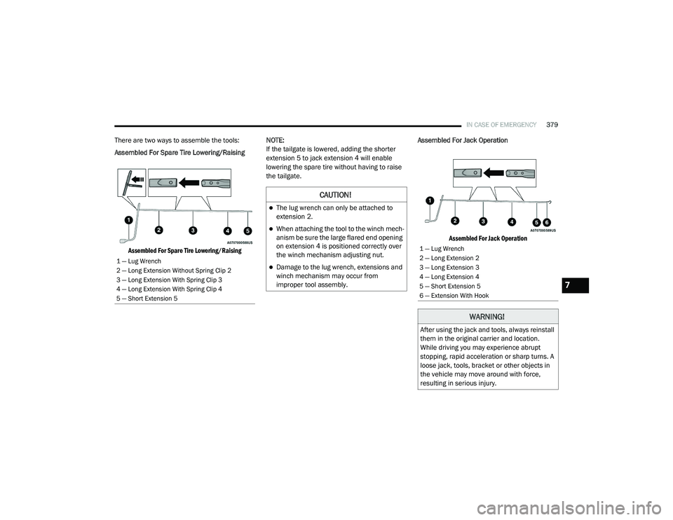
There are two ways to assemble the tools:
Assembled For Spare Tire Lowering/Raising
Assembled For Spare Tire Lowering/Raising
NOTE:
If the tailgate is lowered, adding the shorter
extension 5 to jack extension 4 will enable
lowering the spare tire without having to raise
the tailgate.
Assembled For Jack Operation
Assembled For Jack Operation
1 — Lug Wrench
2 — Long Extension Without Spring Clip 2
3 — Long Extension With Spring Clip 3
4 — Long Extension With Spring Clip 4
5 — Short Extension 5
CAUTION!
The lug wrench can only be attached to
extension 2.
When attaching the tool to the winch mech -
anism be sure the large flared end opening
on extension 4 is positioned correctly over
the winch mechanism adjusting nut.
Damage to the lug wrench, extensions and
winch mechanism may occur from
improper tool assembly.
1 — Lug Wrench
2 — Long Extension 2
3 — Long Extension 3
4 — Long Extension 4
5 — Short Extension 5
6 — Extension With Hook
WARNING!
After using the jack and tools, always reinstall
them in the original carrier and location.
While driving you may experience abrupt
stopping, rapid acceleration or sharp turns. A
loose jack, tools, bracket or other objects in
the vehicle may move around with force,
resulting in serious injury.
7
21_DT_OM_EN_USC_t.book Page 379
Page 384 of 496

382IN CASE OF EMERGENCY
1. Remove the spare tire, jack, and tools from
the stored location.
2. Using the lug wrench, loosen the wheel nuts (but do not remove), by turning them
counterclockwise one turn while the wheel
is still on the ground.
3. Assemble the jack and jacking tools. Connect the jack handle driver to the
extension, then to the lug wrench.
Assembled Jack And Tools
4. Placement for the front and rear jacking
locations are critical. See below images for
proper jacking locations.
Jack / Extensions Placement
Front Jacking Location
When changing a front wheel, place the
scissor jack under the rear portion of the
lower control arm as shown. Access the
front jacking location from behind the front
tire.
Front Lifting Point
Front Jacking Location
Rear Jacking Location
Operate the jack using the extension with
jack hook and the lug wrench. The exten -
sion tubes may be used but is not required.
CAUTION!
Do not attempt to raise the vehicle by jacking
on locations other than those indicated in the
Jacking Instructions for this vehicle.
21_DT_OM_EN_USC_t.book Page 382
Page 385 of 496

IN CASE OF EMERGENCY383
When changing a rear wheel, assemble the
extension with jack hook to the jack and
connect the extension tubes. Access the
rear jacking location from behind the rear
tire. Place the jack under the Jack Lifting
Point located on the rear axle lower control
arm bracket. Then locate the slot in the jack
lift plate onto the rear axle Jack Lifting Point.
Attach the extension with jack hook extend -
ing to the rear of the vehicle.
Rear Lifting Point Rear Jacking Location
Connect the long extensions to the lug
wrench.
5. By rotating the lug wrench clockwise, raise the vehicle until the wheel just clears the
ground surface. 6. Remove the lug nuts and pull the wheel off.
Install the spare wheel and lug nuts with the
cone shaped end of the lug nuts toward the
wheel. Hand tighten the lug nuts with the
vehicle lifted. To avoid the risk of forcing the
vehicle off the jack, do not fully tighten the
lug nuts until the vehicle has been
completely lowered.
7. Finish tightening the lug nuts. Push down on the wrench handle for increased leverage.
Tighten the lug nuts in a star pattern until
each lug nut has been tightened twice
Úpage 467. If in doubt about the correct
tightness, have them checked with a torque
wrench by an authorized dealer or at a
service station.
CAUTION!
Before raising the wheel off the ground, make
sure that the jack will not damage
surrounding truck parts and adjust the jack
position as required.
WARNING!
Raising the vehicle higher than necessary can
make the vehicle less stable. It could slip off
the jack and hurt someone near it. Raise the
vehicle only enough to remove the tire.
7
21_DT_OM_EN_USC_t.book Page 383
Page 390 of 496
388IN CASE OF EMERGENCY
1. Connect the positive
(+) end of the jumper
cable to the positive (+)
post of the
discharged vehicle.
NOTE:
Do not jump off fuses. Only jump directly off
positive post.
2. Connect the opposite end of the positive (+)
jumper cable to the positive (+) post of the
booster battery.
3. Connect the negative (-) end of the jumper
cable to the negative (-) post of the booster
battery.
4. Connect the opposite end of the negative (-)
jumper cable to a good engine ground. A
“ground” is an exposed metallic/unpainted
part of the engine, frame or chassis, such as
an accessory bracket or large bolt. The
ground must be away from the battery and
the fuel injection system. 5. Start the engine in the vehicle that has the
booster battery, let the engine idle a few
minutes, and then start the engine in the
vehicle with the discharged battery.
6. Once the engine is started, follow the disconnection procedure below.
Disconnecting The Jumper Cables
1. Disconnect the negative
(-)
end of the
jumper cable from the engine ground of
the vehicle with the discharged battery.
2. Disconnect the opposite end of the negative (-) jumper cable from the negative (-) post of
the booster battery. 3. Disconnect the positive
(+) end of the
jumper cable from the positive (+) post of
the booster battery.
4. Disconnect the opposite end of the positive (+) jumper cable from the positive
(+) post of the vehicle with the discharged
battery.
If frequent jump starting is required to start your
vehicle you should have the battery and
charging system inspected at an authorized
dealer.
WARNING!
Do not connect the jumper cable to the
negative (-) post of the discharged battery.
The resulting electrical spark could cause the
battery to explode and could result in
personal injury.
CAUTION!
Do not connect jumper cable to any of the
fuses on the positive battery terminal. The
resulting electrical current will blow the fuse.
CAUTION!
Accessories plugged into the vehicle power
outlets draw power from the vehicle’s battery,
even when not in use (i.e., cellular devices, etc.).
Eventually, if plugged in long enough without
engine operation, the vehicle’s battery will
discharge sufficiently to degrade battery life
and/or prevent the engine from starting.
21_DT_OM_EN_USC_t.book Page 388
Page 469 of 496

467
TECHNICAL SPECIFICATIONS
VEHICLE IDENTIFICATION NUMBER
The Vehicle Identification Number (VIN) is found
on the left front corner of the instrument panel,
visible through the windshield.
Vehicle Identification Number
NOTE:
It is illegal to remove or alter the VIN.
BRAKE SYSTEM
If power assist is lost for any reason (for
example, repeated brake applications with the
engine off), the brakes will still function.
However, you will experience a substantial
increase in braking effort to stop the vehicle.
If either the front or rear hydraulic system loses
normal braking capability, the remaining
system will still function with some loss of
overall braking effectiveness. This will be
evident by increased pedal travel during
application, greater pedal force required to slow
or stop, and the “Brake Warning Light” and the
“ABS Warning Light” will activate during brake
use.
WHEEL AND TIRE TORQUE SPECIFICATIONS
Proper lug nut/bolt torque is very important to
ensure that the wheel is properly mounted to
the vehicle. Any time a wheel has been removed
and reinstalled on the vehicle, the lug nuts/
bolts should be torqued using a properly
calibrated torque wrench using a six sided (hex)
deep wall socket.
TORQUE SPECIFICATIONS
**Use only authorized dealer recommended lug nuts/
bolts and clean or remove any dirt or oil before tightening.
Lug Nut/ Bolt
Torque Lug Nut/
Bolt Type **Lug
Nut/Bolt Size Lug Nut/
Bolt
Socket Size
130
Ft-Lbs
(176 N·m) Cone
M14 x
1.50 22 mm
9
21_DT_OM_EN_USC_t.book Page 467
Page 470 of 496

468TECHNICAL SPECIFICATIONS
NOTE:
Do not oil wheel studs. For chrome wheels, do
not substitute with chrome plated wheel nuts.
Inspect the wheel mounting surface prior to
mounting the tire and remove any corrosion or
loose particles.
Wheel Mounting Surface
Tighten the lug nuts/bolts in a star pattern until
each nut/bolt has been tightened twice. Ensure
that the socket is fully engaged on the lug nut/
bolt (do not insert it halfway).
After 25 miles (40 km), check the lug nut/bolt torque to be sure that all the lug nuts/bolts are
properly seated against the wheel.
Four, Five, And Six Lug Nuts/Bolts Torque Pattern
FUEL REQUIREMENTS — GASOLINE ENGINE
While operating on gasoline with the required
octane number, hearing a light knocking sound
from the engine is not a cause for concern.
However, if the engine is heard making a heavy
knocking sound, see a dealer immediately. Use
of gasoline with a lower than recommended octane number can cause engine failure and
may void or not be covered by the New Vehicle
Limited Warranty.
Poor quality gasoline can cause problems such
as hard starting, stalling, and hesitations. If you
experience these symptoms, try another brand
of gasoline before considering service for the
vehicle.
3.6L ENGINE
Do not use E-85 flex fuel or ethanol blends
greater than 15% in this engine.
This engine is designed to meet all
emissions regulations and provide
optimum fuel economy and
performance when using high quality
unleaded “Regular” gasoline having a posted
octane number of 87 as specified by the (R+M)/
2 method. The use of higher octane “Premium”
gasoline is not required, as it will not provide
any benefit over “Regular” gasoline in these
engines.WARNING!
To avoid the risk of forcing the vehicle off the
jack, do not tighten the lug nuts/bolts fully
until the vehicle has been lowered. Failure to
follow this warning may result in personal
injury.
21_DT_OM_EN_USC_t.book Page 468
Page 489 of 496

487
J
Jack Location
................................................. 377Jump Starting................................................ 386
K
Key Fob Programming Additional Key Fobs
.............. 20Key Fob Battery Service (Remote Keyless
Entry)............................................................... 18Key Fob Programming (Remote Keyless
Entry)............................................................... 20Keyless Enter-N-Go................................. 28, 143Passive Entry............................................... 28Keys................................................................. 17
L
Lane Change And Turn Signals........................ 55Lane Change Assist......................................... 55LaneSense.................................................... 199Lap/Shoulder Belts....................................... 336Latches.......................................................... 371Hood........................................................... 84Lead Free Gasoline........................................ 468Leaks, Fluid................................................... 371Life Of Tires................................................... 452Light Bulbs........................................... 371, 437
Lights............................................................ 371Air Bag.................................... 126, 342, 369Brake Assist Warning............................... 314Brake Warning.......................................... 126Bulb Replacement.................................... 437Cargo........................................................... 56Center Mounted Stop............................... 442Courtesy/Reading....................................... 57Cruise....................................................... 136Daytime Running......................................... 53Electronic Stability Program (ESP)Indicator............................................... 128Exterior...............................................52, 371Fog........................................................... 441Hazard Warning Flasher........................... 373Headlights............................................ 52, 54High Beam................................................... 53High Beam/Low Beam Select...................... 53Hill Descent Control Indicator................... 315Illuminated Entry......................................... 58Interior......................................................... 57Lights On Reminder..................................... 55Low Fuel................................................... 131Malfunction Indicator (Check Engine)....... 130Park.......................................................... 135Passing........................................................ 54
Seat Belt Reminder.................................. 126Security Alarm.......................................... 127Service...................................................... 437Traction Control........................................ 314Turn Signals............55, 136, 371, 439, 441Warning Instrument ClusterDescriptions................................ 128, 136Limited-Slip Differential....................... 174, 427Load Shed Battery Saver Mode..................... 125Load Shed Battery Saver On......................... 125Load Shed Electrical Load Reduction........... 125Load Shed Intelligent Battery Sensor............ 125Loading Vehicle............................................. 213Tires.......................................................... 447LocksAutomatic Door............................................30Child Protection...........................................31Power Door..................................................28Low Tire Pressure System............................. 327Lubrication, Body.......................................... 418Lug Nuts........................................................ 467Lug Nuts/Bolts.............................................. 467
M
Maintenance.............................................81, 84Maintenance Free Battery............................ 409Maintenance Schedule............... 395, 399, 40011
21_DT_OM_EN_USC_t.book Page 487