display RAM 1500 2022 Owners Manual
[x] Cancel search | Manufacturer: RAM, Model Year: 2022, Model line: 1500, Model: RAM 1500 2022Pages: 496, PDF Size: 18.03 MB
Page 306 of 496
304MULTIMEDIA
The following describes each feature and its
operation:
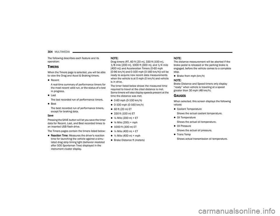
TIMERS
When the Timers page is selected, you will be able
to view the Drag and Accel & Braking timers.
Recent
A real-time summary of performance timers for
the most recent valid run, or the status of a test
in progress.
Last
The last recorded run of performance timers.
Best
The best recorded run of performance timers,
except for braking data.
Save
Pressing the SAVE button will let you save the timer
data for Recent, Last, and Best recorded times to
an inserted USB flash drive.
The Timers pages contain the timers listed below:
Reaction Time: Measures the driver's reaction
time for launching the vehicle against a simu -
lated drag strip timing light (behavior modeled
after 500 Sportsman Tree) displayed in the
instrument cluster display.
NOTE:Drag timers (RT, 60 ft [20 m], 330 ft [100 m],
1/8 mile [200 m], 1000 ft [300 m], and 1/4 mile
[400 m]) and Acceleration Timers (0-60 mph
[0-96 km/h] and 0-100 mph [0-160 km/h]) will be
ready to acquire new recent data measurements
when the vehicle is at 0 mph (0 km/h) and vehicle
is in drive.
The timer listed below shows the measured time
required to travel at the cited distance is met.
Some timers will also display speeds present at the
time the distance was met.
0-60 mph (0-100 km/h)
0-100 mph (0-160 km/h)
60 ft (20 m) ET
330 ft (100 m) ET
⅛ Mile (200 m) + ET
⅛ Mile (200) + mph
1000 ft (300 m) ET
¼ Mile (400 m) + ET
¼ Mile (400 m) + mph
Brake Distance ft (meters)
NOTE:The distance measurement will be aborted if the
brake pedal is released or the parking brake is
engaged, before the vehicle comes to a complete
stop.
Brake from mph (km/h)
NOTE:Brake Distance and Speed timers only display
“ready” when vehicle is traveling at a speed
greater than 30 mph (48 km/h).
GAUGES
When selected, this screen displays the following
values:
Coolant Temperature
Shows the actual coolant temperature.
Oil Temperature
Shows the actual oil temperature.
Oil Pressure
Shows the actual oil pressure.
Trans Temp
Shows actual transmission oil temperature.
22_DT_OM_EN_USC_t.book Page 304
Page 307 of 496

MULTIMEDIA305
Battery Voltage
Shows actual battery voltage.
Intake Air Temp
Shows actual intake air temperature.
If a gauge is selected, the Gauge Detail View Page
will appear on the screen. This page shows gauge
values for the previous two minutes on the
selected gauge.
Pressing the Left or Right Arrow will cycle through
the details for each of the gauges. Pressing the
minimize button beside the graph will return to the
Gauge menu.
G-FORCE
When G-Force is selected, the following features
will be available:
Vehicle Speed
Measures the current speed of the vehicle in
either mph or km/h, starting at zero with no
maximum value.
Front G-Force
Measures the peak braking force on the front of
the vehicle.
Right G-Force
Measures the peak force on the right side of the
vehicle.
Left G-Force
Measures the peak force on the left side of the
vehicle.
Rear G-Force
Measures the peak acceleration force on the
rear of the vehicle.
NOTE:Front, Right, Left, and Rear G-Forces are all peak
values. These readings can be reset by clearing
peak G-Force on the instrument cluster.
The friction circle display shows instantaneous
G-Force as a highlight and previous G-Force as
dots within the circle. The system records previous
G-Force for three minutes. If there are multiple
samples at a given point, the color of the dot will
darken from blue to red. Vectors more frequent will
show in red; infrequent vectors will show in blue.
Pitch & Roll
The G-Force page displays the vehicle’s current
pitch (angle up and down) and roll (angle side to
side) in degrees. The pitch and roll gauges provide
a visualization of the current vehicle angle.
DYNAMOMETER (DYNO)/ENGINE
Dynamometer (Dyno)
The system will start drawing graphs for Power and
Torque (top chart) and Engine Speed (bottom
chart). The graph will fill from the left side of the
x-axis and fill to the right side of the x-axis (based
on History time selected). Once the right side of the
page is reached, the graph will scroll with the right
side always being the most recent recorded
sample.
The following options can be selected:
Pressing the STOP button will freeze the graph.
Selecting “Play” will clear the graph and restart
the process.
Press the + or – button to change the history of
the graph. The selectable options are “30”,
“60”, “90”, “120” seconds. The graph will
expand or constrict depending on the setting
selected.
Select the “Gear” display setting to turn the
graph gear markers on or off.
NOTE:The Gear On/Off feature will only display if your
vehicle is equipped with an Automatic Trans -
mission.
5
22_DT_OM_EN_USC_t.book Page 305
Page 308 of 496

306MULTIMEDIA
Engine
Press the Left and Right Arrow buttons on the
bottom of the touchscreen to cycle between the
Dyno and Engine pages.
When selected, this screen displays the following
values:
Vehicle Speed: Shows the actual vehicle speed.
Engine Power: Shows the instantaneous power.
Engine Torque : Shows the instantaneous
torque.
Boost Pressure : Shows the actual engine boost
pressure.
Gear : Shows the current (or pending) operating
gear of the vehicle.
VEHICLE DYNAMICS
The Vehicle Dynamics page displays information
concerning the vehicle’s drivetrain.
Steering Angle — If Equipped
Steering Angle utilizes the steering angle sensor to
calculate the degree of the steering relative to zero
(straight ahead) reference angle. The zero degree
reference angle measurement indicates the actual
front tire steering angle. Transfer Case
This feature will be active when the vehicle is in
4WD HIGH, 4WD AUTO, Neutral, or 4WD LOW.
NOTE:A lock symbol will only be present on the Transfer
Case button when the vehicle is in 4WD LOW.
Rear Axle Locker
This feature will allow you to lock and unlock the
rear axle. To change the status, push the AXLE
LOCK button.
OFF-ROAD PAGES — IF EQUIPPED
Your vehicle may be equipped with Off-Road Pages
which display vehicle information related to the
drivetrain, transfer case, and coolant/oil gauges.
To access Off-Road Pages, press the Vehicle
button on the touchscreen, select the Off-Road
Pages tab, and then select the Off-Road button on
the main screen. Off-Road Pages can also be
accessed through the app drawer.
Off-Road Button
22_DT_OM_EN_USC_t.book Page 306
Page 310 of 496
308MULTIMEDIA
VEHICLE DYNAMICS
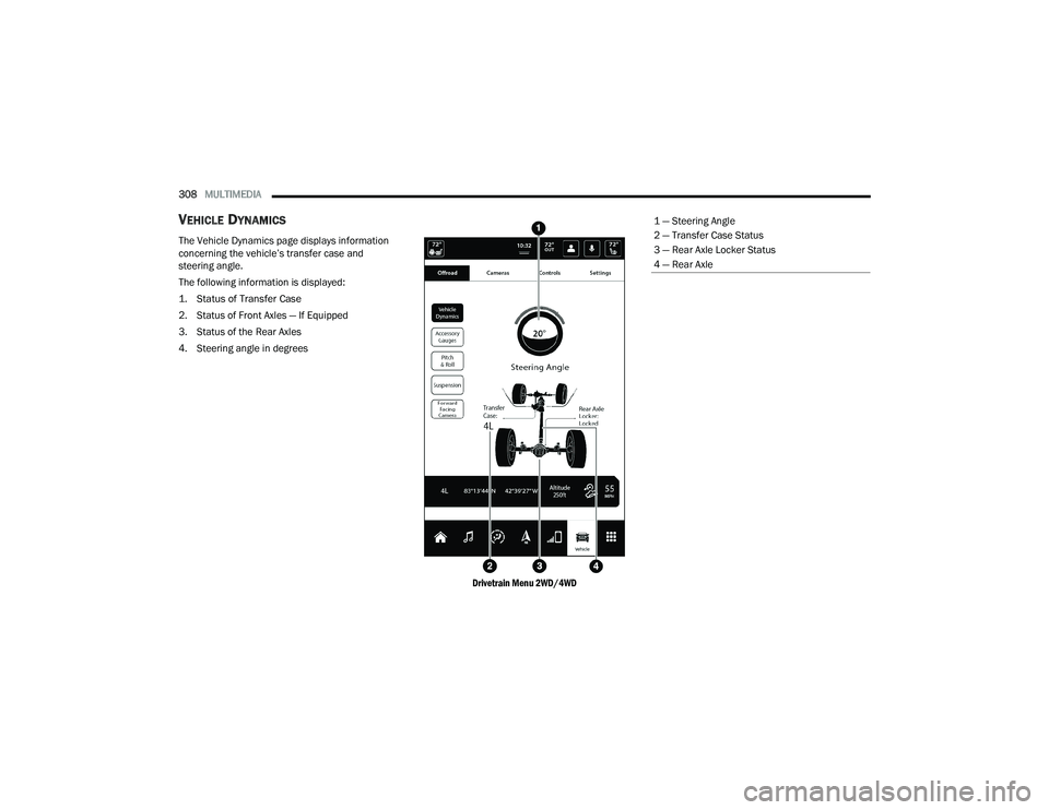
The Vehicle Dynamics page displays information
concerning the vehicle’s transfer case and
steering angle.
The following information is displayed:
1. Status of Transfer Case
2. Status of Front Axles — If Equipped
3. Status of the Rear Axles
4. Steering angle in degrees
Drivetrain Menu 2WD/4WD
1 — Steering Angle
2 — Transfer Case Status
3 — Rear Axle Locker Status
4 — Rear Axle
22_DT_OM_EN_USC_t.book Page 308
Page 311 of 496
MULTIMEDIA309
ACCESSORY GAUGE
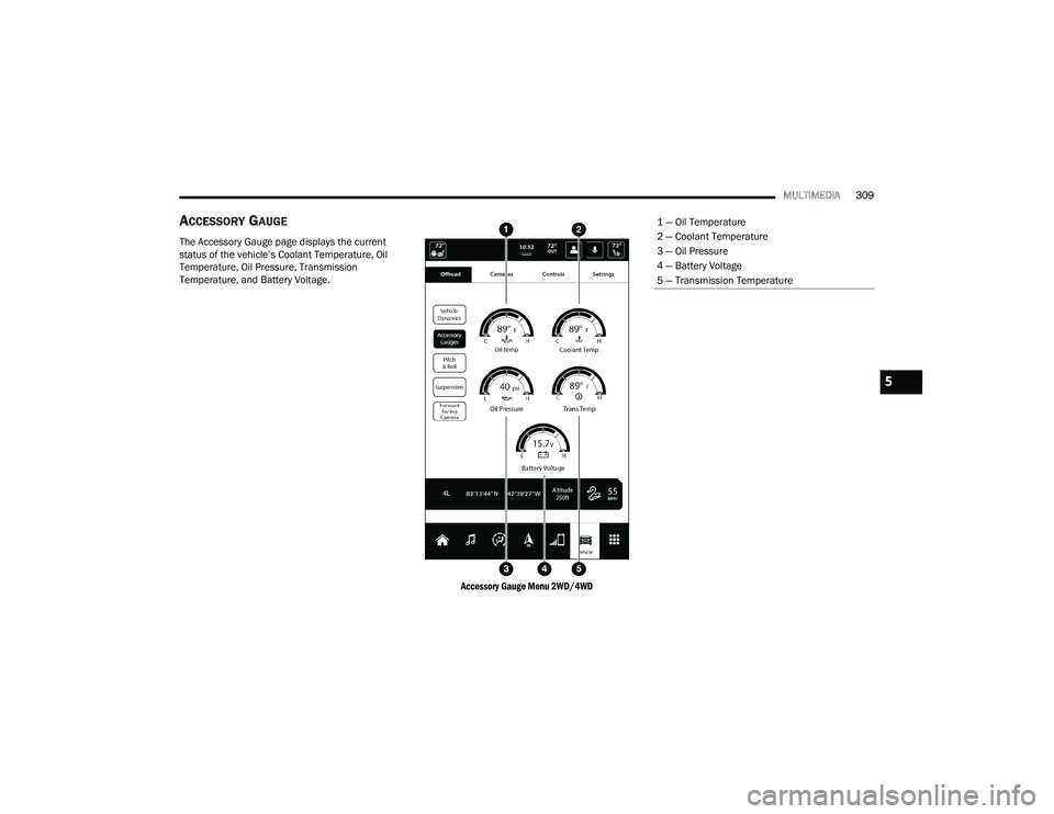
The Accessory Gauge page displays the current
status of the vehicle’s Coolant Temperature, Oil
Temperature, Oil Pressure, Transmission
Temperature, and Battery Voltage.
Accessory Gauge Menu 2WD/4WD
1 — Oil Temperature
2 — Coolant Temperature
3 — Oil Pressure
4 — Battery Voltage
5 — Transmission Temperature
5
22_DT_OM_EN_USC_t.book Page 309
Page 312 of 496
310MULTIMEDIA
PITCH & ROLL
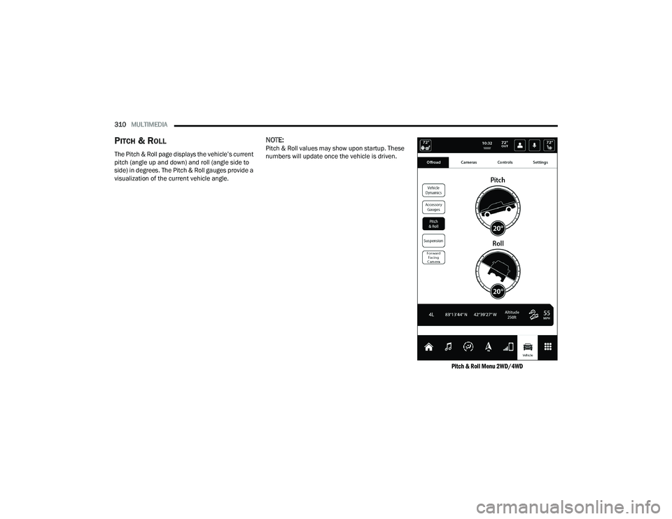
The Pitch & Roll page displays the vehicle’s current
pitch (angle up and down) and roll (angle side to
side) in degrees. The Pitch & Roll gauges provide a
visualization of the current vehicle angle.
NOTE:Pitch & Roll values may show upon startup. These
numbers will update once the vehicle is driven.
Pitch & Roll Menu 2WD/4WD
22_DT_OM_EN_USC_t.book Page 310
Page 313 of 496
MULTIMEDIA311
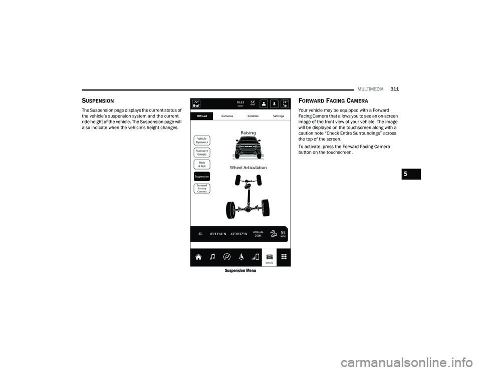
SUSPENSION
The Suspension page displays the current status of
the vehicle’s suspension system and the current
ride height of the vehicle. The Suspension page will
also indicate when the vehicle’s height changes.
Suspension Menu
FORWARD FACING CAMERA
Your vehicle may be equipped with a Forward
Facing Camera that allows you to see an on-screen
image of the front view of your vehicle. The image
will be displayed on the touchscreen along with a
caution note “Check Entire Surroundings” across
the top of the screen.
To activate, press the Forward Facing Camera
button on the touchscreen.
5
22_DT_OM_EN_USC_t.book Page 311
Page 317 of 496

SAFETY315
ESC Operating Modes
Depending upon model and mode of operation, the
ESC system may have multiple operating modes.
ESC On
This is the normal operating mode for the ESC.
Whenever the vehicle is started, the ESC system
will be in this mode. This mode should be used for
most driving conditions. Alternate ESC modes
should only be used for specific reasons as noted
in the following paragraphs. Partial Off
This mode may be useful if the vehicle becomes
stuck. This mode may modify TCS and ESC
thresholds for activation, which allows for more
wheel spin than normally allowed.
To enter the “Partial Off” mode, momentarily push
the ESC OFF button and the ESC OFF Indicator
Light will illuminate. To turn the ESC on again,
momentarily push the ESC OFF button and the ESC
OFF Indicator Light will turn off.
NOTE:For vehicles with multiple partial ESC modes, the
push and release of the button will toggle the ESC
modes. Multiple attempts may be required to
return to “ESC On”.
Full Off — If Equipped
This mode is intended for off-highway or off-road
use only and should not be used on any public
roadways. In this mode, TCS and ESC features are
turned off. To enter the “Full Off” mode, push and
hold the ESC OFF button for five seconds while the
vehicle is stopped with the engine running. After
five seconds, a chime will sound, the ESC OFF
Indicator Light will illuminate, and the “ESC OFF”
message will display in the instrument cluster. To
turn ESC on again, momentarily push the ESC OFF
button.NOTE:System may switch from ESC “Full Off” to “Partial
Off” mode when vehicle exceeds a predetermined
speed. When the vehicle speed slows below the
predetermined speed the system will return to ESC
“Full Off”.
ESC modes may also be affected by drive modes (if
equipped).
Vehicle modifications, or failure to properly
maintain your vehicle, may change the
handling characteristics of your vehicle, and
may negatively affect the performance of the
ESC system. Changes to the steering system,
suspension, braking system, tire type and size
or wheel size may adversely affect ESC perfor
-
mance. Improperly inflated and unevenly worn
tires may also degrade ESC performance. Any
vehicle modification or poor vehicle mainte -
nance that reduces the effectiveness of the
ESC system can increase the risk of loss of
vehicle control, vehicle rollover, personal
injury and death.
WARNING!
WARNING!
When in “Partial Off” mode, the TCS function -
ality of ESC (except for the limited slip feature
described in the TCS section) has been
disabled and the ESC OFF Indicator Light will
be illuminated. When in “Partial Off” mode,
the engine power reduction feature of TCS is
disabled, and the enhanced vehicle stability
offered by the ESC system is reduced.
Trailer Sway Control (TSC) is disabled when
the ESC system is in the “Partial Off” mode.
6
22_DT_OM_EN_USC_t.book Page 315
Page 322 of 496
320SAFETY
The BSM detection zone covers approximately one
lane width on both sides of the vehicle 12 ft
(3.8 m). The zone length starts at the outside
rearview mirror and extends approximately 10 ft
(3 m) beyond the rear fascia/bumper of the
vehicle. The BSM system monitors the detection
zones on both sides of the vehicle when the vehicle
speed reaches approximately 6 mph (10 km/h) or
higher and will alert the driver of vehicles in these
areas.
NOTE:
The BSM system DOES NOT alert the driver
about rapidly approaching vehicles that are
outside the detection zones.
BSM may experience dropouts (blinking on and
off) of the side mirror warning indicator lamps
when a motorcycle or any small object remains
at the side of the vehicle for extended periods of
time (more than a couple of seconds).
The BSM system can become blocked if snow, ice,
mud, or other road contaminations accumulate on
the rear fascia/bumper where the radar sensors
are located. The system may also detect blockage
if the vehicle is operated in areas with extremely
low radar returns such as a desert or parallel to a
large elevation drop. If blockage is detected, a
“Blind Spot Temporarily Unavailable, Wipe Rear
Corners” message will display in the cluster, both
mirror lights will illuminate, and BSM and RCP
alerts will not occur. This is normal operation. The system will automatically recover and resume
function when the condition clears. To minimize
system blockage, do not block the area of the rear
fascia/bumper where the radar sensors are
located with foreign objects (bumper stickers,
bicycle racks, etc.) and keep it clear of road
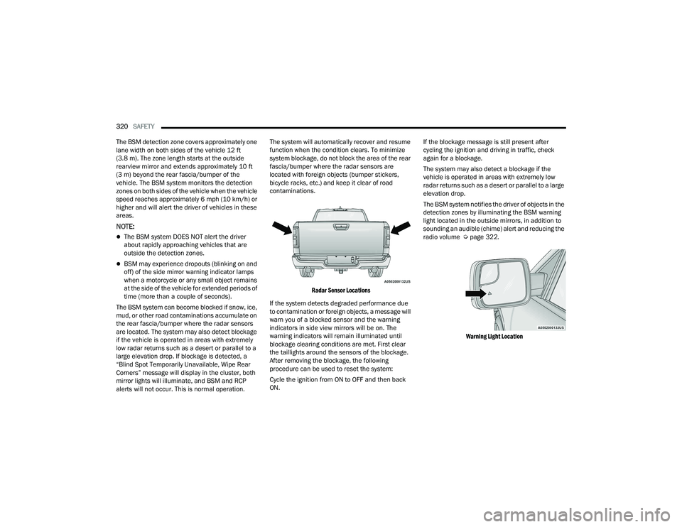
contaminations.
Radar Sensor Locations
If the system detects degraded performance due
to contamination or foreign objects, a message will
warn you of a blocked sensor and the warning
indicators in side view mirrors will be on. The
warning indicators will remain illuminated until
blockage clearing conditions are met. First clear
the taillights around the sensors of the blockage.
After removing the blockage, the following
procedure can be used to reset the system:
Cycle the ignition from ON to OFF and then back
ON. If the blockage message is still present after
cycling the ignition and driving in traffic, check
again for a blockage.
The system may also detect a blockage if the
vehicle is operated in areas with extremely low
radar returns such as a desert or parallel to a large
elevation drop.
The BSM system notifies the driver of objects in the
detection zones by illuminating the BSM warning
light located in the outside mirrors, in addition to
sounding an audible (chime) alert and reducing the
radio volume Ú
page 322.
Warning Light Location
22_DT_OM_EN_USC_t.book Page 320
Page 326 of 496
324SAFETY
Automatic Trailer Detection
There are two modes of operation for the detection
of the trailer length:
Automatic Mode — When “Auto Mode” is
selected, the system will use the blind spot
sensors to automatically determine the pres -
ence and length of a trailer. The presence of a
trailer will be detected using the blind spot radar
within 90 seconds of forward movement of the
vehicle. The vehicle must be moving above
6 mph (10 km/h) to activate the feature. Once
the trailer has been detected, the system will
default to the maximum blind spot zone until the
length has been verified. You will see “Auto” in
the instrument panel cluster .
Maximum Mode — When “Max Mode” is
selected, the system will default to the
maximum blind spot zone regardless of what
size trailer is attached .
NOTE:Selected setting is stored when the ignition is
placed in the OFF position. To change this setting,
it must be selected through the Uconnect Settings
Ú page 234. Trailer Length Detection
Once the trailer presence has been established,
the trailer length will be established (by making a
90 degree turn) and then the trailer length
category (example 10-20 ft (3 m to 6 m)) will be
displayed. This can take up to 30 seconds after
completing the turn.
NOTE:During the same ignition cycle, if the vehicle is at a
standstill for a minimum of 90 seconds, a new
“trailer detection request” is enabled by the
system once the vehicle resumes motion.
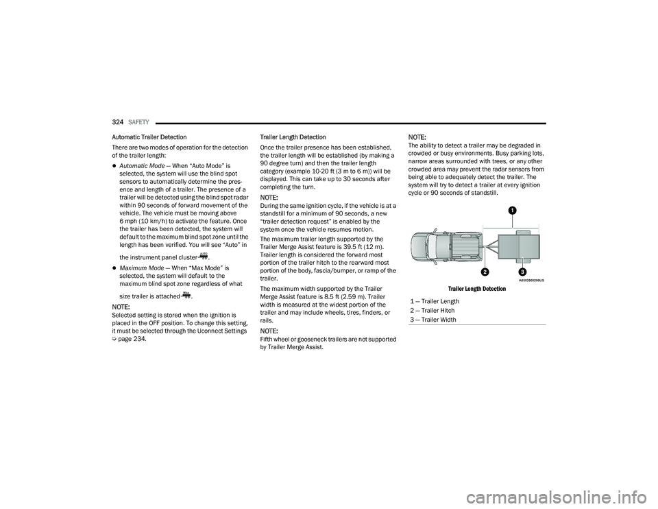
The maximum trailer length supported by the
Trailer Merge Assist feature is 39.5 ft (12 m).
Trailer length is considered the forward most
portion of the trailer hitch to the rearward most
portion of the body, fascia/bumper, or ramp of the
trailer.
The maximum width supported by the Trailer
Merge Assist feature is 8.5 ft (2.59 m). Trailer
width is measured at the widest portion of the
trailer and may include wheels, tires, finders, or
rails.
NOTE:Fifth wheel or gooseneck trailers are not supported
by Trailer Merge Assist.
NOTE:The ability to detect a trailer may be degraded in
crowded or busy environments. Busy parking lots,
narrow areas surrounded with trees, or any other
crowded area may prevent the radar sensors from
being able to adequately detect the trailer. The
system will try to detect a trailer at every ignition
cycle or 90 seconds of standstill.
Trailer Length Detection
1 — Trailer Length
2 — Trailer Hitch
3 — Trailer Width
22_DT_OM_EN_USC_t.book Page 324