jack and tools RAM 1500 2022 Owners Manual
[x] Cancel search | Manufacturer: RAM, Model Year: 2022, Model line: 1500, Model: RAM 1500 2022Pages: 496, PDF Size: 18.03 MB
Page 9 of 496
7
CONNECTED SERVICES FAQS ........................... 297 Connected Services SOS FAQs —
If Equipped .................................................... 298
Connected Services Remote Door
Lock/Unlock FAQs ........................................ 298
Connected Services Roadside
Assistance FAQs ........................................... 298Connected Services Send & Go FAQs —
If Equipped .................................................... 298
Connected Services Vehicle Finder FAQs ... 299
Connected Services Stolen Vehicle
Assistance FAQs — If Equipped ................... 299
Connected Services Remote Vehicle
Start FAQs ..................................................... 299
Connected Services Remote
Horn & Lights FAQs ....................................... 300
Connected Services Account
FAQs — If Equipped ....................................... 300
Data Collection & Privacy.............................. 302
RADIO OPERATION AND MOBILE PHONES...... 302
Regulatory And Safety Information .............. 303
PERFORMANCE PAGES — IF EQUIPPED...........303
Timers ............................................................ 304
Gauges ........................................................... 304G-Force ........................................................... 305Dynamometer (Dyno)/Engine ....................... 305
Vehicle Dynamics .......................................... 306 OFF-ROAD PAGES — IF EQUIPPED ................... 306
Off-Road Pages Status Bar .......................... 307
Vehicle Dynamics ......................................... 308
Accessory Gauge ........................................... 309Pitch & Roll .................................................... 310
Suspension .................................................... 311
Forward Facing Camera................................ 311
SAFETY
SAFETY FEATURES .............................................. 312
Anti-Lock Brake System (ABS) ..................... 312
Electronic Brake Control (EBC) System ....... 313
AUXILIARY DRIVING SYSTEMS.......................... 319
Blind Spot Monitoring (BSM) —
If Equipped .................................................... 319
Forward Collision Warning (FCW)
With Mitigation — If Equipped ...................... 325Tire Pressure Monitoring System (TPMS) .... 328
OCCUPANT RESTRAINT SYSTEMS ................... 334
Occupant Restraint Systems Features ....... 334
Important Safety Precautions ...................... 334Seat Belt Systems ........................................ 335Supplemental Restraint Systems (SRS) ...... 341Child Restraints ............................................ 354
SAFETY TIPS ........................................................ 368
Transporting Passengers .............................. 368Transporting Pets ....................................... 368 Safety Checks You Should Make
Inside The Vehicle ........................................ 368
Periodic Safety Checks You Should
Make Outside The Vehicle ............................ 369
Exhaust Gas................................................... 370
Carbon Monoxide Warnings ........................ 370
IN CASE OF EMERGENCY
HAZARD WARNING FLASHERS ......................... 371
ASSIST AND SOS SYSTEM — IF EQUIPPED ...... 372
JACKING AND TIRE CHANGING ......................... 375 Preparations For Jacking .............................. 375
Jack Location................................................. 376
Removal Of Jack And Tools .......................... 376
Removing The Spare Tire ............................. 378Jacking Instructions ...................................... 379
To Stow The Flat Or Spare ........................... 382
Reinstalling The Jack And Tools ................... 383
JUMP STARTING .................................................. 384
Preparations For Jump Start ........................ 384Jump Starting Procedure .............................. 385
REFUELING IN EMERGENCY –
IF EQUIPPED ........................................................ 386
IF YOUR ENGINE OVERHEATS ........................... 387
MANUAL PARK RELEASE ................................... 388
FREEING A STUCK VEHICLE .............................. 389
22_DT_OM_EN_USC_t.book Page 7
Page 378 of 496

376IN CASE OF EMERGENCY
6. Block both the front and rear wheel diagonally opposite of each jacking position. For example,
if the driver’s front wheel is being changed,
block the passenger’s rear wheel.
Wheel Blocked
NOTE:Passengers should not remain in the vehicle when
the vehicle is being raised or lifted.
JACK LOCATION
The jack and tools are stored under the front
passenger seat.
REMOVAL OF JACK AND TOOLS
To access the jack and tools, you must remove the
plastic access cover located on the side of the
front passenger’s seat. To remove the cover, pull
the front part of the cover (closest to the front of
the seat) toward you to release a locking tab. Once
the front of the cover is loose, slide the cover
toward the front of the seat until it is free from the
seat frame.
Pull Jack Access Cover From Front
Remove the jack and tools by turning the wing bolt
counterclockwise. After removing the wing bolt,
slide the assembly out from under the seat.
Jack And Tools
Fuel Funnel Location
22_DT_OM_EN_USC_t.book Page 376
Page 379 of 496
IN CASE OF EMERGENCY377
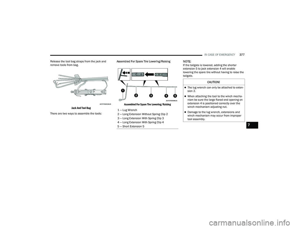
Release the tool bag straps from the jack and
remove tools from bag.
Jack And Tool Bag
There are two ways to assemble the tools: Assembled For Spare Tire Lowering/Raising
Assembled For Spare Tire Lowering/Raising
NOTE:If the tailgate is lowered, adding the shorter
extension 5 to jack extension 4 will enable
lowering the spare tire without having to raise the
tailgate.
1 — Lug Wrench
2 — Long Extension Without Spring Clip 2
3 — Long Extension With Spring Clip 3
4 — Long Extension With Spring Clip 4
5 — Short Extension 5
CAUTION!
The lug wrench can only be attached to exten -
sion 2.
When attaching the tool to the winch mecha -
nism be sure the large flared end opening on
extension 4 is positioned correctly over the
winch mechanism adjusting nut.
Damage to the lug wrench, extensions and
winch mechanism may occur from improper
tool assembly.
7
22_DT_OM_EN_USC_t.book Page 377
Page 380 of 496
378IN CASE OF EMERGENCY
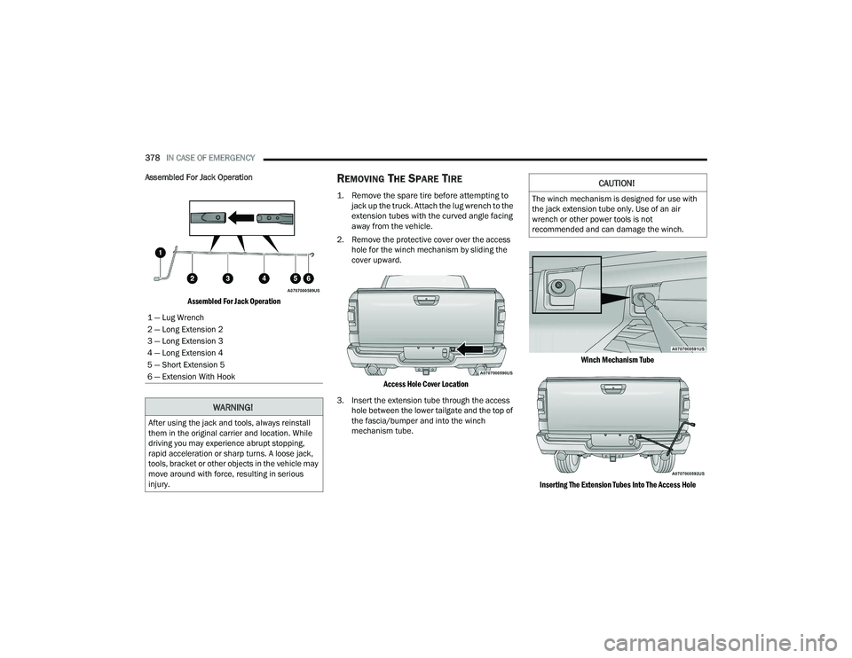
Assembled For Jack Operation
Assembled For Jack Operation
REMOVING THE SPARE TIRE
1. Remove the spare tire before attempting to jack up the truck. Attach the lug wrench to the
extension tubes with the curved angle facing
away from the vehicle.
2. Remove the protective cover over the access hole for the winch mechanism by sliding the
cover upward.
Access Hole Cover Location
3. Insert the extension tube through the access hole between the lower tailgate and the top of
the fascia/bumper and into the winch
mechanism tube.
Winch Mechanism Tube
Inserting The Extension Tubes Into The Access Hole
1 — Lug Wrench
2 — Long Extension 2
3 — Long Extension 3
4 — Long Extension 4
5 — Short Extension 5
6 — Extension With Hook
WARNING!
After using the jack and tools, always reinstall
them in the original carrier and location. While
driving you may experience abrupt stopping,
rapid acceleration or sharp turns. A loose jack,
tools, bracket or other objects in the vehicle may
move around with force, resulting in serious
injury.
CAUTION!
The winch mechanism is designed for use with
the jack extension tube only. Use of an air
wrench or other power tools is not
recommended and can damage the winch.
22_DT_OM_EN_USC_t.book Page 378
Page 382 of 496

380IN CASE OF EMERGENCY
Jack Warning Label
1. Remove the spare tire, jack, and tools from the stored location.
2. Using the lug wrench, loosen the wheel nuts (but do not remove), by turning them counter -
clockwise one turn while the wheel is still on
the ground.
3. Assemble the jack and jacking tools. Connect the jack handle driver to the extension, then to
the lug wrench.
Assembled Jack And Tools
4. Placement for the front and rear jacking locations are critical. See below images for
proper jacking locations.
Jack / Extensions Placement
Front Jacking Location
When changing a front wheel, place the
scissor jack under the rear portion of the
lower control arm as shown. Access the
front jacking location from behind the front
tire.
Front Lifting Point
CAUTION!
Do not attempt to raise the vehicle by jacking on
locations other than those indicated in the
Jacking Instructions for this vehicle.
22_DT_OM_EN_USC_t.book Page 380
Page 384 of 496
382IN CASE OF EMERGENCY
7. Lower the vehicle to the ground and finish tightening the lug nuts. Push down on the
wrench handle for increased leverage. Tighten
the lug nuts in a star pattern until each lug nut
has been tightened twice Ú page 466. If in
doubt about the correct tightness, have them
checked with a torque wrench by an
authorized dealer or at a service station.
8. If your vehicle is equipped with a wheel center cap, install the cap and remove the wheel
blocks. Do not install chrome or aluminum
wheel center caps on the spare wheel. This
may result in cap damage.
9. Lower the jack to its fully closed position. Stow the replaced tire, and secure the jack and tools
in the proper location.
10. Adjust the tire pressure when possible.
TO STOW THE FLAT OR SPARE
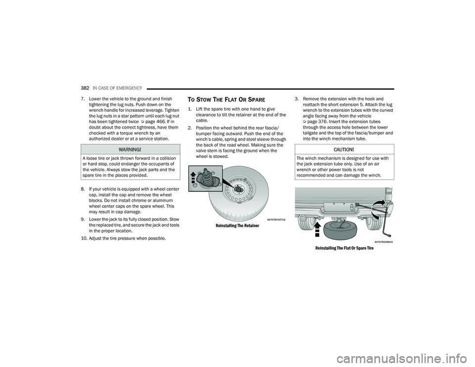
1. Lift the spare tire with one hand to give clearance to tilt the retainer at the end of the
cable.
2. Position the wheel behind the rear fascia/ bumper facing outward. Push the end of the
winch’s cable, spring and steel sleeve through
the back of the road wheel. Making sure the
valve stem is facing the ground when the
wheel is stowed.
Reinstalling The Retainer
3. Remove the extension with the hook and
reattach the short extension 5. Attach the lug
wrench to the extension tubes with the curved
angle facing away from the vehicle
Úpage 376. Insert the extension tubes
through the access hole between the lower
tailgate and the top of the fascia/bumper and
into the winch mechanism tube.
Reinstalling The Flat Or Spare Tire
WARNING!
A loose tire or jack thrown forward in a collision
or hard stop, could endanger the occupants of
the vehicle. Always stow the jack parts and the
spare tire in the places provided.
CAUTION!
The winch mechanism is designed for use with
the jack extension tube only. Use of an air
wrench or other power tools is not
recommended and can damage the winch.
22_DT_OM_EN_USC_t.book Page 382
Page 385 of 496

IN CASE OF EMERGENCY383
4. Rotate the lug wrench handle clockwise until the wheel is drawn into place against the
underside of the vehicle. Continue to rotate
until you feel the winch mechanism slip, or
click three or four times. It cannot be
overtightened. Push against the tire several
times to ensure it is firmly in place.
Rotating The Lug Wrench Handle
NOTE:Have the flat tire repaired or replaced immediately.
REINSTALLING THE JACK AND TOOLS
1. Tighten the jack all the way down by turning the jack turn-screw counterclockwise until the
jack is snug.
2. Position the jack and tool bag. Make sure the lug wrench is under the jack near the jack
turn-screw.
Jack And Tool Bag
3. Secure the tool bag straps to the jack.
Jack And Tools Tied
WARNING!
A loose tire or jack thrown forward in a collision
or hard stop could endanger the occupants of
the vehicle. Always stow the jack parts and the
spare tire in the places provided. Have the
deflated (flat) tire repaired or replaced
immediately.
7
22_DT_OM_EN_USC_t.book Page 383
Page 386 of 496

384IN CASE OF EMERGENCY
4. Place the jack and tools in the storage position holding the jack by the jack turn-screw, slip the
jack and tools under the seat so that the
bottom slot engages into the fastener on the
floor.
NOTE:Ensure that the jack slides into the front hold down
location.
5. Turn the wing bolt clockwise to secure to the floor pan. Reinstall the plastic cover.
Jack Hold Down Wing Bolt
JUMP STARTING
If your vehicle has a discharged battery, it can be
jump started using a set of jumper cables and a
battery in another vehicle, or by using a portable
battery booster pack. Jump starting can be
dangerous if done improperly, so please follow the
procedures in this section carefully.
NOTE:When using a portable battery booster pack, follow
the manufacturer's operating instructions and
precautions.
PREPARATIONS FOR JUMP START
The battery in your vehicle is located in the front of
the engine compartment, behind the left headlight
assembly.
WARNING!
After using the jack and tools, always reinstall
them in the original carrier and location. While
driving you may experience abrupt stopping,
rapid acceleration or sharp turns. A loose jack,
tools, bracket or other objects in the vehicle may
move around with force, resulting in serious
injury.
WARNING!
Do not attempt jump starting if the battery is
frozen. It could rupture or explode and cause
personal injury.
CAUTION!
Do not use a portable battery booster pack or
any other booster source with a system voltage
greater than 12 Volts or damage to the battery,
starter motor, alternator or electrical system may
occur.
22_DT_OM_EN_USC_t.book Page 384
Page 388 of 496

386IN CASE OF EMERGENCY
3. Connect the negative (-) end of the jumper
cable to the negative (-) post of the booster
battery.
4. Connect the opposite end of the negative (-)
jumper cable to a good engine ground. A
“ground” is an exposed metallic/unpainted
part of the engine, frame or chassis, such as
an accessory bracket or large bolt. The ground
must be away from the battery and the fuel
injection system.
Jump Starting Label
5. Start the engine in the vehicle that has the
booster battery, let the engine idle a few
minutes, and then start the engine in the
vehicle with the discharged battery.
6. Once the engine is started, follow the discon -
nection procedure below.
Disconnecting The Jumper Cables
1. Disconnect the negative
(-)
end of the jumper
cable from the engine ground of the vehicle
with the discharged battery.
2. Disconnect the opposite end of the negative (-)
jumper cable from the negative (-) post of the
booster battery.
3. Disconnect the positive (+) end of the jumper
cable from the positive (+) post of the booster
battery.
4. Disconnect the opposite end of the positive (+)
jumper cable from the positive (+) post of the
vehicle with the discharged battery, and
reinstall the protective cap. If frequent jump starting is required to start your
vehicle you should have the battery and charging
system inspected at an authorized dealer.
REFUELING IN EMERGENCY – IF EQUIPPED
The vehicle is equipped with a refueling funnel for
a Cap-Less Fuel System. The refueling funnel can
be found with the jack and tools Ú
page 376. If
refueling is necessary, while using an approved
gas can, insert the refueling funnel into the filler
neck opening. Take care to open both flappers with
the funnel to avoid spills.
NOTE:In certain cold conditions, ice may prevent the fuel
door from opening. If this occurs, lightly push on
the fuel door to break the ice buildup and
re-release the fuel door using the inside release
button. Do not pry on the door.WARNING!
Do not connect the jumper cable to the negative
(-) post of the discharged battery. The resulting
electrical spark could cause the battery to
explode and could result in personal injury.
CAUTION!
Do not connect jumper cable to any of the fuses
on the positive battery terminal. The resulting
electrical current will blow the fuse.
CAUTION!
Accessories plugged into the vehicle power
outlets draw power from the vehicle’s battery,
even when not in use (i.e., cellular devices, etc.).
Eventually, if plugged in long enough without
engine operation, the vehicle’s battery will
discharge sufficiently to degrade battery life
and/or prevent the engine from starting.
22_DT_OM_EN_USC_t.book Page 386