mirror controls RAM 1500 2022 Owners Manual
[x] Cancel search | Manufacturer: RAM, Model Year: 2022, Model line: 1500, Model: RAM 1500 2022Pages: 496, PDF Size: 18.03 MB
Page 5 of 496
3
Power Folding Outside Mirrors For
Standard And Trailer Tow — If Equipped.........48
Trailer Towing Mirrors — If Equipped...............49
Heated Mirrors — If Equipped..........................49
Tilt Side Mirrors In Reverse — If Equipped......49
UNIVERSAL GARAGE DOOR OPENER
(HOMELINK®) — IF EQUIPPED ............................ 49
Before You Begin Programming
HomeLink®.......................................................50
Erasing All The HomeLink® Channels ............50
Identifying Whether You Have A Rolling
Code Or Non-Rolling Code Device ...................50
Programming HomeLink® To A Garage
Door Opener .....................................................51
Programming HomeLink® To A
Miscellaneous Device ......................................52
Reprogramming A Single HomeLink®
Button ...............................................................52
Canadian/Gate Operator Programming .........52
Security .............................................................53
Troubleshooting Tips ........................................53
EXTERIOR LIGHTS.................................................. 54
Headlight Switch...............................................54
Multifunction Lever .........................................55
Daytime Running Lights (DRLs) ......................55
High/Low Beam Switch ...................................55 Automatic High Beam Headlamp
Control — If Equipped ......................................55
Flash-To-Pass ...................................................55
Automatic Headlights — If Equipped ..............56
Parking Lights And Panel Lights ......................56
Automatic Headlights With Wipers .................56
Headlight Delay ................................................56
Lights-On Reminder .........................................56
Fog Lights — If Equipped .................................57
Turn Signals ......................................................57
Lane Change Assist — If Equipped ..................57
Cargo Lights/Trailer Spotter Lights/
Trailer Hitch Light With Bed Lights —
If Equipped........................................................57
Battery Saver ....................................................59
INTERIOR LIGHTS ..................................................59
Courtesy Lights .................................................59
Illuminated Entry .............................................60
WINDSHIELD WIPERS AND WASHERS............... 61
Windshield Wiper Operation ............................61
Rain Sensing Wipers — If Equipped ................62
CLIMATE CONTROLS .............................................62
Automatic Climate Control
Descriptions And Functions ............................62
Manual Climate Control Descriptions And
Functions .........................................................65 Automatic Temperature Control (ATC) —
If Equipped .......................................................67
Climate Voice Recognition — If Equipped ....... 68
Operating Tips .................................................68
INTERIOR STORAGE AND EQUIPMENT ............... 69
Storage ............................................................. 69
USB/AUX Control .............................................. 75
Electrical Power Outlets................................... 76
Power Inverter — If Equipped .......................... 77
Wireless Charging Pad — If Equipped ............. 79
WINDOWS ............................................................. 79
Power Windows ................................................ 79
Automatic Window Features ........................... 80
Reset Auto-Up .................................................. 80
Window Lockout Switch ................................... 81
Power Sliding Rear Window — If Equipped ..... 81
Manual Sliding Rear Window —
If Equipped .......................................................81
Wind Buffeting .................................................81
POWER SUNROOF — IF EQUIPPED ..................... 82
Single Pane Power Sunroof — If Equipped ..... 82
Dual Pane Power Sunroof — If Equipped........ 83
HOOD....................................................................... 85
To Open The Hood............................................ 85
To Close The Hood ........................................... 86
22_DT_OM_EN_USC_t.book Page 3
Page 36 of 496

34GETTING TO KNOW YOUR VEHICLE
HEATED STEERING WHEEL —
I
F EQUIPPED
The steering wheel contains a heating
element that helps warm your hands in
cold weather. The heated steering wheel
has only one temperature setting. Once
the heated steering wheel has been turned on, it
will stay on until the operator turns it off. The
heated steering wheel may not turn on when it is
already warm.
The heated steering wheel button is located on the
center of the instrument panel below the radio
screen, and within the Climate or Controls screen
of the touchscreen.
Press the heated steering wheel button once to
turn the heating element on.
Press the heated steering wheel button a
second time to turn the heating element off.
NOTE:The engine must be running for the heated
steering wheel to operate.
For information on use with the Remote Start
system, see Ú page 26.
DRIVER MEMORY SETTINGS — IF EQUIPPED
This feature allows the driver to save up to two
different memory profiles for easy recall through a
memory switch. Each memory profile saves
desired position settings for the following features:
Driver’s seat
Easy Entry/Exit seat operation (if equipped)
Adjustable pedals (if equipped)
Side mirrors
NOTE:Your vehicle is equipped with two key fobs, each
can be linked to either memory position 1 or 2.
The driver memory settings switch is located on the
driver door, next to the door handle, and consists
of three buttons:
The set (S) button, which is used to activate the
memory save function.
The (1) and (2) buttons which are used to recall
either of two saved memory profiles.
Memory Settings Switch
WARNING!
Persons who are unable to feel pain to the
skin because of advanced age, chronic illness,
diabetes, spinal cord injury, medication,
alcohol use, exhaustion, or other physical
conditions must exercise care when using the
steering wheel heater. It may cause burns
even at low temperatures, especially if used
for long periods.
Do not place anything on the steering wheel
that insulates against heat, such as a blanket
or steering wheel covers of any type or mate -
rial. This may cause the steering wheel heater
to overheat.
22_DT_OM_EN_USC_t.book Page 34
Page 47 of 496
GETTING TO KNOW YOUR VEHICLE45
For vehicles equipped with Driver Memory
Settings Úpage 34, you can use your key fob or
the memory switch on the driver’s door trim
panel to return the adjustable pedals to
pre-programmed positions.MIRRORS
INSIDE REARVIEW MIRROR
Manual Mirror — If Equipped
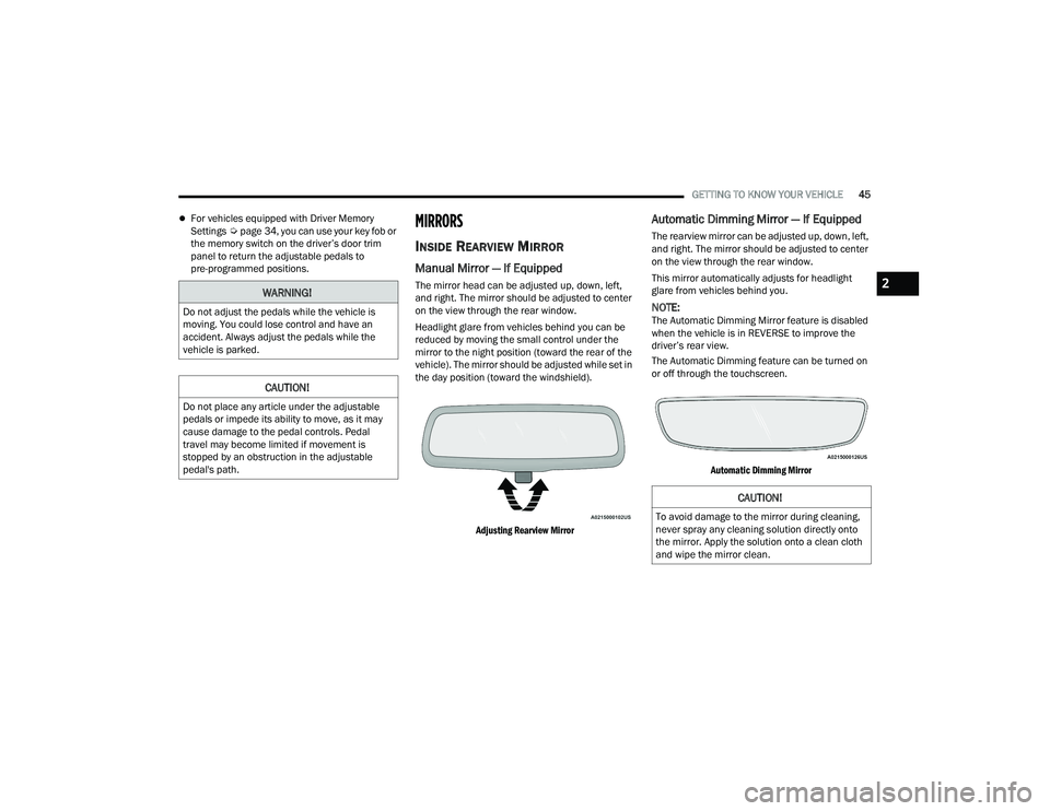
The mirror head can be adjusted up, down, left,
and right. The mirror should be adjusted to center
on the view through the rear window.
Headlight glare from vehicles behind you can be
reduced by moving the small control under the
mirror to the night position (toward the rear of the
vehicle). The mirror should be adjusted while set in
the day position (toward the windshield).
Adjusting Rearview Mirror
Automatic Dimming Mirror — If Equipped
The rearview mirror can be adjusted up, down, left,
and right. The mirror should be adjusted to center
on the view through the rear window.
This mirror automatically adjusts for headlight
glare from vehicles behind you.
NOTE:The Automatic Dimming Mirror feature is disabled
when the vehicle is in REVERSE to improve the
driver’s rear view.
The Automatic Dimming feature can be turned on
or off through the touchscreen.
Automatic Dimming Mirror
WARNING!
Do not adjust the pedals while the vehicle is
moving. You could lose control and have an
accident. Always adjust the pedals while the
vehicle is parked.
CAUTION!
Do not place any article under the adjustable
pedals or impede its ability to move, as it may
cause damage to the pedal controls. Pedal
travel may become limited if movement is
stopped by an obstruction in the adjustable
pedal's path.
CAUTION!
To avoid damage to the mirror during cleaning,
never spray any cleaning solution directly onto
the mirror. Apply the solution onto a clean cloth
and wipe the mirror clean.
2
22_DT_OM_EN_USC_t.book Page 45
Page 50 of 496
48GETTING TO KNOW YOUR VEHICLE
POWER MIRRORS
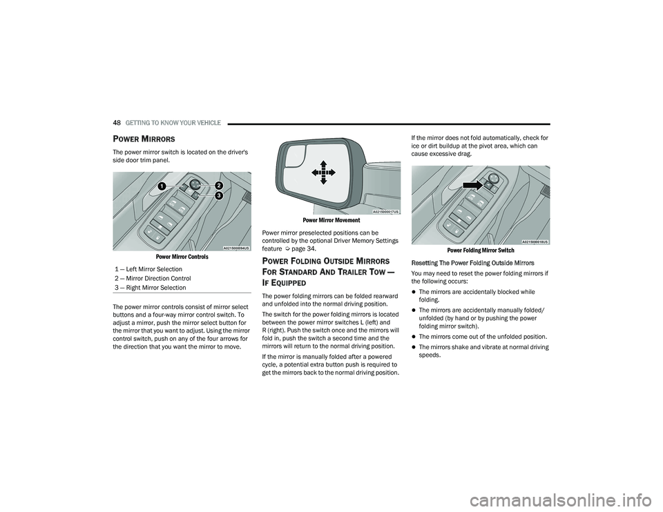
The power mirror switch is located on the driver's
side door trim panel.
Power Mirror Controls
The power mirror controls consist of mirror select
buttons and a four-way mirror control switch. To
adjust a mirror, push the mirror select button for
the mirror that you want to adjust. Using the mirror
control switch, push on any of the four arrows for
the direction that you want the mirror to move.
Power Mirror Movement
Power mirror preselected positions can be
controlled by the optional Driver Memory Settings
feature Ú page 34.
POWER FOLDING OUTSIDE MIRRORS
F
OR STANDARD AND TRAILER TOW —
I
F EQUIPPED
The power folding mirrors can be folded rearward
and unfolded into the normal driving position.
The switch for the power folding mirrors is located
between the power mirror switches L (left) and
R (right). Push the switch once and the mirrors will
fold in, push the switch a second time and the
mirrors will return to the normal driving position.
If the mirror is manually folded after a powered
cycle, a potential extra button push is required to
get the mirrors back to the normal driving position. If the mirror does not fold automatically, check for
ice or dirt buildup at the pivot area, which can
cause excessive drag.
Power Folding Mirror Switch
Resetting The Power Folding Outside Mirrors
You may need to reset the power folding mirrors if
the following occurs:The mirrors are accidentally blocked while
folding.
The mirrors are accidentally manually folded/
unfolded (by hand or by pushing the power
folding mirror switch).
The mirrors come out of the unfolded position.
The mirrors shake and vibrate at normal driving
speeds.
1 — Left Mirror Selection
2 — Mirror Direction Control
3 — Right Mirror Selection
22_DT_OM_EN_USC_t.book Page 48
Page 62 of 496
60GETTING TO KNOW YOUR VEHICLE
NOTE:The courtesy/reading lights will remain on until the
switch is pushed a second time, so be sure they
have been turned off before exiting the vehicle. If
the interior lights are left on after the ignition is
turned off, they will automatically turn off after
10 minutes.
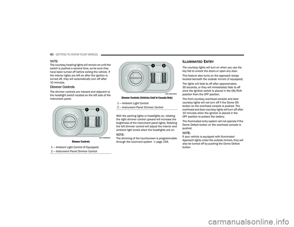
Dimmer Controls
The dimmer controls are inboard and adjacent to
the headlight switch located on the left side of the
instrument panel.
Dimmer Controls Dimmer Controls (Vehicles Sold In Canada Only)
With the parking lights or headlights on, rotating
the right dimmer control upward will increase the
brightness of the instrument panel lights. Rotating
the left dimmer control will adjust the interior and
ambient light levels when the headlights are on.
NOTE:The dimming of the touchscreen is programmable
through the Uconnect system Ú page 234.
ILLUMINATED ENTRY
The courtesy lights will turn on when you use the
key fob to unlock the doors or open any door.
This feature also turns on the approach lamps
located beneath the outside mirrors (if equipped).
The lights will fade to off after approximately
30 seconds, or they will immediately fade to off
once the ignition switch is placed in the ON/RUN
position from the OFF position.
The front courtesy overhead console and door
courtesy lights will not turn off if the Dome ON
button on the overhead console is pushed. The
overhead and door courtesy lights will turn off after
10 minutes when the ignition is placed in the
OFF position to protect the battery.
The illuminated entry system will not operate if the
Dome Defeat button on the overhead console is
pushed.
NOTE:If your vehicle is equipped with Illuminated
Approach lights under the outside mirrors, they will
also be turned off by pushing the Dome Defeat
button.
1 — Ambient Light Control (If Equipped)
2 — Instrument Panel Dimmer Control
1 — Ambient Light Control
2 — Instrument Panel Dimmer Control
22_DT_OM_EN_USC_t.book Page 60
Page 68 of 496
66GETTING TO KNOW YOUR VEHICLE
A/C Button
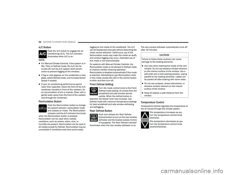
Push the A/C button to engage the Air
Conditioning (A/C). The A/C indicator
illuminates when A/C is on.
NOTE:
For Manual Climate Controls, if the system is in
Mix, Floor or Defrost mode, the A/C can be
turned off, but the A/C system shall remain
active to prevent fogging of the windows.
If fog or mist appears on the windshield or side
glass, select Defrost mode, and increase blower
speed if needed.
If your air conditioning performance seems
lower than expected, check the front of the A/C
condenser (located in front of the radiator), for
an accumulation of dirt or insects. Clean with a
gentle water spray from the front of the radiator
and through the condenser.
Recirculation Button
Push the Recirculation button to change
the system between recirculation mode
and outside air mode. The Recirculation
indicator and the A/C indicator illuminate
when the Recirculation button is pressed.
Recirculation can be used when outside
conditions, such as smoke, odors, dust, or
humidity are present. Recirculation can be used in
all modes except for Defrost. Recirculation may be
unavailable if conditions exist that could create fogging on the inside of the windshield. The A/C
can be deselected manually without disturbing the
mode control selection. Continuous use of the
Recirculation mode may make the inside air stuffy
and window fogging may occur. Extended use of
this mode is not recommended.
On systems with Manual Climate Controls, the
Recirculation mode is not allowed in Defrost mode
to improve window cleaning operation.
Recirculation is disabled automatically if this mode
is selected. Attempting to use Recirculation while
in this mode causes the LED in the control button
to blink and then turn off.
Front Defrost Setting
Turn the mode control knob to the Front
Defrost mode setting. Air comes from the
windshield and side window demist
outlets. When the defrost button is
selected, the blower level may increase. Use
Defrost mode with maximum temperature settings
for best windshield and side window defrosting
and defogging.
Rear Defrost Button
Push and release the Rear Defrost
Control button to turn on the rear window
defroster and the heated outside mirrors
(if equipped). The Rear Defrost indicator
illuminates when the rear window defroster is on. The rear window defroster automatically turns off
after 10 minutes.
Temperature Control
Temperature Control regulates the temperature of
the air forced through the climate system.
The temperature increases as you
turn the temperature control knob
clockwise.
The temperature decreases as you
turn the temperature control knob
counterclockwise.
CAUTION!
Failure to follow these cautions can cause
damage to the heating elements:
Use care when washing the inside of the rear
window. Do not use abrasive window cleaners
on the interior surface of the window. Use a
soft cloth and a mild washing solution, wiping
parallel to the heating elements. Labels can
be peeled off after soaking with warm water.
Do not use scrapers, sharp instruments, or
abrasive window cleaners on the interior
surface of the window.
Keep all objects a safe distance from the
window.
22_DT_OM_EN_USC_t.book Page 66
Page 142 of 496
140 (Continued)
STARTING AND OPERATING
STARTING THE ENGINE
GASOLINE ENGINE
Before starting your vehicle, adjust your seat,
adjust both inside and outside mirrors, and fasten
your seat belt.
The starter should not be operated for more than
10-second intervals. Waiting at least 10 to 15
seconds between such intervals will protect the
starter from overheating. DIESEL ENGINE
Before starting your vehicle, adjust your seat, both
inside and outside mirrors, and fasten your seat
belts.
The starter is allowed to crank for up to 25-second
intervals. Waiting at least two minutes between
such intervals will protect the starter from
overheating.
WARNING!
When leaving the vehicle, always make sure
the keyless ignition node is in the OFF posi-
tion, remove the key fob from the vehicle and
lock the vehicle.
Never leave children alone in a vehicle, or with
access to an unlocked vehicle. Allowing chil -
dren to be in a vehicle unattended is
dangerous for a number of reasons. A child or
others could be seriously or fatally injured.
Children should be warned not to touch the
parking brake, brake pedal or the gear
selector.
Do not leave the key fob in or near the vehicle,
or in a location accessible to children, and do
not leave the ignition of a vehicle equipped
with Keyless Enter ‘n Go™ in the ACC or
ON/RUN position. A child could operate power
windows, other controls, or move the vehicle.
Do not leave children or animals inside parked
vehicles in hot weather. Interior heat buildup
may cause serious injury or death.
WARNING!WARNING!
Before exiting a vehicle, always come to a
complete stop, then shift the automatic trans -
mission into PARK and apply the parking brake.
Always make sure the ENGINE START/STOP
button is in the OFF position, key fob is removed
from the vehicle and vehicle is locked.
Never leave children alone in a vehicle, or with
access to an unlocked vehicle. Leaving chil -
dren in a vehicle unattended is dangerous for
a number of reasons. A child or others could
be seriously or fatally injured. Children should
be warned not to touch the parking brake,
brake pedal or the gear selector.
Do not leave the key fob in or near the vehicle,
or in a location accessible to children, and do
not leave the ignition of a vehicle equipped
with Keyless Enter ‘n Go™ in the ACC or ON/
RUN position. A child could operate power
windows, other controls, or move the vehicle.
Do not leave children or animals inside parked
vehicles in hot weather. Interior heat buildup
may cause serious injury or death.
22_DT_OM_EN_USC_t.book Page 140
Page 203 of 496
STARTING AND OPERATING201
If the camera delay is turned on, the camera image
will display for up to 10 seconds after shifting out
of REVERSE. The camera image will stop
displaying, close, and display the previous screen
if the vehicle speed exceeds 8 mph (13 km/h), the
vehicle is shifted into PARK, or the ignition is
placed in the OFF position. The X button on the
touchscreen disables the display of the camera
image.
If the camera delay is turned off, the camera image
will close and display the previous screen after
shifting out of REVERSE.
If active guidelines are enabled, the lines are
overlaid on the image in the Rear View and Top
View to illustrate the width of the vehicle and its
projected path based on steering wheel position.
The guidelines have different colored zones to
indicate the distance an object in the view is from
the rear of the vehicle. Refer to the chart below: Modes Of Operation
Standard Rear View can be manually activated by
selecting “Back Up Camera” through the Controls
menu within the Uconnect system.
Top View
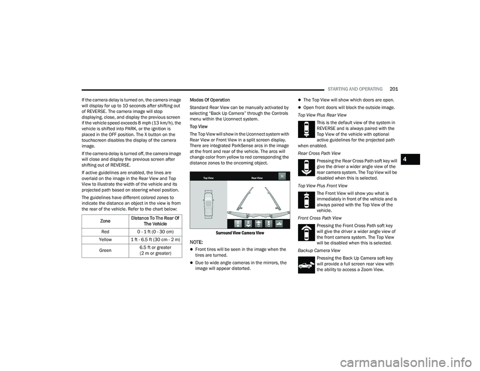
The Top View will show in the Uconnect system with
Rear View or Front View in a split screen display.
There are integrated ParkSense arcs in the image
at the front and rear of the vehicle. The arcs will
change color from yellow to red corresponding the
distance zones to the oncoming object.
Surround View Camera View
NOTE:
Front tires will be seen in the image when the
tires are turned.
Due to wide angle cameras in the mirrors, the
image will appear distorted.
The Top View will show which doors are open.
Open front doors will block the outside image.
Top View Plus Rear View This is the default view of the system in
REVERSE and is always paired with the
Top View of the vehicle with optional
active guidelines for the projected path
when enabled.
Rear Cross Path View
Pressing the Rear Cross Path soft key will
give the driver a wider angle view of the
rear camera system. The Top View will be
disabled when this is selected.
Top View Plus Front View The Front View will show you what is
immediately in front of the vehicle and is
always paired with the Top View of the
vehicle.
Front Cross Path View Pressing the Front Cross Path soft key
will give the driver a wider angle view of
the front camera system. The Top View
will be disabled when this is selected.
Backup Camera View Pressing the Back Up Camera soft key
will provide a full screen rear view with
the ability to access a Zoom View.
Zone
Distance To The Rear Of
The Vehicle
Red 0 - 1 ft (0 - 30 cm)
Yellow 1 ft - 6.5 ft (30 cm - 2 m)
Green 6.5 ft or greater
(2 m or greater)
4
22_DT_OM_EN_USC_t.book Page 201
Page 321 of 496

SAFETY319
Rain Brake Support (RBS)
RBS may improve braking performance in wet
conditions. It will periodically apply a small amount
of brake pressure to remove any water buildup on
the front brake rotors. It functions when the
windshield wipers are in LO or HI speed. When Rain
Brake Support is active, there is no notification to
the driver and no driver interaction is required.
Ready Alert Braking (RAB)
RAB may reduce the time required to reach full
braking during emergency braking situations. It
anticipates when an emergency braking situation
may occur by monitoring how fast the throttle is
released by the driver. The Electronic Brake
Control system will prepare the brake system for a
panic stop.
Traction Control System (TCS)
The TCS monitors the amount of wheel spin of
each of the driven wheels. If wheel spin is
detected, the TCS may apply brake pressure to the
spinning wheel(s) and/or reduce engine power to
provide enhanced acceleration and stability. A
feature of the TCS, Brake Limited Differential (BLD)
functions similarly to a limited slip differential and
controls the wheel spin across a driven axle. If one
wheel on a driven axle is spinning faster than the
other, the system will apply the brake of the spinning wheel. This will allow more engine torque
to be applied to the wheel that is not spinning. BLD
may remain enabled even if TCS and Electronic
Stability Control (ESC) are in reduced modes.
Trailer Sway Control (TSC)
TSC uses sensors in the vehicle to recognize an
excessively swaying trailer and will take the
appropriate actions to attempt to stop the sway.
NOTE:TSC cannot stop all trailers from swaying. Always
use caution when towing a trailer and follow the
trailer tongue weight recommendations
Ú
page 212.
When TSC is functioning, the ESC Activation/
Malfunction Indicator Light will flash, the engine
power may be reduced and you may feel the
brakes being applied to individual wheels to
attempt to stop the trailer from swaying. TSC is
disabled when the ESC system is in the “Partial
Off” or “Full Off” modes.
AUXILIARY DRIVING SYSTEMS
BLIND SPOT MONITORING (BSM) —
I
F EQUIPPED
BSM uses two radar sensors, located inside the
taillights, to detect highway licensable vehicles
(automobiles, trucks, motorcycles, etc.) that enter
the blind spot zones from the rear/front/side of
the vehicle.
Rear Detection Zones
When the vehicle is started, the BSM Warning Light
will momentarily illuminate in both outside
rearview mirrors to let the driver know that the
system is operational. The BSM system sensors
operate when the vehicle is in any forward gear
and enters standby mode when the vehicle is in
PARK.
WARNING!
If TSC activates while driving, slow the vehicle
down, stop at the nearest safe location, and
adjust the trailer load to eliminate trailer sway.
6
22_DT_OM_EN_USC_t.book Page 319
Page 487 of 496
485
Heater, Engine Block
..................................... 149High Beam/Low Beam Select
(Dimmer) Switch.............................................. 55Hill Descent Control............................. 137, 316Hill Descent Control Indicator........................ 316Hill Start Assist.............................................. 318Hitches Trailer Towing............................................ 216HomeLink (Garage Door Opener).................... 49HoodOpening..................................................... 130Hood Release.................................................. 85HUD..................................................... 121, 122
I
Ignition............................................................ 23Switch......................................................... 23Ignition Park Interlock.................................... 154Illuminated Entry............................................. 60Inside Rearview Mirror............................ 45, 372Instrument
Cluster............ 106, 108, 110, 111, 113, 114Descriptions.................. 107, 109, 111, 114Display...................................................... 114Engine Oil Reset........................................ 116Location And Controls............................... 115Menu Items............................................... 116
Instrument Cluster DisplayAudio........................................................ 121Driver Assist............................................. 117Fuel Economy........................................... 120Off-Road................................................... 117Speedometer............................................ 116StopStart.................................................. 120Stored Messages...................................... 121Trailer Tow................................................ 121Trip........................................................... 120Vehicle Info............................................... 116Instrument Panel Lens Cleaning................... 465Integrated Trailer Brake Control................... 221Interior Appearance Care.............................. 464Interior Lights................................................... 59Intervention Regeneration Strategy..... 124, 414Inverter Outlet (115V)...................................... 77
J
Jack Location................................................ 375Jump Starting............................................... 384
K
Key Fob............................................................ 19Programming Additional Key Fobs............... 22Key Fob Battery Replacement......................... 21
Key Fob Programming
(Remote Keyless Entry)....................................22Keyless Enter-N-Go................................ 30, 141Passive Entry...............................................30Keys.................................................................19
L
Lane Change Assist..........................................57LaneSense........................ 132, 136, 137, 196Lap/Shoulder Belts....................................... 336Latches......................................................... 370Hood............................................................85Lead Free Gasoline....................................... 467Leaks, Fluid................................................... 370Life Of Tires................................................... 454Light Bulbs........................................... 370, 438Lights............................................................ 3704WD.......................................................... 1354WD AUTO................................................ 1374WD High................................................. 1354WD Low.................................................. 135Air Bag.................................... 128, 342, 368Air Suspension Aerodynamic Height......... 134Air Suspension Fault................................. 131Air Suspension Off-Road 1........................ 134Air Suspension Off-Road 2........................ 134
11
22_DT_OM_EN_USC_t.book Page 485