RAM 1500 2023 Owners Manual
Manufacturer: RAM, Model Year: 2023, Model line: 1500, Model: RAM 1500 2023Pages: 416, PDF Size: 20.59 MB
Page 91 of 416
GETTING TO KNOW YOUR VEHICLE89
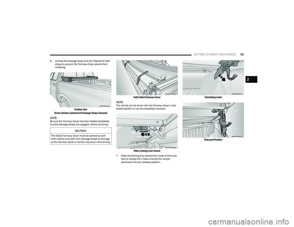
6. Unsnap the stowage strap and clip. Repeat for both
straps to prevent the Tonneau Cover panels from
unfolding.
Position One
(Front Latches Latched And Stowage Straps Secured)
NOTE:
Be sure the Tonneau Cover has been folded completely,
and the stowage straps are engaged, before removing.
Fully Folded Tonneau Cover
NOTE:
The vehicle can be driven with the Tonneau Cover in the
folded position or can be completely removed.
Slide Locking Lever Inward
7. Slide the locking lever toward the inside of the truck bed to release the J Hook and pull the handle
downward into the released position.
Unlatching Latch
Released Position
CAUTION!
The folded Tonneau Cover must be latched by both
front latches and both front stowage straps or damage
to the Tonneau Cover or vehicle may occur while driving.
2
23_DT_OM_EN_USC_t.book Page 89
Page 92 of 416
90GETTING TO KNOW YOUR VEHICLE
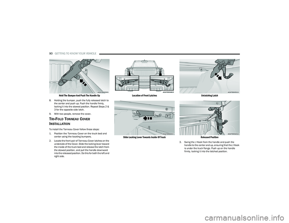
Hold The Bumper And Push The Handle Up
8. Holding the bumper, push the fully released latch to
the center and push up. Push the handle firmly,
locking it into the stowed position. Repeat Steps 2 &
3 for the opposite side latch.
9. With two people, remove the cover.
TRI-FOLD TONNEAU COVER
I
NSTALLATION
To install the Tonneau Cover follow these steps:
1. Position the Tonneau Cover on the truck bed and
center using the locating bumpers.
2. Locate the front pair of Tonneau Cover latches on the underside of the Cover. Slide the locking lever toward
the inside of the truck bed and release the latch from
the stowed position, and pull the handle downward
into the released position. Do this for both the left and
right side.
Location of Front Latches
Slide Locking Lever Towards Inside Of Truck Unlatching Latch
Released Position
3. Swing the J Hook from the handle and push the handle to the center and up, ensuring that the J Hook
is under the truck flange. Push up on the handle
firmly, locking it into the latched position.
23_DT_OM_EN_USC_t.book Page 90
Page 93 of 416
GETTING TO KNOW YOUR VEHICLE91
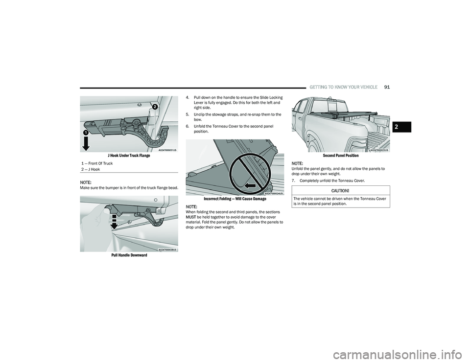
J Hook Under Truck Flange
NOTE:
Make sure the bumper is in front of the truck flange bead.
Pull Handle Downward
4. Pull down on the handle to ensure the Slide Locking Lever is fully engaged. Do this for both the left and
right side.
5. Unclip the stowage straps, and re-snap them to the bow.
6. Unfold the Tonneau Cover to the second panel position.
Incorrect Folding — Will Cause Damage
NOTE:
When folding the second and third panels, the sections
MUST be held together to avoid damage to the cover
material. Fold the panel gently. Do not allow the panels to
drop under their own weight.
Second Panel Position
NOTE:
Unfold the panel gently, and do not allow the panels to
drop under their own weight.
7. Completely unfold the Tonneau Cover.
1 — Front Of Truck
2 — J Hook
CAUTION!
The vehicle cannot be driven when the Tonneau Cover
is in the second panel position.
2
23_DT_OM_EN_USC_t.book Page 91
Page 94 of 416
92GETTING TO KNOW YOUR VEHICLE
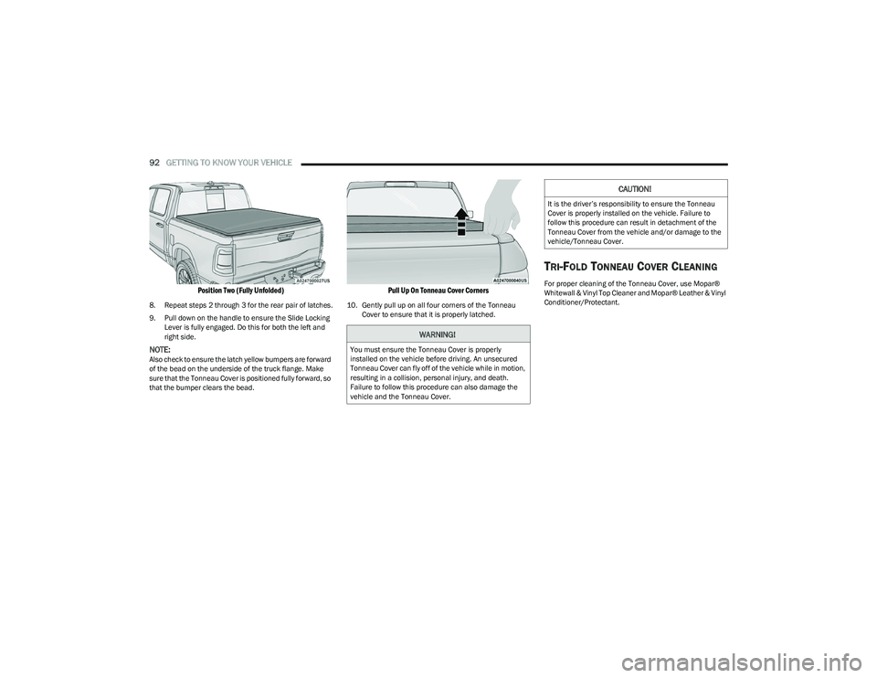
Position Two (Fully Unfolded)
8. Repeat steps 2 through 3 for the rear pair of latches.
9. Pull down on the handle to ensure the Slide Locking
Lever is fully engaged. Do this for both the left and
right side.
NOTE:Also check to ensure the latch yellow bumpers are forward
of the bead on the underside of the truck flange. Make
sure that the Tonneau Cover is positioned fully forward, so
that the bumper clears the bead.
Pull Up On Tonneau Cover Corners
10. Gently pull up on all four corners of the Tonneau Cover to ensure that it is properly latched.
TRI-FOLD TONNEAU COVER CLEANING
For proper cleaning of the Tonneau Cover, use Mopar®
Whitewall & Vinyl Top Cleaner and Mopar® Leather & Vinyl
Conditioner/Protectant.
WARNING!
You must ensure the Tonneau Cover is properly
installed on the vehicle before driving. An unsecured
Tonneau Cover can fly off of the vehicle while in motion,
resulting in a collision, personal injury, and death.
Failure to follow this procedure can also damage the
vehicle and the Tonneau Cover.
CAUTION!
It is the driver’s responsibility to ensure the Tonneau
Cover is properly installed on the vehicle. Failure to
follow this procedure can result in detachment of the
Tonneau Cover from the vehicle and/or damage to the
vehicle/Tonneau Cover.
23_DT_OM_EN_USC_t.book Page 92
Page 95 of 416
93
GETTING TO KNOW YOUR INSTRUMENT PANEL
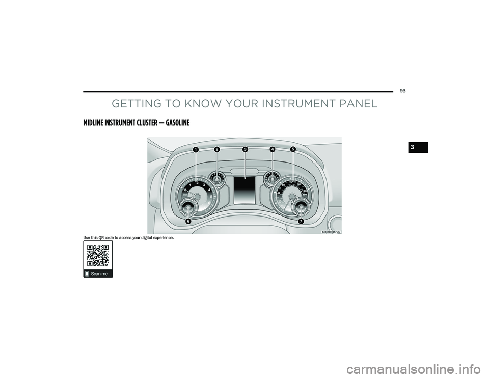
MIDLINE INSTRUMENT CLUSTER — GASOLINE
Use this QR code to access your digital experience.
3
23_DT_OM_EN_USC_t.book Page 93
Page 96 of 416
94GETTING TO KNOW YOUR INSTRUMENT PANEL
MIDLINE INSTRUMENT CLUSTER
D
ESCRIPTIONS — GASOLINE
1. Tachometer
Indicates the engine speed in revolutions per
minute (RPM x 1000).
2. Voltmeter When the vehicle is in the RUN state, the gauge
indicates the electrical system voltage. The
pointer should stay within the normal range if the
battery is charged. If the pointer moves to either
extreme left or right and remains there during
normal driving, the electrical system should be
serviced.
NOTE:In vehicles equipped with Stop/Start, a reduced voltage
may be present during an Autostop.
3. Instrument Cluster Display
When the appropriate conditions exist, this display
shows the instrument cluster display messages
Úpage 98.
The display always shows one of the main menu
items after ignition on. 4. Oil Pressure Gauge
The pointer should always indicate the oil pres -
sure when the engine is running. A continuous
high or low reading under normal driving condi -
tions may indicate a lubrication system malfunc -
tion. Immediate service should be obtained from
an authorized dealer.
NOTE:In vehicles equipped with Stop/Start, an oil pressure indi -
cation of zero is normal during an Autostop.
5. Speedometer
Indicates vehicle speed.
6. Temperature Gauge The pointer shows engine coolant temperature.
The pointer positioned within the normal range
indicates that the engine cooling system is oper -
ating satisfactorily.
The pointer will likely indicate a higher tempera -
ture when driving in hot weather, up mountain
grades, or when towing a trailer. It should not be
allowed to exceed the upper limits of the normal
operating range. 7. Fuel Gauge
The pointer shows the level of fuel in the fuel tank
when the ignition is in the ON/RUN position.
The fuel pump symbol points to the
side of the vehicle where the fuel door
is located.
WARNING!
A hot engine cooling system is dangerous. You or others
could be badly burned by steam or boiling coolant.
You may want to call an authorized dealer for service if
your vehicle overheats
Úpage 350.
CAUTION!
Driving with a hot engine cooling system could damage
your vehicle. If the temperature gauge reads “H,” pull
over and stop the vehicle. Idle the vehicle with the air
conditioner turned off until the pointer drops back into
the normal range. If the pointer remains on the “H,”
turn the engine off immediately and call an authorized
dealer for service.
23_DT_OM_EN_USC_t.book Page 94
Page 97 of 416
GETTING TO KNOW YOUR INSTRUMENT PANEL95
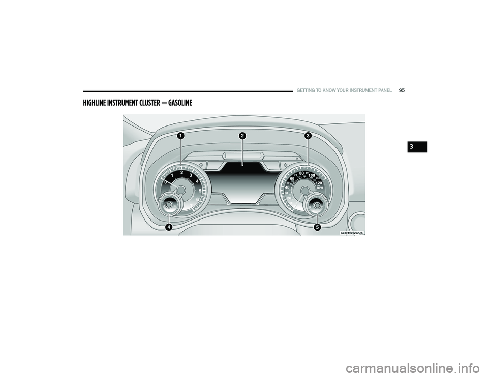
HIGHLINE INSTRUMENT CLUSTER — GASOLINE
3
23_DT_OM_EN_USC_t.book Page 95
Page 98 of 416
96GETTING TO KNOW YOUR INSTRUMENT PANEL
HIGHLINE INSTRUMENT CLUSTER
D
ESCRIPTIONS — GASOLINE
1. Tachometer
Indicates the engine speed in revolutions per
minute (RPM x 1000).
2. Instrument Cluster Display When the appropriate conditions exist, this display
shows the instrument cluster display messages
Úpage 98.
The display always shows one of the main menu
items after ignition on.
3. Speedometer Indicates vehicle speed. 4. Temperature Gauge
The pointer shows engine coolant temperature.
The pointer positioned within the normal range
indicates that the engine cooling system is oper -
ating satisfactorily.
The pointer will likely indicate a higher tempera -
ture when driving in hot weather, up mountain
grades, or when towing a trailer. It should not be
allowed to exceed the upper limits of the normal
operating range. 5. Fuel Gauge
The pointer shows the level of fuel in the fuel tank
when the ignition is in the ON/RUN position.
The fuel pump symbol points to the
side of the vehicle where the fuel door
is located.WARNING!
A hot engine cooling system is dangerous. You or others
could be badly burned by steam or boiling coolant. You
may want to call an authorized dealer for service if your
vehicle overheats
Úpage 350.
CAUTION!
Driving with a hot engine cooling system could damage
your vehicle. If the temperature gauge reads “H,” pull
over and stop the vehicle. Idle the vehicle with the air
conditioner turned off until the pointer drops back into
the normal range. If the pointer remains on the “H,”
turn the engine off immediately and call an authorized
dealer for service.
23_DT_OM_EN_USC_t.book Page 96
Page 99 of 416
GETTING TO KNOW YOUR INSTRUMENT PANEL97
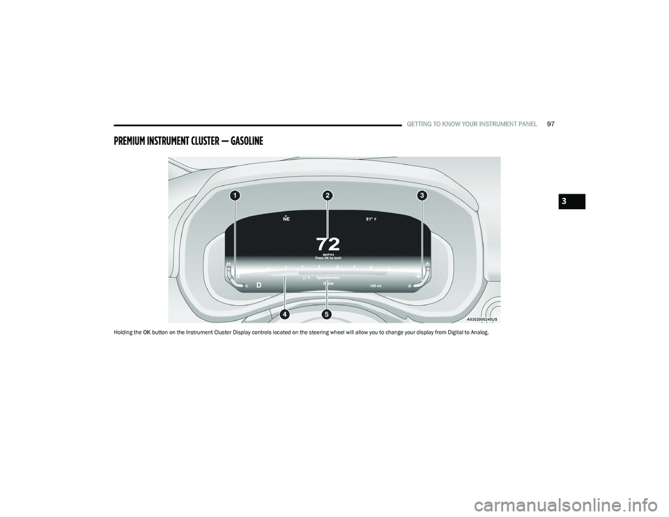
PREMIUM INSTRUMENT CLUSTER — GASOLINE
Holding the OK button on the Instrument Cluster Display controls located on the steering wheel will allow you to change your display from Digital to Analog.
3
23_DT_OM_EN_USC_t.book Page 97
Page 100 of 416
98GETTING TO KNOW YOUR INSTRUMENT PANEL
PREMIUM INSTRUMENT CLUSTER
D
ESCRIPTIONS — GASOLINE
1. Temperature Gauge
The temperature gauge shows engine coolant
temperature. Any reading within 203°F - 230°F
(95°C - 110°C) indicates that the engine cooling
system is operating satisfactorily.
The pointer will likely indicate a higher tempera -
ture when driving in hot weather, up mountain
grades, or when towing a trailer. It should not be
allowed to exceed the upper limits of the normal
operating range. 2. Speedometer
Indicates vehicle speed.
3. Fuel Gauge The pointer shows the level of fuel in the fuel tank
when the Keyless Push Button Ignition is in the
ON/RUN position.
The fuel pump symbol points to the
side of the vehicle where the fuel door
is located.
4. Tachometer Indicates the engine speed in revolutions per
minute (RPM x 1000).
5. Instrument Cluster Display The instrument cluster display features a driver
interactive display
Úpage 98.
NOTE:The hard telltales will illuminate for a bulb check when the
ignition is first cycled.
INSTRUMENT CLUSTER DISPLAY
Depending on your vehicles trim level, features and
options may vary.
Your vehicle will be equipped with an instrument cluster
display, which offers useful information to the driver. With
the ignition in the OFF mode, opening/closing of a door will
activate the display for viewing, and display the total miles,
or kilometers, in the odometer. Your instrument cluster
display is designed to display important information about
your vehicle’s systems and features. Using a driver interactive display located on the
instrument panel, your instrument cluster display can
show you how systems are working and give you warnings
when they are not. The steering wheel mounted controls
allow you to scroll through the main menus and
submenus. You can access the specific information you
want and make selections and adjustments.
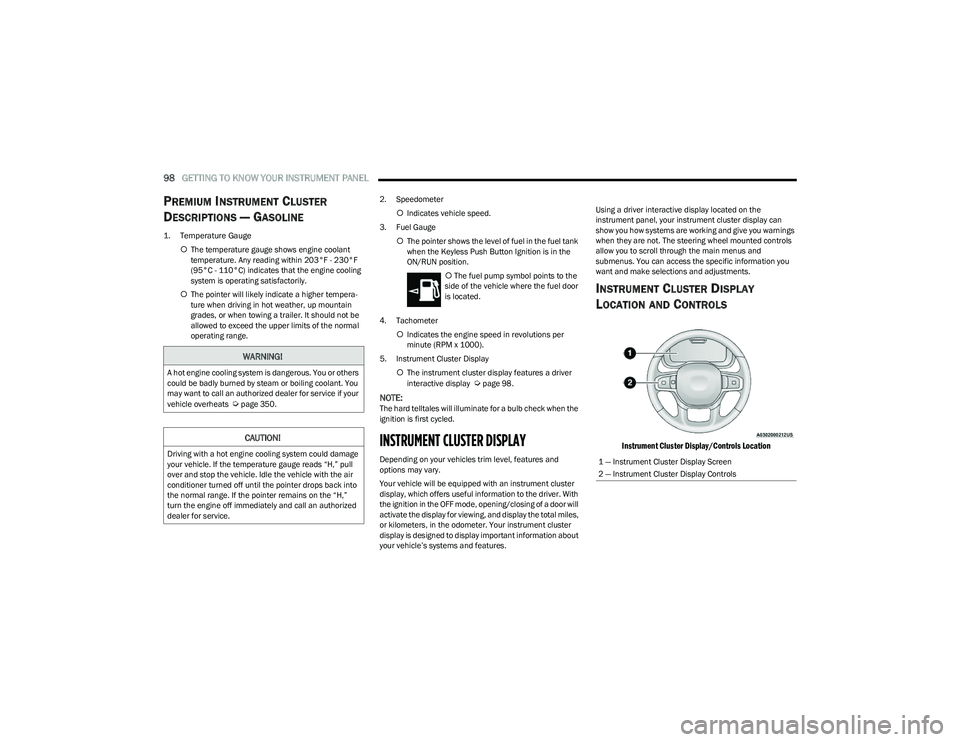
INSTRUMENT CLUSTER DISPLAY
L
OCATION AND CONTROLS
Instrument Cluster Display/Controls Location
WARNING!
A hot engine cooling system is dangerous. You or others
could be badly burned by steam or boiling coolant. You
may want to call an authorized dealer for service if your
vehicle overheats
Úpage 350.
CAUTION!
Driving with a hot engine cooling system could damage
your vehicle. If the temperature gauge reads “H,” pull
over and stop the vehicle. Idle the vehicle with the air
conditioner turned off until the pointer drops back into
the normal range. If the pointer remains on the “H,”
turn the engine off immediately and call an authorized
dealer for service.1 — Instrument Cluster Display Screen
2 — Instrument Cluster Display Controls
23_DT_OM_EN_USC_t.book Page 98