display RAM 1500 2023 Owners Manual
[x] Cancel search | Manufacturer: RAM, Model Year: 2023, Model line: 1500, Model: RAM 1500 2023Pages: 416, PDF Size: 20.59 MB
Page 282 of 416

280SAFETY
The system will be activated when a positive increase in
tire pressure is detected by the TPMS while inflating the
tire. The ignition must be in the RUN mode, with the
transmission in PARK.
NOTE:It is not required to have the engine running to enter Tire
Fill Alert mode.
The hazard lamps will come on to confirm the vehicle is in
Tire Fill Alert mode.
When Tire Fill Alert mode is entered, the tire pressure
display screen will be displayed in the instrument cluster.
If the hazard lamps do not come on while inflating the tire,
the TPMS sensor may be out of range preventing the TPMS
sensor signal from being received. In this case, the vehicle
may need to be moved either forward or backward slightly
to exit the null spot.
Operation:
The horn will sound once to let the user know when to
stop filling the tire, when it reaches recommended
pressure.
The horn will sound three times if the tire is overfilled
and will continue to sound every five seconds if the
user continues to inflate the tire.
The horn will sound once again when enough air is let
out to reach proper inflation level.
The horn will also sound three times if the tire is then
underinflated and will continue to sound every five
seconds if the user continues to deflate the tire.
Trailer Tire Pressure Monitoring System
(TTPMS) — If Equipped
The Trailer Tire Pressure Monitoring System (TTPMS) is a
feature that displays the trailer tire pressure values and
warns the driver of a low tire pressure event based on the
driver’s set target tire pressure value, through TTPMS
settings found in the radio.
The TTPMS monitors the pressure of each tire and warns
the driver through the instrument cluster, when either a
low tire pressure condition falls below 25% of the driver’s
set pressure or if a system malfunction occurs. The
instrument cluster will display the actual tire pressure or
dashes for each of the trailer tires in the correct trailer
position, based on trailer configuration. The TTPMS can
support up to 12 trailer tires per configured trailer on up to
four configurable trailers
Úpage 191.
Trailer Tire Pressure Monitoring System
Trailer Tire Pressure Sensor Pairing
In order use this feature, the provided tire pressure
sensors must be installed in the desired trailer tires and
the sensors must be paired to the truck. If the target trailer
requires more than the provided four sensors, additional
sensors can be purchased at an authorized Ram
dealership.
With the sensors installed and the trailer near or
connected to your Ram truck, initiate the pairing process
by entering the settings menu in the radio and selecting
trailer. Select the desired trailer profile to pair to, open the
“Tire Pressure” menu, and hit “Setup All Tires”
Úpage 191.
NOTE:The vehicle may not be driven until the pairing process is
complete.
Trailer Tire Pressure Settings
23_DT_OM_EN_USC_t.book Page 280
Page 283 of 416

SAFETY281
Trailer Tire Pressure Pairing
Follow the on screen prompts to select the number of
axles (1-3), the number of trailer tires (2, 4, 6, 8, or 12),
and the set trailer tire pressure. The range is selectable
anywhere between 25-125 psi (172-862 kPa).
Once psi (kPa) is programmed, the pairing screen
appears. Tire sensors must be paired in order shown.
Starting with Tire 1, deflate tire by 5 psi (34 kPa) and wait
for a horn chirp. It may take up to three minutes for the
chirp to occur, indicating that the sensor has paired.
Repeat process on each tire, in order, until complete.
Do not exit the pairing screen until process is complete.
If pairing was unsuccessful, a double horn chirp will
sound, and a prompt on the touchscreen will allow you to
retry the procedure; “Retry” will only appear when setup
fails. Each tire must be successfully paired during a single
pairing process to receive the success screen.
NOTE:If the pairing process times out after three minutes of no
communication with a sensor, a double horn chip will
occur indicating the pairing has failed and a message will
display on the radio indicating the process was unsuc -
cessful. Under certain circumstances, the double horn
chirp may continue to happen every three minutes indi -
cating the failed pairing. If this happens, the horn chirping
may be canceled by cycling the ignition button OFF and
then back to RUN position.
Tire Pressure Monitoring System Low Pressure Warnings
When a tire pressure low in one or more of the active road
tires is detected, the instrument cluster will display a
message stating “Trailer Tire Pressure Low”.
The instrument cluster will then display the TTPMS graphic
showing the pressure values of each tire with the low tire
pressure values in a different color.
Should this occur, you should stop as soon as possible
and inflate the tires with a low pressure condition (those in
a different color in the instrument cluster graphic) to the
customer programmed target tire pressure value as
shown at the top of the TTPMS instrument cluster graphic.
Once the tire(s) are inflated, the system will automatically
update the graphic display in the instrument cluster,
returning to its original color. The vehicle may need to be
driven for up to 10 minutes above 15 mph (24 km/h) in
order for the TTPMS to receive the updated information. Service TTPMS Warning
If a system fault is detected, the instrument cluster will
display a “Trailer Tire Pressure System Service Required”
message for a minimum of five seconds.
Once the system fault is corrected the "Trailer Tire
Pressure System Service Required" message will no
longer be displayed. The vehicle may need to be driven for
up to 10 minutes above 15 mph (24 km/h) in order for the
TTPMS to receive the trailer tire pressure information.
Trailer Tire Pressure System Not Configured
A “Trailer Tire Pressure System Not Configured” message
will be displayed in the instrument cluster on the TTPMS
instrument cluster graphic when a trailer number is
selected that has not had trailer tire pressure sensors
paired. To correct this condition, see
Úpage 191.
Trailer Sensors Detected Do Not Match Active Trailer
The “Trailer Sensors Detected Do Not Match Active
Trailer” message will be displayed in the instrument
cluster when the trailer sensors being received by the
TTPMS module do not match the trailer sensors paired to
the current trailer number selected. This message will be
displayed when the sensors being received completely
match the sensors paired to another trailer number
configured in the TTPMS module.
To correct this condition, the correct trailer number must
be selected in the radio
Úpage 191.
6
23_DT_OM_EN_USC_t.book Page 281
Page 316 of 416

314
IN CASE OF EMERGENCY
HAZARD WARNING FLASHERS
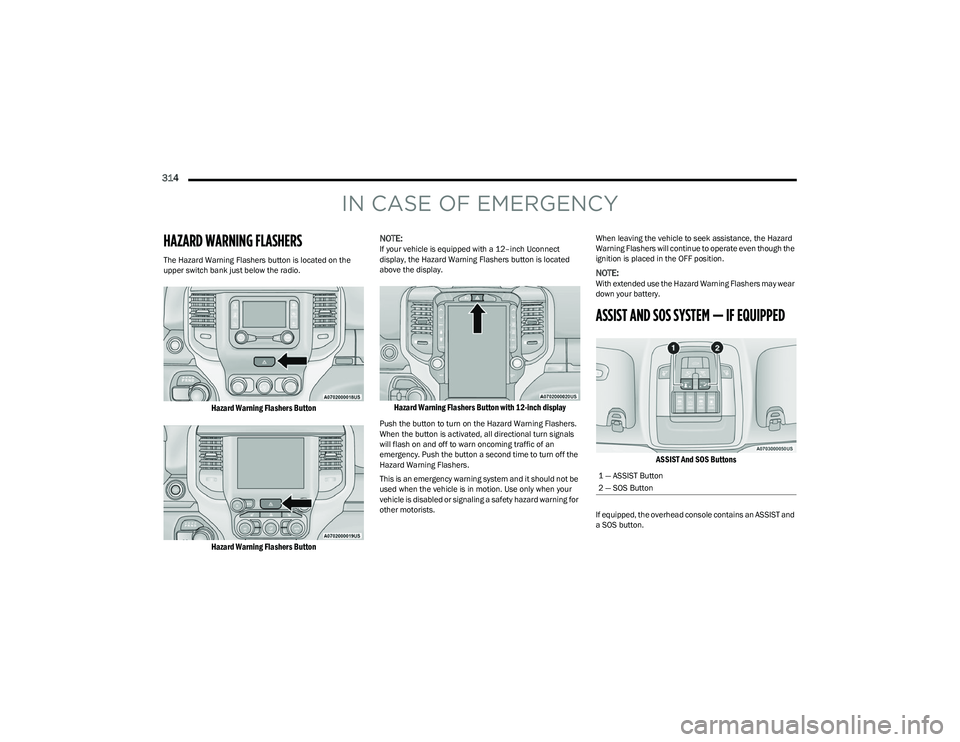
The Hazard Warning Flashers button is located on the
upper switch bank just below the radio.
Hazard Warning Flashers Button
Hazard Warning Flashers Button
NOTE:
If your vehicle is equipped with a 12–inch Uconnect
display, the Hazard Warning Flashers button is located
above the display.
Hazard Warning Flashers Button with 12-inch display
Push the button to turn on the Hazard Warning Flashers.
When the button is activated, all directional turn signals
will flash on and off to warn oncoming traffic of an
emergency. Push the button a second time to turn off the
Hazard Warning Flashers.
This is an emergency warning system and it should not be
used when the vehicle is in motion. Use only when your
vehicle is disabled or signaling a safety hazard warning for
other motorists.
When leaving the vehicle to seek assistance, the Hazard
Warning Flashers will continue to operate even though the
ignition is placed in the OFF position.
NOTE:With extended use the Hazard Warning Flashers may wear
down your battery.
ASSIST AND SOS SYSTEM — IF EQUIPPED
ASSIST And SOS Buttons
If equipped, the overhead console contains an ASSIST and
a SOS button.
1 — ASSIST Button
2 — SOS Button
23_DT_OM_EN_USC_t.book Page 314
Page 318 of 416

316IN CASE OF EMERGENCY
(Continued)
SOS Call System Limitations
Vehicles sold in Mexico
DO NOT have SOS Call system
capabilities.
SOS or other emergency line operators in Mexico may not
answer or respond to SOS system calls.
If the SOS Call system detects a malfunction, any of the
following may occur at the time the malfunction is
detected, and at the beginning of each ignition cycle:
The overhead console lights located within the ASSIST
and SOS buttons will continuously illuminate red.
The Device Screen will display the following message:
“Vehicle device requires service. Please contact an
authorized dealer.”
Where applicable, an In-Vehicle Audio message will
state “Vehicle device requires service. Please contact
an authorized dealer.” Even if the SOS Call system is fully functional, factors
beyond FCA US LLC’s control may prevent or stop the SOS
Call system operation. These include, but are not limited
to, the following factors:
The ignition is in the OFF position
The vehicle’s electrical systems are not intact
The SOS Call system software and/or hardware are
damaged during a crash
The vehicle battery loses power or becomes
disconnected during a vehicle crash
LTE (voice/data) or 4G (data) network and/or Global
Positioning Satellite signals are unavailable or
obstructed
Equipment malfunction at the SOS operator facility
Operator error by the SOS operator
LTE (voice/data) or 4G (data) network congestion
Weather
Buildings, structures, geographic terrain, or tunnels
WARNING!
If anyone in the vehicle could be in danger (e.g., fire
or smoke is visible, dangerous road conditions or
location), do not wait for voice contact from an Emer -
gency Services Agent. All occupants should exit the
vehicle immediately and move to a safe location.
Never place anything on or near the vehicle’s oper -
able network and GPS antennas. You could prevent
operable network and GPS signal reception, which
can prevent your vehicle from placing an emergency
call. An operable network and GPS signal reception is
required for the SOS Call system to function properly.
The SOS Call system is embedded into the vehicle’s
electrical system. Do not add aftermarket electrical
equipment to the vehicle’s electrical system. This
may prevent your vehicle from sending a signal to
initiate an emergency call. To avoid interference that
can cause the SOS Call system to fail, never add
aftermarket equipment (e.g., two-way mobile radio,
CB radio, data recorder, etc.) to your vehicle’s elec -
trical system or modify the antennas on your vehicle.
IF YOUR VEHICLE LOSES BATTERY POWER FOR ANY
REASON (INCLUDING DURING OR AFTER AN ACCI -
DENT), THE UCONNECT FEATURES, APPS AND
SERVICES, AMONG OTHERS, WILL NOT OPERATE.
Modifications to any part of the SOS Call system
could cause the air bag system to fail when you need
it. You could be injured if the air bag system is not
there to help protect you.
WARNING!
Ignoring the overhead console light could mean you
will not have SOS Call services. If the overhead
console light is illuminated and no SOS call placed,
have an authorized dealer service the SOS Call
system immediately.
The Occupant Restraint Control module turns on the
air bag Warning Light on the instrument panel if a
malfunction in any part of the system is detected.
If the Air Bag Warning Light is illuminated, have an
authorized dealer service the Occupant Restraint
Control system immediately.
WARNING!
23_DT_OM_EN_USC_t.book Page 316
Page 335 of 416

333
SERVICING AND MAINTENANCE
SCHEDULED SERVICING
Your vehicle is equipped with an automatic oil change
indicator system. The oil change indicator system will
remind you that it is time to take your vehicle in for
scheduled maintenance.
Based on engine operation conditions, the oil change
indicator message will illuminate. This means that service
is required for your vehicle. Operating conditions such as
frequent short-trips, trailer tow, and extremely hot or cold
ambient temperatures will influence when the “Oil Change
Required” message is displayed. Have your vehicle
serviced as soon as possible, within the next 500 miles
(805 km).An authorized dealer will reset the oil change indicator
message after completing the scheduled oil change. If a
scheduled oil change is performed by someone other than
an authorized dealer, the message can be reset by
referring to the steps described under Instrument Cluster
Display
Úpage 98.
NOTE:Under no circumstances should oil change intervals
exceed 10,000 miles (16,000 km), 12 months or
350 hours of engine run time, whichever comes first.
The 350 hours of engine run or idle time is generally only
a concern for fleet customers.
Once A Month Or Before A Long Trip:
Check engine oil level.
Check windshield washer fluid level.
Check tire pressure and look for unusual wear or
damage. Rotate tires at the first sign of irregular
wear, even if it occurs before the oil indicator system
turns on.
Check the fluid levels of the coolant reservoir, brake
master cylinder, and fill as needed.
Check function of all interior and exterior lights.
8
23_DT_OM_EN_USC_t.book Page 333
Page 408 of 416

406 H
Hazard Driving Through Flowing, Rising, OrShallow Standing Water .................................... 189
Hazard Warning Flashers ............................................ 314
Head Restraints .............................................................. 34
Head Rests ...................................................................... 34
Head Up Display (HUD) — If Equipped
b
................. 105
Headlights .................................................................... 366 Cleaning................................................................... 388
Delay ...........................................................................48
High Beam..................................................................47
High Beam/Low Beam Select Switch .......................47
Lights On Reminder ...................................................48
On With Wipers ..........................................................48
Passing ....................................................................... 48
Switch .........................................................................46
Heads Up Display (HUD) ..................................... 104
, 105
Heated Mirrors ................................................................42 Heated Seats...................................................................33
Heated Steering Wheel...................................................28Heater, Engine Block ................................................... 121
High Beam/Low Beam Select (Dimmer) Switch ...........47
Hill Start Assist ............................................................. 266
Hitches Trailer Towing .......................................................... 176
HomeLink (Garage Door Opener) ..................................42
Hood Release ..................................................................74
HUD ...................................................................... 104
, 105
IIgnition............................................................................. 20 Switch......................................................................... 20
Ignition Park Interlock ..................................................125
Illuminated Entry............................................................. 52
Inside Rearview Mirror ..........................................38
, 314
Instrument Cluster ............................................ 93, 95, 98
Descriptions ........................................................ 94, 96
Display........................................................................ 98
Engine Oil Reset ...................................................... 101
Location And Controls ............................................... 98
Menu Items .............................................................. 101
Instrument Cluster Display Audio ........................................................................ 103
Driver Assist ............................................................. 101
Fuel Economy .......................................................... 102
Off-Road ...................................................................102Speedometer ...........................................................101StopStart .................................................................. 103
Stored Messages..................................................... 103Trailer Tow................................................................ 103
Trip............................................................................103
Vehicle Info .............................................................. 102
Instrument Panel Lens Cleaning ................................. 391
Integrated Trailer Brake Control ..................................180
Interior Appearance Care ............................................. 390
Interior Lights .................................................................. 50
Introduction...................................................................237
Inverter Outlet (115V) .................................................... 67
JJack Location ................................................................ 317
Jacking And Tire Changing
b
.................................... 317
Jump Starting ............................................................... 325
KKey Fob ........................................................................... 16 Panic Alarm ............................................................... 17
Programming Additional Key Fobs ........................... 19
Key Fob Battery Replacement ....................................... 17
Key Fob Programming (Remote Keyless Entry)............ 19 Keyless Enter ‘n Go ............................................... 25
, 118
Passive Entry ............................................................. 25
Keys ................................................................................. 16
LLane Change Assist ........................................................ 49 LaneSense .................................................................... 161
Lap/Shoulder Belts ...................................................... 283
Latches ......................................................................... 313 Hood........................................................................... 74
Lead Free Gasoline ...................................................... 393
Leaks, Fluid................................................................... 313
Life Of Tires ................................................................... 379
Light Air Suspension ........................................................ 113
Light Bulbs ...........................................................313
, 365
23_DT_OM_EN_USC_t.book Page 406
Page 413 of 416

411
Replacement ........................................................... 380
Rotation ................................................................... 386
Run Flat ................................................................... 378
Safety.............................................................. 370
, 377
Sizes ........................................................................ 371
Snow Tires ............................................................... 381 Spare Tires ..................................................... 381
, 382
Spinning .................................................................. 379
Trailer Towing .......................................................... 179
Tread Wear Indicators ............................................ 379
Types ....................................................................... 380 Wheel Nut Torque ................................................... 392
To Open Hood..................................................................74
Tongue Weight/Trailer Weight ........................... 173
, 176
Tonneau Cover ...................................................... 86, 388
Tonneau Cover Cleaning ............................................. 388
Tow/Haul Mode............................................................ 130
Towing .................................................................. 173
, 330
Disabled Vehicle ..................................................... 330
Guide ....................................................................... 176 Recreational ............................................................ 186
Weight...................................................................... 176
Towing Behind A Motorhome ...................................... 186
Traction ......................................................................... 189
Traction Control............................................................ 268 Trailer Reverse Steering Control..................................177
Trailer Sway Control (TSC) .................................. 173
, 268
Trailer Tire Pressure ..................................................... 280
Trailer Towing ................................................................ 173 Frontal Area ............................................................. 173
Hitches .....................................................................176
Minimum Requirements ......................................... 179
Mirrors ........................................................................ 42
Tips ...........................................................................184 Trailer And Tongue Weight...................................... 176Weight Carrying Hitch.............................................. 173Weight Distributing Hitch ........................................ 174
Wiring ....................................................................... 182
Trailer Towing Guide ..................................................... 176
Trailer Weight ................................................................ 176
Transfer Case ................................................................ 354 Electronically Shifted..................................... 130
, 132
Fluid.......................................................................... 397
Transmission................................................................. 125 Automatic ....................................................... 125
, 353
Fluid.......................................................................... 397 Maintenance............................................................353Shifting .....................................................................124
Transporting Pets ......................................................... 311
Tread Wear Indicators ..................................................379
Tri-Fold Tonneau Cover .................................................. 86 Cleaning ..................................................................... 92
Install.......................................................................... 90
Removal ..................................................................... 87
Turn Signals ........................................ 49
, 115, 366, 368
UUconnect Phone Call Features................................................ 232Things You Should Know About Your Uconnect Phone................................................. 235
Uconnect Settings ................................................... 191
Uconnect (Radio) .......................................................... 191
Uconnect 4C Nav With 12-Inch Display ...................... 191
Uconnect 4C/4C Nav With 8.4-Inch Display............... 191
Uconnect Phone ..................................................229
, 230
Answer Or Ignore An Incoming Call — Call Currently In Progress .................................. 233
Answer Or Ignore An Incoming Call — No Call Currently In Progress ............................ 233
Bluetooth Communication Link.............................. 236
Call Continuation..................................................... 234
Call Controls ............................................................ 233
Call Termination ...................................................... 234
Cancel Command.................................................... 230
Connecting To A Particular Mobile Phone Or Audio Device After Pairing ............................ 231
Help Command ....................................................... 230 Join Calls.................................................................. 234
Making A Phone Or Audio Device A Favorite ......... 231
Making A Second Call While Current Call Is In Progress ......................................................... 234
Managing Your Favorites ........................................ 232 Natural Speech ....................................................... 229Operation ................................................................. 229
11
23_DT_OM_EN_USC_t.book Page 411