inflation pressure RAM 1500 2023 Owners Manual
[x] Cancel search | Manufacturer: RAM, Model Year: 2023, Model line: 1500, Model: RAM 1500 2023Pages: 416, PDF Size: 20.59 MB
Page 7 of 416
5
VEHICLE LOADING .......................................................... 172Gross Vehicle Weight Rating (GVWR) ..................... 172
Payload ...................................................................... 172
Gross Axle Weight Rating (GAWR)............................ 172
Tire Size ..................................................................... 172Rim Size ..................................................................... 172Inflation Pressure ...................................................... 172Curb Weight ............................................................... 172
Loading ...................................................................... 172
TRAILER TOWING ............................................................ 173 Common Towing Definitions .................................... 173
Trailer Hitch Type and Maximum Trailer Weight ..... 176Trailer Towing Weights
(Maximum Trailer Weight Ratings) .......................... 176Trailer And Tongue Weight ...................................... 176
Trailer Reverse Steering
Control — If Equipped................................................ 177Towing Requirements .............................................. 179
Towing Tips ............................................................... 184
SNOWPLOW ..................................................................... 184 Before Plowing .......................................................... 185
Snowplow Prep Package Model Availability ............ 185Over The Road Operation With Snowplow
Attached .................................................................... 185Operating Tips ........................................................... 185
General Maintenance ............................................... 185
RECREATIONAL TOWING (BEHIND MOTORHOME) .... 186 Towing This Vehicle Behind Another Vehicle .......... 186
Recreational Towing — Two-Wheel Drive Models ... 186
Recreational Towing — Four-Wheel Drive Models... 187 DRIVING TIPS ................................................................... 189
Driving On Slippery Surfaces .................................. 189
Driving Through Water ............................................. 189
Off-Road Driving Tips ............................................... 190
MULTIMEDIA
UCONNECT SYSTEMS ..................................................... 191
CYBERSECURITY ............................................................. 191
UCONNECT SETTINGS .................................................... 191 Customer Programmable Features ........................ 192
UCONNECT INTRODUCTION............................................ 215 System Overview....................................................... 215
Safety And General Information ............................. 217
UCONNECT MODES ......................................................... 218 Steering Wheel Audio Controls ............................... 218
Radio Mode .............................................................. 218
Media Mode ............................................................. 226
Phone Mode ............................................................. 228
CONNECTED VEHICLE SERVICES —
IF EQUIPPED .................................................................... 236 Is My Vehicle Connected? ........................................ 236
Introduction To Connected Vehicle Services ......... 237
Getting Started With Connected Vehicle
Services .................................................................... 238
Using SiriusXM Guardian™ ..................................... 239
Manage My SiriusXM Guardian™ Account ............. 248
CONNECTED SERVICES FAQS ....................................... 248 Connected Services SOS FAQs — If Equipped ....... 248Connected Services Remote Door
Lock/Unlock FAQs ................................................... 249 Connected Services Roadside Assistance FAQs .... 249
Connected Services Send & Go FAQs —
If Equipped ................................................................ 249
Connected Services Vehicle Finder FAQs ............... 249
Connected Services Stolen Vehicle
Assistance FAQs — If Equipped ............................... 250Connected Services Remote Vehicle
Start FAQs ................................................................. 250
Connected Services Remote Horn & Lights
FAQs ........................................................................... 250Connected Services Account FAQs —
If Equipped................................................................. 251
Data Collection & Privacy.......................................... 252
RADIO OPERATION AND MOBILE PHONES .................252 Regulatory And Safety Information .......................... 253
PERFORMANCE PAGES — IF EQUIPPED .......................253 Timers ........................................................................ 253
Gauges ....................................................................... 254
G-Force ....................................................................... 254
Dynamometer (Dyno)/Engine ................................... 255
Vehicle Dynamics ...................................................... 255
OFF-ROAD PAGES — IF EQUIPPED ................................256 Off-Road Pages Status Bar ...................................... 257Vehicle Dynamics ..................................................... 258Accessory Gauge ....................................................... 259
Pitch & Roll ................................................................ 260
Suspension — If Equipped ........................................ 261Forward Facing Camera — If Equipped .................... 261
23_DT_OM_EN_USC_t.book Page 5
Page 114 of 416
112GETTING TO KNOW YOUR INSTRUMENT PANEL
Rear Axle Locker Fault Warning Light —
If Equipped
This warning light will illuminate to indicate
when a rear axle locker fault has been
detected.
Service Forward Collision Warning (FCW)
Light — If Equipped
This warning light will illuminate to indicate a
fault in the FCW System. Contact an authorized
dealer for service
Úpage 274.
Service Stop/Start System Warning Light —
If Equipped
This warning light will illuminate when the
Stop/Start system is not functioning properly
and service is required. Contact an authorized
dealer for service.
Service 4WD Warning Light — If Equipped
This warning light will illuminate to signal a fault
with the 4WD system. If the light stays on or
comes on during driving, it means that the 4WD
system is not functioning properly and that
service is required. We recommend you drive to the
nearest service center and have the vehicle serviced
immediately.
Cruise Control Fault Warning Light
This warning light will illuminate to indicate the
Cruise Control System is not functioning
properly and service is required. Contact an
authorized dealer.
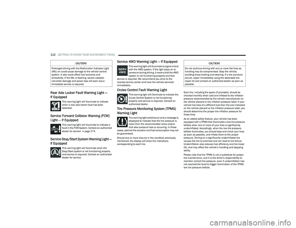
Tire Pressure Monitoring System (TPMS)
Warning Light
The warning light switches on and a message is
displayed to indicate that the tire pressure is
lower than the recommended value and/or
that slow pressure loss is occurring. In these
cases, optimal tire duration and fuel consumption may not
be guaranteed.
Should one or more tires be in the condition previously
mentioned, the display will show the indications
corresponding to each tire. Each tire, including the spare (if provided), should be
checked monthly when cold and inflated to the inflation
pressure recommended by the vehicle manufacturer on
the vehicle placard or tire inflation pressure label. If your
vehicle has tires of a different size than the size indicated
on the vehicle placard or tire inflation pressure label, you
should determine the proper tire inflation pressure for
those tires.
As an added safety feature, your vehicle has been
equipped with a TPMS that illuminates a low tire pressure
telltale when one or more of your tires is significantly
underinflated. Accordingly, when the low tire pressure
telltale illuminates, you should stop and check your tires
as soon as possible, and inflate them to the proper
pressure. Driving on a significantly underinflated tire
causes the tire to overheat and can lead to tire failure.
Underinflation also reduces fuel efficiency and tire tread
life, and may affect the vehicle’s handling and stopping
ability.
Please note that the TPMS is not a substitute for proper
tire maintenance, and it is the driver’s responsibility to
maintain correct tire pressure, even if underinflation has
not reached the level to trigger illumination of the TPMS
low tire pressure telltale.
CAUTION!
Prolonged driving with the Malfunction Indicator Light
(MIL) on could cause damage to the vehicle control
system. It also could affect fuel economy and
driveability. If the MIL is flashing, severe catalytic
converter damage and power loss will soon occur.
Immediate service is required.
CAUTION!
Do not continue driving with one or more flat tires as
handling may be compromised. Stop the vehicle,
avoiding sharp braking and steering. If a tire puncture
occurs, repair immediately using the dedicated tire
repair kit and contact an authorized dealer as soon as
possible.
23_DT_OM_EN_USC_t.book Page 112
Page 174 of 416
172STARTING AND OPERATING
VEHICLE LOADING
GROSS VEHICLE WEIGHT RATING
(GVWR)
The GVWR is the total permissible weight of your vehicle
including driver, passengers, vehicle, options and cargo.
The label also specifies maximum capacities of front and
rear Gross Axle Weight Rating (GAWR). Total load must be
limited so GVWR and front and rear GAWR are not
exceeded.
PAYLOAD
The payload of a vehicle is defined as the allowable load
weight a truck can carry, including the weight of the driver,
all passengers, options and cargo.
GROSS AXLE WEIGHT RATING (GAWR)
The GAWR is the maximum permissible load on the front
and rear axles. The load must be distributed in the cargo
area so that the GAWR of each axle is not exceeded.
Each axle GAWR is determined by the components in the
system with the lowest load carrying capacity (axle,
springs, tires or wheels). Heavier axles, or suspension
components sometimes specified by purchasers for
increased durability, do not necessarily increase the
vehicle's GVWR.
TIRE SIZE
The tire size on the Vehicle Certification Label represents
the actual tire size on your vehicle. Replacement tires
must be equal to the load capacity of this tire size.
RIM SIZE
This is the rim size that is appropriate for the tire size
listed.
INFLATION PRESSURE
This is the cold tire inflation pressure for your vehicle for
all loading conditions up to full Gross Axle Weight Rating
(GAWR).
CURB WEIGHT
The curb weight of a vehicle is defined as the total weight
of the vehicle with all fluids, including vehicle fuel, at full
capacity conditions, and with no occupants or cargo
loaded into the vehicle. The front and rear curb weight
values are determined by weighing your vehicle on a
commercial scale before any occupants or cargo are
added.
LOADING
The actual total weight and the weight of the front and rear
of your vehicle at the ground can best be determined by
weighing it when it is loaded and ready for operation. The entire vehicle should first be weighed on a commercial
scale to ensure that the Gross Vehicle Weight Rating
(GVWR) has not been exceeded. The weight on the front
and rear of the vehicle should then be determined
separately to be sure that the load is properly distributed
over the front and rear axle. Weighing the vehicle may
show that the Gross Axle Weight Rating (GAWR) of either
the front or rear axles has been exceeded but the total
load is within the specified GVWR. If so, weight must be
shifted from front to rear or rear to front as appropriate
until the specified weight limitations are met. Store the
heavier items down low and be sure that the weight is
distributed equally. Stow all loose items securely before
driving.
Improper weight distributions can have an adverse effect
on the way your vehicle steers and handles and the way
the brakes operate.
WARNING!
Do not load your vehicle any heavier than the GVWR or
the maximum front and rear GAWR. If you do, parts on
your vehicle can break, or it can change the way your
vehicle handles. This could cause you to lose control.
Overloading can shorten the life of your vehicle.
23_DT_OM_EN_USC_t.book Page 172
Page 181 of 416

STARTING AND OPERATING179
(Continued)
Some trailers (such as boat trailers) will need to
recalibrate while loaded and unloaded.
NOTE:
The system may not detect a trailer in low light condi -
tions. In sunny conditions, the performance may be
degraded as shadows pass over the trailer.
The driver is always responsible for safe operation of
truck and trailer.
The driver is always in control of the truck as well as the
trailer and is responsible for controlling the throttle and
brakes.
The system may not function when the camera lens is
blocked, blurred (covered with water, snow, ice, dirt,
etc) and will not work unless the tailgate is upright and
fully latched.
TOWING REQUIREMENTS
To promote proper break-in of your new vehicle drivetrain
components, the following guidelines are recommended. Perform the maintenance listed in the Scheduled
Servicing section for the proper maintenance intervals
Úpage 333. When towing a trailer, never exceed the
GAWR or GCWR ratings.
Towing Requirements — Tires
Do not attempt to tow a trailer while using a compact
spare tire.
Do not drive more than 50 mph (80 km/h) when towing
while using a full size spare tire.
Proper tire inflation pressures are essential to the safe
and satisfactory operation of your vehicle.
Check the trailer tires for proper tire inflation pressures
before trailer usage.
Check for signs of tire wear or visible tire damage
before towing a trailer.
Replacing tires with a higher load carrying capacity will
not increase the vehicle's GVWR and GAWR limits.
For further information
Úpage 370.
CAUTION!
Do not tow a trailer at all during the first 500 miles
(805 km) the new vehicle is driven. The engine, axle
or other parts could be damaged.
Then, during the first 500 miles (805 km) that a
trailer is towed, do not drive over 50 mph (80 km/h)
and do not make starts at full throttle. This helps the
engine and other parts of the vehicle wear in at the
heavier loads.
WARNING!
Make certain that the load is secured in the trailer
and will not shift during travel. When trailering cargo
that is not fully secured, dynamic load shifts can
occur that may be difficult for the driver to control.
You could lose control of your vehicle and have a
collision.
When hauling cargo or towing a trailer, do not over -
load your vehicle or trailer. Overloading can cause a
loss of control, poor performance or damage to
brakes, axle, engine, transmission, steering, suspen -
sion, chassis structure or tires.
Safety chains must always be used between your
vehicle and trailer. Always connect the chains to the
hook retainers of the vehicle hitch. Cross the chains
under the trailer tongue and allow enough slack for
turning corners.
Vehicles with trailers should not be parked on a
grade. When parking, apply the parking brake on the
tow vehicle. Put the tow vehicle transmission in
PARK. For four-wheel drive vehicles, make sure the
transfer case is not in NEUTRAL. Always, block or
"chock" the trailer wheels.
GCWR must not be exceeded.
Total weight must be distributed between the tow
vehicle and the trailer such that the following four
ratings are not exceeded :
GVWR
GTW
GAWR
Tongue weight rating for the trailer hitch utilized
WARNING!
4
23_DT_OM_EN_USC_t.book Page 179
Page 279 of 416

SAFETY277
TIRE PRESSURE MONITORING SYSTEM
(TPMS)
TPMS will warn the driver of a low tire pressure based on
the vehicle recommended cold placard pressure.
NOTE:The TPMS Warning Light will illuminate in the instrument
cluster and a chime will sound when tire pressure is low in
one or more of the four active road tires. In addition, the
instrument cluster will display a graphic showing the
pressure values of each tire with the low tire pressure
values in a different color, or the Uconnect radio will
display a TPMS message; when this occurs you must
increase the tire pressure to the recommended cold
placard pressure in order for the TPMS Warning Light to
turn off.
The tire pressure will vary with temperature by about 1 psi
(7 kPa) for every 12°F (6.5°C). This means that when the
outside temperature decreases, the tire pressure will
decrease. Tire pressure should always be set based on
cold inflation tire pressure. This is defined as the tire
pressure after the vehicle has not been driven for at least
three hours, or driven less than 1 mile (1.6 km) after a
three hour period. The cold tire inflation pressure must not
exceed the maximum inflation pressure molded into the
tire sidewall. The tire pressure will also increase as the
vehicle is driven — this is normal and there should be no
adjustment for this increased pressure.
See
Úpage 370 on how to properly inflate the vehicle’s
tires. The TPMS will warn the driver of a low tire pressure if the
tire pressure falls below the low-pressure warning limit for
any reason, including low temperature effects and natural
pressure loss through the tire
Úpage 402.
The TPMS will continue to warn the driver of low tire
pressure as long as the condition exists, and will not turn
off until the tire pressure is at or above the recommended
cold placard pressure. Once the low TPMS Warning Light
illuminates, increase the tire pressure to the
recommended cold placard pressure in order for the
TPMS Warning Light to turn off. The system will
automatically update and the TPMS Warning Light will turn
off once the system receives the updated tire pressures.
The vehicle may need to be driven for up to 20 minutes
above 15 mph (24 km/h) in order for the TPMS to receive
this information.
NOTE:When filling warm tires, the tire pressure may need to be
increased up to an additional 4 psi (28 kPa) above the
recommended cold placard pressure in order to turn the
TPMS Warning Light off.
For example, your vehicle may have a recommended cold
(parked for more than three hours) placard pressure of
30 psi (207 kPa). If the ambient temperature is 68°F
(20°C) and the measured tire pressure is 27 psi
(186 kPa), a temperature drop to 20°F (-7°C) will
decrease the tire pressure to approximately 23 psi
(158 kPa). This tire pressure is sufficiently low enough
to turn on the TPMS Warning Light. Driving the vehicle may cause the tire pressure to rise to
approximately 27 psi (186 kPa), but the TPMS Warning
Light will still be on. In this situation, the TPMS Warning
Light will turn off only after the tires are inflated to the
vehicle’s recommended cold placard pressure value.
CAUTION!
The TPMS has been optimized for the original equip -
ment tires and wheels. TPMS pressures and warning
have been established for the tire size equipped on
your vehicle. Undesirable system operation or sensor
damage may result when using replacement equip -
ment that is not of the same size, type, and/or style.
Aftermarket wheels can cause sensor damage.
Using aftermarket tire sealants may cause the Tire
Pressure Monitoring System (TPMS) sensor to
become inoperable. After using an aftermarket tire
sealant it is recommended that you take your vehicle
to an authorized dealership to have your sensor func -
tion checked.
After inspecting or adjusting the tire pressure always
reinstall the valve stem cap. This will prevent mois -
ture and dirt from entering the valve stem, which
could damage the TPMS sensor.
6
23_DT_OM_EN_USC_t.book Page 277
Page 280 of 416

278SAFETY
NOTE:
The TPMS is not intended to replace normal tire care
and maintenance or to provide warning of a tire failure
or condition.
The TPMS should not be used as a tire pressure gauge
while adjusting your tire pressure, unless your vehicle
is equipped with a Tire Fill Alert (TFA) system.
Driving on a significantly underinflated tire causes the
tire to overheat and can lead to tire failure. Underinfla -
tion also reduces fuel efficiency and tire tread life, and
may affect the vehicle’s handling and stopping ability.
The TPMS is not a substitute for proper tire mainte -
nance, and it is the driver’s responsibility to maintain
correct tire pressure using an accurate tire pressure
gauge, even if underinflation has not reached the level
to trigger illumination of the TPMS Warning Light.
Seasonal temperature changes will affect tire pres -
sure, and the TPMS will monitor the actual tire pres -
sure in the tire.
Tire Pressure Monitoring System Display
The Tire Pressure Monitoring System (TPMS) uses wireless
technology with wheel rim mounted electronic sensors to
monitor tire pressure levels. Sensors, mounted to each
wheel as part of the valve stem, transmit tire pressure
readings to the receiver module.
NOTE:It is particularly important for you to check the tire
pressure in all of the tires on your vehicle monthly and to
maintain the proper pressure.
The TPMS consists of the following components:
Receiver module
Four Tire Pressure Monitoring System sensors
Various Tire Pressure Monitoring System messages,
which display in the instrument cluster
Tire Pressure Monitoring System Warning Light
Tire Pressure Monitoring System Low
Pressure Warnings
The Tire Pressure Monitoring System (TPMS)
Warning Light will illuminate in the instrument
cluster and a chime will sound when tire
pressure is low in one or more of the four active
road tires. In addition, the instrument cluster will display a
graphic showing the pressure values of each tire with the
low tire pressure values in a different color. An "Inflate to
XX" message will also be displayed.
Low Tire Pressure Display
Should this occur, you should stop as soon as possible
and inflate the tires with a low pressure condition
(those in a different color in the instrument cluster
graphic) to the vehicle’s recommended cold placard
pressure inflation value as shown in the "Inflate to XX"
message. Once the system receives the updated tire
pressures, the system will automatically update, the
graphic display in the instrument cluster will return to its
original color, and the Tire Pressure Monitoring System
Warning Light will turn off. The vehicle may need to be
driven for up to 20 minutes above 15 mph (24 km/h) in
order for the TPMS to receive this information.
NOTE:When filling warm tires, the tire pressure may need to be
increased up to an additional 4 psi (28 kPa) above the
recommended cold placard pressure in order to turn the
Tire Pressure Monitoring System Warning Light off.
23_DT_OM_EN_USC_t.book Page 278
Page 282 of 416

280SAFETY
The system will be activated when a positive increase in
tire pressure is detected by the TPMS while inflating the
tire. The ignition must be in the RUN mode, with the
transmission in PARK.
NOTE:It is not required to have the engine running to enter Tire
Fill Alert mode.
The hazard lamps will come on to confirm the vehicle is in
Tire Fill Alert mode.
When Tire Fill Alert mode is entered, the tire pressure
display screen will be displayed in the instrument cluster.
If the hazard lamps do not come on while inflating the tire,
the TPMS sensor may be out of range preventing the TPMS
sensor signal from being received. In this case, the vehicle
may need to be moved either forward or backward slightly
to exit the null spot.
Operation:
The horn will sound once to let the user know when to
stop filling the tire, when it reaches recommended
pressure.
The horn will sound three times if the tire is overfilled
and will continue to sound every five seconds if the
user continues to inflate the tire.
The horn will sound once again when enough air is let
out to reach proper inflation level.
The horn will also sound three times if the tire is then
underinflated and will continue to sound every five
seconds if the user continues to deflate the tire.
Trailer Tire Pressure Monitoring System
(TTPMS) — If Equipped
The Trailer Tire Pressure Monitoring System (TTPMS) is a
feature that displays the trailer tire pressure values and
warns the driver of a low tire pressure event based on the
driver’s set target tire pressure value, through TTPMS
settings found in the radio.
The TTPMS monitors the pressure of each tire and warns
the driver through the instrument cluster, when either a
low tire pressure condition falls below 25% of the driver’s
set pressure or if a system malfunction occurs. The
instrument cluster will display the actual tire pressure or
dashes for each of the trailer tires in the correct trailer
position, based on trailer configuration. The TTPMS can
support up to 12 trailer tires per configured trailer on up to
four configurable trailers
Úpage 191.
Trailer Tire Pressure Monitoring System
Trailer Tire Pressure Sensor Pairing
In order use this feature, the provided tire pressure
sensors must be installed in the desired trailer tires and
the sensors must be paired to the truck. If the target trailer
requires more than the provided four sensors, additional
sensors can be purchased at an authorized Ram
dealership.
With the sensors installed and the trailer near or
connected to your Ram truck, initiate the pairing process
by entering the settings menu in the radio and selecting
trailer. Select the desired trailer profile to pair to, open the
“Tire Pressure” menu, and hit “Setup All Tires”
Úpage 191.
NOTE:The vehicle may not be driven until the pairing process is
complete.
Trailer Tire Pressure Settings
23_DT_OM_EN_USC_t.book Page 280
Page 314 of 416

312SAFETY
(Continued)
(Continued)
Floor Mat Safety Information
Always use floor mats designed to fit your vehicle. Only use
a floor mat that does not interfere with the operation of the
accelerator, brake or clutch pedals. Only use a floor mat
that is securely attached using the floor mat fasteners so
it cannot slip out of position and interfere with the
accelerator, brake or clutch pedals or impair safe
operation of your vehicle in other ways.
PERIODIC SAFETY CHECKS YOU SHOULD
M
AKE OUTSIDE THE VEHICLE
Tires
Examine tires for excessive tread wear and uneven wear
patterns. Check for stones, nails, glass, or other objects
lodged in the tread or sidewall. Inspect the tread for cuts
and cracks. Inspect sidewalls for cuts, cracks, and bulges.
Check the lug nut/bolt torque for tightness. Check the
tires (including spare) for proper cold inflation pressure.
WARNING!
An improperly attached, damaged, folded, or stacked
floor mat, or damaged floor mat fasteners may cause
your floor mat to interfere with the accelerator, brake, or
clutch pedals and cause a loss of vehicle control.
To prevent SERIOUS INJURY or DEATH:
ALWAYS securely attach your floor mat
using the floor mat fasteners. DO NOT
install your floor mat upside down or turn
your floor mat over. Lightly pull to confirm
mat is secured using the floor mat fasteners on a
regular basis.
ALWAYS REMOVE THE EXISTING FLOOR
MAT FROM THE VEHICLE before installing
any other floor mat. NEVER install or stack
an additional floor mat on top of an
existing floor mat.
ONLY install floor mats designed to fit your vehicle.
NEVER install a floor mat that cannot be properly
attached and secured to your vehicle. If a floor mat
needs to be replaced, only use a FCA approved floor
mat for the specific make, model, and year of your
vehicle.
ONLY use the driver’s side floor mat on the driver’s
side floor area. To check for interference, with the
vehicle properly parked with the engine off, fully
depress the accelerator, the brake, and the clutch
pedal (if present) to check for interference. If your
floor mat interferes with the operation of any pedal,
or is not secure to the floor, remove the floor mat
from the vehicle and place the floor mat in your
trunk.
ONLY use the passenger’s side floor mat on the
passenger’s side floor area.
ALWAYS make sure objects cannot fall or slide into
the driver’s side floor area when the vehicle is
moving. Objects can become trapped under acceler -
ator, brake, or clutch pedals and could cause a loss
of vehicle control.
NEVER place any objects under the floor mat (e.g.,
towels, keys, etc.). These objects could change the
position of the floor mat and may cause interference
with the accelerator, brake, or clutch pedals.
WARNING!
If the vehicle carpet has been removed and
re-installed, always properly attach carpet to the floor
and check the floor mat fasteners are secure to the
vehicle carpet. Fully depress each pedal to check for
interference with the accelerator, brake, or clutch
pedals then re-install the floor mats.
It is recommended to only use mild soap and water
to clean your floor mats. After cleaning, always check
your floor mat has been properly installed and is
secured to your vehicle using the floor mat fasteners
by lightly pulling mat.
WARNING!
23_DT_OM_EN_USC_t.book Page 312
Page 374 of 416
372SERVICING AND MAINTENANCE
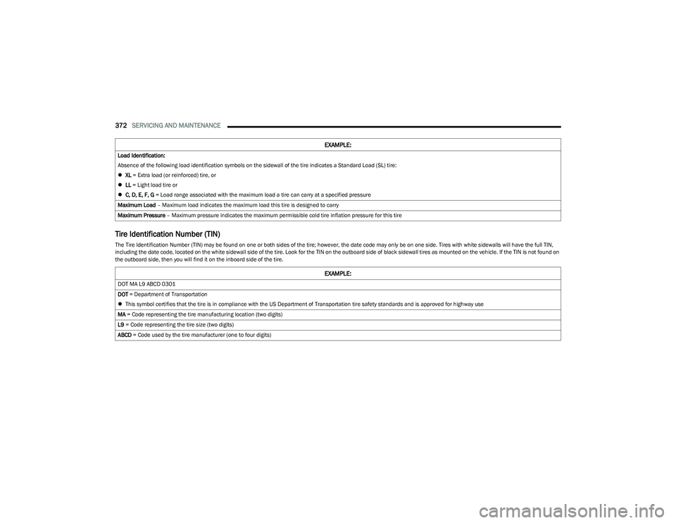
Tire Identification Number (TIN)
The Tire Identification Number (TIN) may be found on one or both sides of the tire; however, the date code may only be on one side. Tires with white sidewalls will have the full TIN,
including the date code, located on the white sidewall side of the tire. Look for the TIN on the outboard side of black sidewall tires as mounted on the vehicle. If the TIN is not found on
the outboard side, then you will find it on the inboard side of the tire.Load Identification:
Absence of the following load identification symbols on the sidewall of the tire indicates a Standard Load (SL) tire:
XL = Extra load (or reinforced) tire, or
LL = Light load tire or
C, D, E, F, G = Load range associated with the maximum load a tire can carry at a specified pressure
Maximum Load – Maximum load indicates the maximum load this tire is designed to carry
Maximum Pressure – Maximum pressure indicates the maximum permissible cold tire inflation pressure for this tire
EXAMPLE:
EXAMPLE:
DOT MA L9 ABCD 0301
DOT = Department of Transportation
This symbol certifies that the tire is in compliance with the US Department of Transportation tire safety standards and is approved for highway use
MA = Code representing the tire manufacturing location (two digits)
L9 = Code representing the tire size (two digits)
ABCD = Code used by the tire manufacturer (one to four digits)
23_DT_OM_EN_USC_t.book Page 372
Page 375 of 416
SERVICING AND MAINTENANCE373
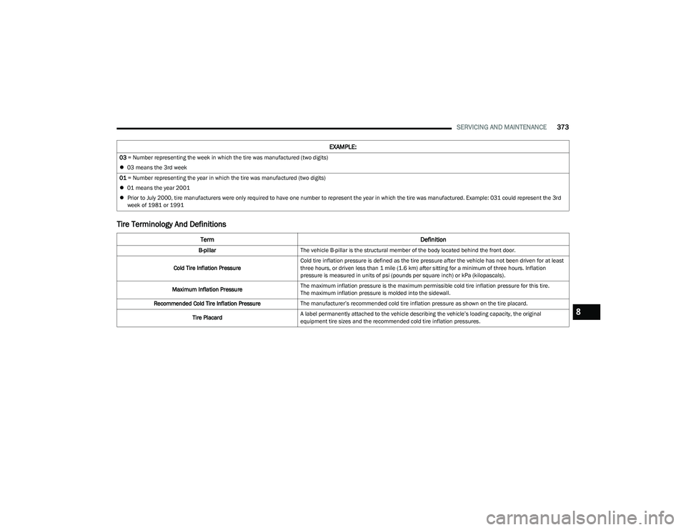
Tire Terminology And Definitions
03 = Number representing the week in which the tire was manufactured (two digits)
03 means the 3rd week
01 = Number representing the year in which the tire was manufactured (two digits)
01 means the year 2001
Prior to July 2000, tire manufacturers were only required to have one number to represent the year in which the tire was manufactured. Example: 031 could represent the 3rd
week of 1981 or 1991
Term Definition
B-pillarThe vehicle B-pillar is the structural member of the body located behind the front door.
Cold Tire Inflation Pressure Cold tire inflation pressure is defined as the tire pressure after the vehicle has not been driven for at least
three hours, or driven less than 1 mile (1.6 km) after sitting for a minimum of three hours. Inflation
pressure is measured in units of psi (pounds per square inch) or kPa (kilopascals).
Maximum Inflation Pressure The maximum inflation pressure is the maximum permissible cold tire inflation pressure for this tire.
The maximum inflation pressure is molded into the sidewall.
Recommended Cold Tire Inflation Pressure The manufacturer’s recommended cold tire inflation pressure as shown on the tire placard.
Tire Placard A label permanently attached to the vehicle describing the vehicle’s loading capacity, the original
equipment tire sizes and the recommended cold tire inflation pressures.
EXAMPLE:
8
23_DT_OM_EN_USC_t.book Page 373