change Ram 2500 2011 Service Manual
[x] Cancel search | Manufacturer: RAM, Model Year: 2011, Model line: 2500, Model: Ram 2500 2011Pages: 622
Page 414 of 622

CAUTION!
After inspecting or adjusting the tire pressure, al-
ways reinstall the valve stem cap. This will prevent
moisture and dirt from entering the valve stem,
which could damage the valve stem.
Inflation pressures specified on the placard are always
“cold tire inflation pressure.” Cold tire inflation pressure
is defined as the tire pressure after the vehicle has not
been driven for at least three hours or driven less than
1 mile (1.6 km) after a three hour period. The cold tire
inflation pressure must not exceed the maximum infla-
tion pressure molded into the tire sidewall.
Check tire pressures more often if subject to a wide range
of outdoor temperatures as tire pressures vary with
temperature changes.Tire pressures change by approximately 1 psi (7 kPa) per
12°F (7°C) of air temperature change. Keep this in mind
when checking tire pressure inside a garage, especially in
the Winter.
Example: If garage temperature = 68°F (20°C) and the
outside temperature = 32°F (0°C) then the cold tire
inflation pressure should be increased by 3 psi (21 kPa),
which equals 1 psi (7 kPa) for every 12°F (7°C) for this
outside temperature condition.
Tire pressure may increase from 2 to 6 psi (13 to 40 kPa)
during operation. Do not reduce this normal pressure
build up or your tire pressure will be too low.
Tire Pressures for High Speed Operation
The manufacturer advocates driving at safe speeds
within posted speed limits. Where speed limits or condi-
tions are such that the vehicle can be driven at high
speeds, maintaining correct tire inflation pressure is very
important. Increased tire pressure and reduced vehicle
5
STARTING AND OPERATING 413
Page 418 of 622
Keep dismounted tires in a cool, dry place with as little
exposure to light as possible. Protect tires from contact
with oil, grease, and gasoline.
Replacement Tires
The tires on your new vehicle provide a balance of many
characteristics. They should be inspected regularly for
wear and correct cold tire inflation pressure. The manu-
facturer strongly recommends that you use tires equiva-
lent to the originals in size, quality and performance
when replacement is needed. (Refer to the paragraph on
“Tread Wear Indicators”). Refer to the “Tire and Loading
Information” placard for the size designation of your tire.
The service description and load identification will be
found on the original equipment tire. Failure to use
equivalent replacement tires may adversely affect the
safety, handling, and ride of your vehicle. We recommend
that you contact your original equipment or an autho-
rized tire dealer with any questions you may have on tire
specifications or capability.
WARNING!
•Do not use a tire, wheel size or rating other than
that specified for your vehicle. Some combinations
of unapproved tires and wheels may change sus-
pension dimensions and performance characteris-
tics, resulting in changes to steering, handling, and
braking of your vehicle. This can cause unpredict-
able handling and stress to steering and suspen-
sion components. You could lose control and have
a collision resulting in serious injury or death. Use
only the tire and wheel sizes with load ratings
approved for your vehicle.
(Continued)
5
STARTING AND OPERATING 417
Page 427 of 622
NOTE:
•The TPMS is not intended to replace normal tire care
and maintenance or to provide warning of a tire failure
or condition.
•The TPMS should not be used as a tire pressure gauge
while adjusting your tire pressure.
•Driving on a significantly under-inflated tire causes
the tire to overheat and can lead to tire failure.
Under-inflation also reduces fuel efficiency and tire
tread life, and may affect the vehicle’s handling and
stopping ability.
•The TPMS is not a substitute for proper tire mainte-
nance, and it is the driver ’s responsibility to maintain
correct tire pressure using an accurate tire pressure
gauge, even if under-inflation has not reached the
level to trigger illumination of the TPM Telltale Light.
•Seasonal temperature changes will affect tire pressure,
and the TPMS will monitor the actual tire pressure in
the tire.
Base System
The Tire Pressure Monitor System (TPMS) uses wireless
technology with wheel rim mounted electronic sensors to
monitor tire pressure levels. Sensors mounted to each
wheel as part of the valve stem transmit tire pressure
readings to the receiver module.
NOTE:It is particularly important for you to check the
tire pressure in all of the tires on your vehicle monthly
and to maintain the proper pressure.
The TPMS consists of the following components:
•Receiver module,
•Four TPM sensors, and
•TPM Telltale Light
426 STARTING AND OPERATING
Page 434 of 622
also equipped to be driven with tire pressures appro-
priate to either a Light Load condition or the vehicle
Max Load condition.
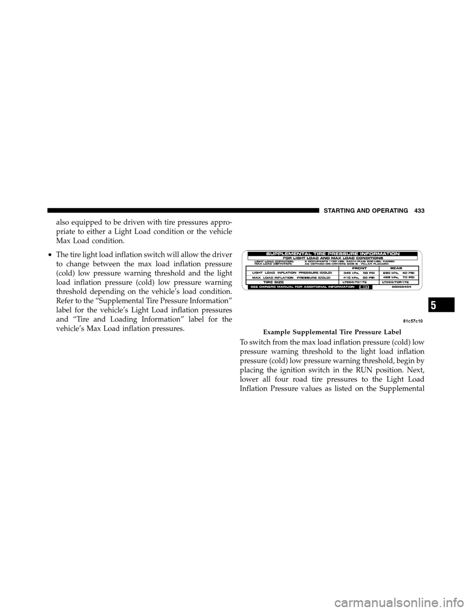
•The tire light load inflation switch will allow the driver
to change between the max load inflation pressure
(cold) low pressure warning threshold and the light
load inflation pressure (cold) low pressure warning
threshold depending on the vehicle’s load condition.
Refer to the “Supplemental Tire Pressure Information”
label for the vehicle’s Light Load inflation pressures
and “Tire and Loading Information” label for the
vehicle’s Max Load inflation pressures.
To switch from the max load inflation pressure (cold) low
pressure warning threshold to the light load inflation
pressure (cold) low pressure warning threshold, begin by
placing the ignition switch in the RUN position. Next,
lower all four road tire pressures to the Light Load
Inflation Pressure values as listed on the Supplemental
Example Supplemental Tire Pressure Label
5
STARTING AND OPERATING 433
Page 435 of 622
Tire Pressure Information label. The Supplemental Tire
Pressure Information label is located on the rear face of
the driver door opening. Use an accurate tire gauge to
check the tire pressures when lowering all four tire
pressures. The vehicle may need to be driven above
15 mph (25 km/h) to receive this updated pressure
information. After all four tire pressures have been
lowered to the Light Load inflation pressures, press the
tire light load inflation switch. If the tire light load
inflation switch’s amber colored LED turns ON, the
TPMS is using the light load inflation pressure (cold) low
pressure warning thresholds.
If the tire light load inflation switch amber colored LED
flashes on and off for 10 seconds, after all four tire
pressures have been lowered to the Light Load inflation
pressures, the pressure in any one of the four tires may
not be at the light load inflation pressure (cold) values as
indicated for the Light Load condition as defined on the
Supplemental Tire Pressure Information label located onthe rear face of the driver door. Using an accurate tire
pressure gauge, re-check the tire pressures for the light
load inflation pressure (cold) value.
WARNING!
It is the driver ’s responsibility to change to the max
load inflation pressure (cold) low pressure warning
threshold condition when not driving in the light
load condition as defined as two occupants (150 lbs
[68 kg] each) plus 200 pounds (91 kg) of cargo. The
vehicle “Light Load Definition” is found in the
Supplemental Tire Pressure Information label lo-
cated on the rear face of the driver door. Failure to do
so may cause you to lose control resulting in a
collision, causing serious or fatal injury.
To switch back to the max load inflation pressure (cold)
low pressure warning threshold, press the tire light load
inflation switch. It is not necessary to first fill the tires to
434 STARTING AND OPERATING
Page 439 of 622
To fix a Non-FFV vehicle inadvertently fueled once with
E-85 perform the following:
•drain the fuel tank (see your authorized dealer)
•change the engine oil and oil filter
•disconnect and reconnect the battery to reset the
engine controller memory
More extensive repairs will be required for prolonged
exposure to E-85 fuel.
MMT In Gasoline
MMT is a manganese containing metallic additive that is
blended into some gasoline to increase octane. Gasoline
blended with MMT provides no performance advantage
beyond gasoline of the same octane number without
MMT. Gasoline blended with MMT reduces spark plug
life and reduces emissions system performance in some
vehicles. The manufacturer recommends that gasoline
without MMT be used in your vehicle. The MMT contentof gasoline may not be indicated on the gasoline pump,
therefore, you should ask your gasoline retailer whether
or not his/her gasoline contains MMT. It is even more
important to look for gasolines without MMT in Canada,
because MMT can be used at levels higher than those
allowed in the United States. MMT is prohibited in
Federal and California reformulated gasoline.
Materials Added To Fuel
All gasoline sold in the United States is required to
contain effective detergent additives. Use of additional
detergents or other additives is not needed under normal
conditions and would result in unnecessary cost. There-
fore, you should not have to add anything to the fuel.
438 STARTING AND OPERATING
Page 449 of 622

then be determined separately to be sure that the load is
properly distributed over the front and rear axle. Weigh-
ing the vehicle may show that the GAWR of either the
front or rear axles has been exceeded but the total load is
within the specified GVWR. If so, weight must be shifted
from front to rear or rear to front as appropriate until the
specified weight limitations are met. Store the heavier
items down low and be sure that the weight is distributed
equally. Stow all loose items securely before driving.
Improper weight distributions can have an adverse effect
on the way your vehicle steers and handles and the way
the brakes operate.CAUTION!
Do not load your vehicle any heavier than the GVWR
or the maximum front and rear GAWR. If you do,
parts on your vehicle can break, or it can change the
way your vehicle handles. This could cause you to
lose control. Also overloading can shorten the life of
your vehicle.
TRAILER TOWING
In this section you will find safety tips and information
on limits to the type of towing you can reasonably do
with your vehicle. Before towing a trailer, carefully
review this information to tow your load as efficiently
and safely as possible.
To maintain warranty coverage, follow the requirements
and recommendations in this manual concerning ve-
hicles used for trailer towing.
448 STARTING AND OPERATING
Page 460 of 622

NOTE:This module has been designed and verified for
electric trailer brakes. To determine the type of brakes on
your trailer, check with your trailer manufacturer or
dealer.The user interface consists of the following:
GAIN/ Brake Output Power Display
Shows the current GAIN setting.
This display may also be used to display diagnostic
information, if needed.
•SC — Short Circuit to Ground
•Sb — Short to Battery
•CF — Controller Fault – If this message appears on the
display, see your authorized dealer.
When the vehicle brakes are applied, the display will no
longer show GAIN and will change to the output to the
trailer brakes.
Manual Brake Control Lever
Slide the manual brake control lever to the right to
activate power to the trailer’s electric brakes independent
of the tow vehicle’s brakes. If the manual brake control
1 — GAIN/Brake Output Power Display
2 — Manual Brake Control Lever
3 — Trailer Brake Status Indicator Light
4 — GAIN Adjustment Buttons
5
STARTING AND OPERATING 459
Page 461 of 622

lever is activated while the brake is also applied, the
greater of the two inputs determines the power sent to
the trailer brakes.
The trailer and the vehicle’s brake lamps will come on
when either vehicle braking or manual trailer brakes are
applied.
Trailer Brake Status Indicator Light
This light indicates the trailer electrical connection status.
If no electrical connection is detected after the ignition is
turned on, pressing the GAIN adjustment button or
sliding the manual brake control lever will display the
GAIN setting for 10 seconds and the “Trailer Brake Status
Indicator Light” will not be displayed.
If a fault is detected in the trailer wiring or the Integrated
Trailer Brake Module (ITBM), the “Trailer Brake Status
Indicator Light” will flash.GAIN Adjustment Buttons (+/-)
Pressing these buttons will adjust the brake control
power output to the trailer brakes in 0.5 increments. The
GAIN setting can be increased to a maximum of 10 or
decreased to a minimum of 0 (no trailer braking).
GAIN
The GAIN setting is used to set the trailer brake control
for the specific towing condition and should be changed
as towing conditions change. Changes to towing condi-
tions include trailer load, vehicle load, road conditions
and weather.
Adjusting GAIN
NOTE:This should only be performed in a traffic free
environment at speeds of approximately 20–25 mph
(30–40 km/h).
460 STARTING AND OPERATING
Page 466 of 622

NOTE:Using “TOW/HAUL” mode or a lower gear
range while operating the vehicle under heavy operating
conditions will improve performance and extend trans-
mission life by reducing excessive shifting and heat build
up. This action will also provide better engine braking.
The automatic transmission fluid and filter should be
changed if you regularly tow a trailer for more than
45 minutes of continuous operation. Refer to “Mainte-
nance Schedule” for the proper maintenance intervals.
NOTE:Check the automatic transmission fluid level
before towing.
Tow/Haul
To reduce potential for automatic transmission overheat-
ing, turn the “TOW/HAUL” feature ON when driving in
hilly areas, or select a lower gear range (using the
Electronic Range Select (ERS) feature) on more severe
grades.
Electronic Speed Control – If Equipped
Do not use in hilly terrain or with heavy loads.
When using the speed control, if you experience speed
drops greater than 10 mph (16 km/h), disengage until
you can get back to cruising speed.
Use speed control in flat terrain and with light loads to
maximize fuel efficiency.
Cooling System
To reduce potential for engine and transmission over-
heating, take the following actions:
City Driving
When stopped for short periods of time, shift the trans-
mission into NEUTRAL and increase engine idle speed.
Highway Driving
Reduce speed.
5
STARTING AND OPERATING 465