Ram 2500 2017 Owner's Manual
Manufacturer: RAM, Model Year: 2017, Model line: 2500, Model: Ram 2500 2017Pages: 734, PDF Size: 7.3 MB
Page 181 of 734
3.Without releasing the button proceed with “Program-
ming A Non-Rolling Code” step 2 and follow all remain-
ing steps.
Canadian/Gate Operator Programming
For programming transmitters in Canada/United States
that require the transmitter signals to “time-out” after
several seconds of transmission.
Canadian radio frequency laws require transmitter signals
to time-out (or quit) after several seconds of transmission –
which may not be long enough for HomeLink to pick up
the signal during programming. Similar to this Canadian
law, some U.S. gate operators are designed to time-out in
the same manner.
It may be helpful to unplug the device during the cycling
process to prevent possible overheating of the garage door
or gate motor.
1. Turn the ignition switch to the ON/RUN position.
For vehicle’s equipped with Keyless Enter-N-Go, place the
ignition in the RUN position with the Engine ON. 2. Place the hand - held transmitter 1 to 3 inches (3 to 8 cm)
away from the HomeLink button you wish to program.
3. Push and hold the HomeLink button while you push and release (“cycle”), your hand - held transmitter every
two seconds.
4. Continue to hold both buttons until the instrument cluster display changes from “CHANNEL # TRAIN-
ING” to “CHANNEL # TRAINED,” then release both
buttons.
NOTE: •It may take up to 30 seconds or longer in some cases
for the channel to train.
• If the instrument cluster display shows “DID NOT
TRAIN”, repeat from Step 2.
5. Push and hold the programmed HomeLink button. The instrument cluster display will display “CHANNEL #
TRANSMIT.” If the device is plugged in and activates,
programming is complete.
If you unplugged the garage door opener/device for
programming, plug it back in at this time.3
UNDERSTANDING THE FEATURES OF YOUR VEHICLE 179
Page 182 of 734
Reprogramming A Single HomeLink Button
(Canadian/Gate Operator)
To reprogram a channel that has been previously trained,
follow these steps:
1. Turn the ignition switch to the ON/RUN position.
For vehicle’s equipped with Keyless Enter-N-Go, place the
ignition in the RUN position with the Engine ON.
2. Push and hold the desired HomeLink button until theinstrument cluster display shows “CHANNEL #
TRAINING” Do not release the button.
3. Without releasing the button proceed with “Canadian/
Gate Operator Programming” Step 2 and follow all
remaining steps.
Using HomeLink
To operate, push and release the programmed HomeLink
button. Activation will now occur for the programmed
device (i.e. garage door opener, gate operator, security
system, entry door lock, home/office lighting, etc.) The
hand-held transmitter of the device may also be used at
any time.
Security
It is advised to erase all channels before you sell or turn in
your vehicle.
To erase the channels press and hold the two outside
HomeLink buttons (I and III) for up 20 seconds. The
instrument cluster display will display “CLEARING
CHANNELS.” Release the buttons when the instrument
cluster display shows “CHANNELS CLEARED.”
The HomeLink Universal Transceiver is disabled when the
Vehicle Security Alarm is active.
Troubleshooting Tips
If you are having trouble programming HomeLink, here
are some of the most common solutions:
• Replace the battery in the Garage Door Opener hand-
held transmitter.
• Push the LEARN button on the Garage Door Opener to
complete the training for a Rolling Code.
• Did you unplug the device for programming and re-
member to plug it back in?
180 UNDERSTANDING THE FEATURES OF YOUR VEHICLE
Page 183 of 734
If you have any problems, or require assistance, please call
toll-free 1-800-355-3515 or, on the Internet at HomeLink.com
for information or assistance.
WARNING!
•Vehicle exhaust contains carbon monoxide, a danger-
ous gas. Do not run your vehicle in the garage while
programming the transceiver. Exhaust gas can cause
serious injury or death.
•
Your motorized door or gate will open and close while
you are programming the universal transceiver. Do not
program the transceiver if people, pets or other objects
are in the path of the door or gate. Only use this
transceiver with a garage door opener that has a “stop
and reverse” feature as required by Federal safety
standards. This includes most garage door opener mod-
els manufactured after 1982. Do not use a garage door
opener without these safety features. Call toll-free
1-800-355-3515 or, on the Internet at HomeLink.com for
safety information or assistance.
General Information
This device complies with FCC rules Part 15 and Industry
Canada RSS-210. Operation is subject to the following two
conditions:
1. This device may not cause harmful interference, and
2.
This device must accept any interference received, includ-
ing interference that may cause undesired operation.
NOTE:
• The transmitter has been tested and it complies with
FCC and IC rules. Changes or modifications not ex-
pressly approved by the party responsible for compli-
ance could void the user ’s authority to operate the
device.
• The term IC before the certification/registration number
only signifies that Industry Canada technical specifica-
tions were met.
3
UNDERSTANDING THE FEATURES OF YOUR VEHICLE 181
Page 184 of 734
POWER SUNROOF — IF EQUIPPED
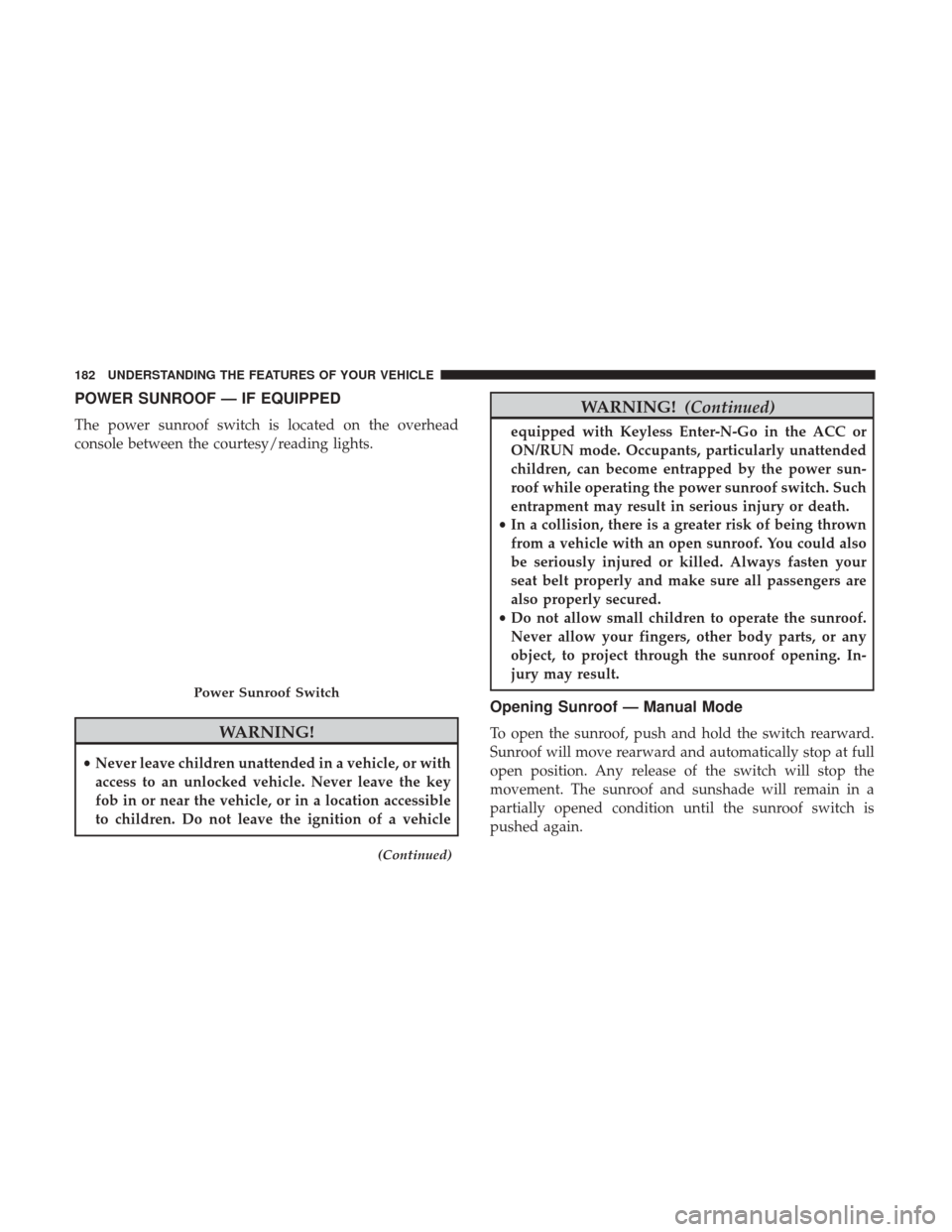
The power sunroof switch is located on the overhead
console between the courtesy/reading lights.
WARNING!
•Never leave children unattended in a vehicle, or with
access to an unlocked vehicle. Never leave the key
fob in or near the vehicle, or in a location accessible
to children. Do not leave the ignition of a vehicle
(Continued)
WARNING! (Continued)
equipped with Keyless Enter-N-Go in the ACC or
ON/RUN mode. Occupants, particularly unattended
children, can become entrapped by the power sun-
roof while operating the power sunroof switch. Such
entrapment may result in serious injury or death.
• In a collision, there is a greater risk of being thrown
from a vehicle with an open sunroof. You could also
be seriously injured or killed. Always fasten your
seat belt properly and make sure all passengers are
also properly secured.
• Do not allow small children to operate the sunroof.
Never allow your fingers, other body parts, or any
object, to project through the sunroof opening. In-
jury may result.
Opening Sunroof — Manual Mode
To open the sunroof, push and hold the switch rearward.
Sunroof will move rearward and automatically stop at full
open position. Any release of the switch will stop the
movement. The sunroof and sunshade will remain in a
partially opened condition until the sunroof switch is
pushed again.
Power Sunroof Switch
182 UNDERSTANDING THE FEATURES OF YOUR VEHICLE
Page 185 of 734

Closing Sunroof — Manual Mode
To close the sunroof, push and hold the switch forward.
Sunroof will move forward and automatically stop at full
closed position. Any release of the switch will stop the
movement and the sunroof will remain in a partially closed
condition until the sunroof switch is pushed again.
Opening Sunroof — Express
Push the switch rearward and release it within one-half
second and the sunroof will open automatically from any
position. The sunroof will open fully and stop automati-
cally. This is called “Express Open”. During Express Open
operation, any other actuation of the sunroof switch will
stop the sunroof.
Closing Sunroof — Express
Push the switch forward and release it within one-half
second and the sunroof will close automatically from any
position. The sunroof will close fully and stop automati-
cally. This is called “Express Close.” During Express Close
operation, any other actuation of the switch will stop the
sunroof.
Pinch Protect Feature
This feature will detect an obstruction in the opening of the
sunroof during Express Close operation. If an obstruction
in the path of the sunroof is detected, the sunroof will
automatically retract. Remove the obstruction if this oc-
curs.
NOTE:If three consecutive sunroof close attempts result in
Pinch Protect reversals, Pinch Protect will disable, and the
sunroof must be closed in Manual Mode.
Venting Sunroof — Express
Push and release the Vent button within one half second
and the sunroof will open to the vent position. This is
called “Express Vent” and it will occur regardless of
sunroof position. During Express Vent operation, any
movement of the switch will stop the sunroof.
Sunshade Operation
The sunshade can be opened manually. However, the
sunshade will open automatically as the sunroof opens.
NOTE: The sunshade cannot be closed if the sunroof is
open.
3
UNDERSTANDING THE FEATURES OF YOUR VEHICLE 183
Page 186 of 734
Wind Buffeting
Wind buffeting can be described as the perception of
pressure on the ears or a helicopter-type sound in the ears.
Your vehicle may exhibit wind buffeting with the windows
down, or the sunroof (if equipped) in certain open or
partially open positions. This is a normal occurrence and
can be minimized. If the buffeting occurs with the rear
windows open, open the front and rear windows together
to minimize the buffeting. If the buffeting occurs with the
sunroof open, adjust the sunroof opening to minimize the
buffeting or open any window.
Sunroof Maintenance
Use only a nonabrasive cleaner and a soft cloth to clean the
glass panel.
Ignition Off Operation
The power sunroof switch will remain active in Accessory
Delay for up to approximately ten minutes after the
ignition switch is turned to the lock position. Opening
either front door will cancel this feature.
NOTE:Ignition Off time is programmable through the
Uconnect System. Refer to “Uconnect Settings/Customer
Programmable Features” in “Understanding Your Instru-
ment Panel” for further information.
ELECTRICAL POWER OUTLETS
The auxiliary 12 Volt (13 Amp) power outlets can provide
power for in-cab accessories designed for use with the
standard “cigar lighter” plug. The 12 Volt power outlets
and USB Port (Charge Only) have a cap attached to the
outlet indicating “12V DC,” together with either a key
symbol, battery symbol, or USB symbol.
A key symbol indicates that the key must be in the
ON/RUN or ACC positions for the outlet to provide
power. The battery symbol indicates that the outlet is
connected to the battery, and can provide power at all
times.
NOTE: To ensure proper operation, a MOPAR knob and
element must be used.
CAUTION!
• Do not exceed the maximum power of 160 Watts
(13 Amps) at 12 Volts. If the 160 Watts (13 Amps)
power rating is exceeded, the fuse protecting the
system will need to be replaced.
(Continued)
184 UNDERSTANDING THE FEATURES OF YOUR VEHICLE
Page 187 of 734

CAUTION!(Continued)
•Power outlets are designed for accessory plugs only.
Do not insert any other object in the power outlets as
this will damage the outlet and blow the fuse.
Improper use of the power outlet can cause damage
not covered by your New Vehicle Limited Warranty.
The auxiliary power outlets can be found in the following
locations:
• Lower left and lower right of the center stack when
equipped with a bench seat.
Power Outlets — Center Stack
1 — Power Outlet
2 — USB Port (Charge Only)
3
UNDERSTANDING THE FEATURES OF YOUR VEHICLE 185
Page 188 of 734
•Center console when equipped with bucket seats. •Inside the upper lid of the center storage compartment
— if equipped.
Power Outlet — Center Console
USB Port (Charge Only) — Upper Lid
186 UNDERSTANDING THE FEATURES OF YOUR VEHICLE
Page 189 of 734
•Rear of the center console storage compartment — Quad
Cab or Crew Cab.
Power Outlet — Rear Center Console
Power Outlet — Rear Center Console Fuse
3
UNDERSTANDING THE FEATURES OF YOUR VEHICLE 187
Page 190 of 734
When the vehicle is turned off, be sure to unplug any
equipment as to not drain the battery of the vehicle. All
accessories connected to the outlet(s) should be removed or
turned off when the vehicle is not in use to protect the
battery against discharge.
WARNING!
To avoid serious injury or death:
•Only devices designed for use in this type of outlet
should be inserted into any 12 Volt outlet.
• Do not touch with wet hands.
• Close the lid when not in use and while driving the
vehicle.
• If this outlet is mishandled, it may cause an electric
shock and failure.
CAUTION!
• Many accessories that can be plugged in draw power
from the vehicle’s battery, even when not in use (i.e.,
cellular phones, etc.). Eventually, if plugged in long
enough, the vehicle’s battery will discharge suffi-
ciently to degrade battery life and/or prevent the
engine from starting.
• Accessories that draw higher power (i.e., coolers,
vacuum cleaners, lights, etc.), will discharge the
battery even more quickly. Only use these intermit-
tently and with greater caution.
(Continued)
Power Outlet Fuse Locations
1 — F104 Fuse 20 A Yellow Power Outlet Center Console Bin / USB
Port (Charge Only)
2 — F90–F91 Fuse 20 A Yellow Power Outlet Rear Center Console
3 — F93 Fuse 20 A Yellow Cigar Lighter Instrument Panel 188 UNDERSTANDING THE FEATURES OF YOUR VEHICLE