ECO mode Ram 2500 2017 Workshop Manual
[x] Cancel search | Manufacturer: RAM, Model Year: 2017, Model line: 2500, Model: Ram 2500 2017Pages: 734, PDF Size: 7.3 MB
Page 447 of 734
NOTE:The vehicle will automatically enter Aero Mode
when the vehicle speed remains between 62 mph (100 km/h)
and 66 mph (106 km/h) for greater than 20 seconds or if the
vehicle speed exceeds 66 mph (106 km/h).
• Normal Ride Height (NRH) – This is the standard
position of the suspension and is meant for normal
driving.
• Off-Road (OR) (Raises the vehicle approximately 1 in
[26 mm]) – This position is intended for off-roading use
only where maximum ground clearance is required. To
enter OR, push the “Up” button once from the NRH
position while vehicle speed is below 20 mph (32 km/h).
While in OR, if the vehicle speed exceeds 25 mph
(40 km/h) the vehicle height will be automatically
lowered to NRH. Off-Road may not be available due to
vehicle payload, an instrument cluster display message
will be shown when this occurs. Refer to “Instrument
Cluster Display” in “Understanding Your Instrument
Panel” for further information.
CAUTION!
If the vehicle is in Off-Road setting, be aware of your
surroundings, you may not have the clearance required
for certain areas and vehicle damage may occur.
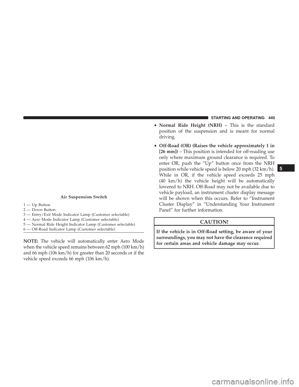
Air Suspension Switch
1 — Up Button
2 — Down Button
3 — Entry/Exit Mode Indicator Lamp (Customer selectable)
4 — Aero Mode Indicator Lamp (Customer selectable)
5 — Normal Ride Height Indicator Lamp (Customer selectable)
6 — Off-Road Indicator Lamp (Customer selectable)
5
STARTING AND OPERATING 445
Page 448 of 734
![Ram 2500 2017 Workshop Manual •Aero Mode (Lowers the vehicle approximately .6 in
[15 mm]) – This position provides improved aerody-
namics by lowering the vehicle. The vehicle will auto-
matically enter Aero Mode when the vehi Ram 2500 2017 Workshop Manual •Aero Mode (Lowers the vehicle approximately .6 in
[15 mm]) – This position provides improved aerody-
namics by lowering the vehicle. The vehicle will auto-
matically enter Aero Mode when the vehi](/img/34/12560/w960_12560-447.png)
•Aero Mode (Lowers the vehicle approximately .6 in
[15 mm]) – This position provides improved aerody-
namics by lowering the vehicle. The vehicle will auto-
matically enter Aero Mode when the vehicle speed
remains between 62 mph (100 km/h) and 66 mph
(106 km/h) for greater than 20 seconds or if the vehicle
speed exceeds 66 mph (106 km/h). The vehicle will
return to NRH from Aero Mode if the vehicle speed
remains between 30 mph (48 km/h) and 35 mph
(56 km/h) for greater than 20 seconds or if the vehicle
speed falls below 30 mph (48 km/h).
NOTE: Speed thresholds for raising the vehicle only apply
if Automatic Aero Mode is enabled.
• To enter Aero Mode manually push the down button
once from NRH at any vehicle speed. To return to NRH
push the up button once while vehicle speed is less than
56 mph (90 km/h).
NOTE: Automatic Aero Mode may be disabled through
vehicle settings on your Uconnect Radio when equipped
with UConnect 5.0, 8.4A, or 8.4AN. Refer to “Uconnect
Settings” in “Understanding Your Instrument Panel” for
further information. •
Entry/Exit Mode (Lowers the vehicle approximately
3 in [73 mm]) – This position lowers the vehicle for
easier passenger entry and exit as well as lowering the
rear of the vehicle for easier loading and unloading of
cargo. To enter Entry/Exit Mode, push the “Down”
button twice from the NRH while the vehicle speed is
below 33 mph (53 km/h). Once the vehicle speed goes
below 15 mph (24 km/h) the vehicle height will begin to
lower. If the vehicle speed remains between 15 mph
(24 km/h) and 25 mph (40 km/h) for greater than
60 seconds, or the vehicle speed exceeds 25 mph
(40 km/h) the Entry/Exit change will be cancelled. To
return to Normal Height Mode, push the “Up” button
twice while in Entry/Exit or drive the vehicle over
15 mph (24 km/h). Entry/Exit mode may not be avail-
able due to vehicle payload, an instrument cluster
display message will be shown when this occurs. Refer
to “Instrument Cluster Display” in “Understanding
Your Instrument Panel” for further information.
CAUTION!
When in ENTRY/EXIT setting, be aware of your sur-
roundings, you may not have the clearance required for
certain areas and vehicle damage may occur.
446 STARTING AND OPERATING
Page 453 of 734

Normal Ride Height (NRH)– This is the standard position
of the suspension and is meant for normal driving. It will
automatically adjust to maintain the rear ride height as
conditions change.
Alternate Trailer Height (ATH) – Lowers the vehicle
approximately 1 in (25 mm) for a level truck, to be used as
required while trailer towing. It will automatically adjust
to maintain the rear ride height as conditions change.
Trailer Decoupling/Unloading - The air suspension sys-
tem will load level (lower/exhaust only) for up to 10 min-
utes after the vehicle is turned off. This allows for easy
removal of a trailer and/or load from the back of the truck
by maintaining the ride height. After 10 minutes you will
need to turn the ignition to the run position for the air
suspension to maintain ride height. If the air suspension
system is disabled using the settings menu (Tire Jack Mode,
Transport Mode or Alignment Mode) the system will
remain disabled when the vehicle is turned off. Reactivat-
ing the air suspension can be accomplished via the settings
menu or driving the vehicle above 5 mph (8 km/h) for Tire
Jack Mode or Alignment Mode and 16 mph (26 km/h) for
Transport Mode. NOTE:
•
Most 3500 models will not lower to Alternate Trailer
Height (ATH) when unloaded.
• Refer to “Trailer Towing” in “Starting And Operating”
for further information.
Ignition OFF Behavior
For a predetermined amount of time after the ignition is off
the air suspension may adjust to maintain a proper appear-
ance.
WARNING!
The air suspension system uses a high pressure vol-
ume of air to operate the system. To avoid personal
injury or damage to the system, see your authorized
dealer for service.
5
STARTING AND OPERATING 451
Page 455 of 734
Instrument Cluster Display Messages
When the appropriate conditions exist, a message will
appear in the instrument cluster display. Refer to “Instru-
ment Cluster Display” in “Understanding Your Instrument
Panel” for further information.
An audible chime will be heard whenever a system error
has been detected.
See your authorized dealer for system service if normal
operation does not resume.
Operation
Pushing the Alternate Trailer Height (ATH) button once
while at Normal Ride Height (NRH), will lower the vehicle
to Alternate Trailer Height (ATH) and will illuminate the
LED.
NOTE:The LED will continuously blink until vehicle
Alternate Trailer Height (ATH) has been achieved and the
LED will turn off.
Pushing the Alternate Trailer Height (ATH) again will raise
the vehicle to Normal Ride Height (NRH).
NOTE: The LED will continuously blink until Normal Ride
Height (NRH) has been achieved. •
Transport Mode – No indicator lamps will be illumi-
nated. Transport Mode is disabled by driving the ve-
hicle.
• Tire/Jack Mode – No indicator lamps will be illumi-
nated. Tire/Jack Mode is disabled by driving the vehicle.
• Wheel Alignment Mode – No indicator lamps will be
illuminated. Wheel Alignment Mode is disabled by
driving the vehicle.
AXLE LOCKER SYSTEM — POWER WAGON
MODELS ONLY (IF EQUIPPED)
This vehicle is equipped with electronically locking front
and rear differentials. These differentials, when engaged,
mechanically lock together the axle shafts forcing the
wheels to spin at an equal rate. This allows the vehicle to
maintain its momentum and prevents it from becoming
stuck. The locking front and rear differentials should only
be engaged during low-speed, extreme off-road situations
where one wheel is likely to not be in contact with the
ground. It is not recommended to drive the vehicle with
the differentials locked on pavement due to the reduced
ability to turn and speed limitations.
5
STARTING AND OPERATING 453
Page 456 of 734
CAUTION!
•Do not lock the front or rear axle on hard surfaced
roads. The ability to steer the vehicle is reduced and
damage to the drivetrain may occur when the axles
are locked on hard surfaced roads.
• Do not try to lock the rear axle if the vehicle is stuck
and the tires are spinning. You can damage drivetrain
components. Lock the rear axle before attempting
situations or navigating terrain, which could possi-
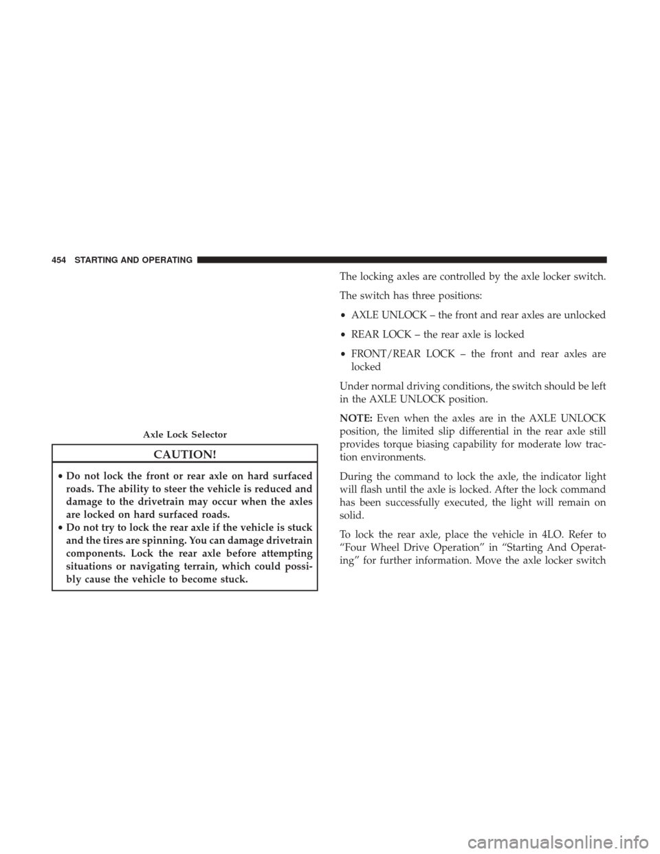
bly cause the vehicle to become stuck. The locking axles are controlled by the axle locker switch.
The switch has three positions:
•
AXLE UNLOCK – the front and rear axles are unlocked
• REAR LOCK – the rear axle is locked
• FRONT/REAR LOCK – the front and rear axles are
locked
Under normal driving conditions, the switch should be left
in the AXLE UNLOCK position.
NOTE: Even when the axles are in the AXLE UNLOCK
position, the limited slip differential in the rear axle still
provides torque biasing capability for moderate low trac-
tion environments.
During the command to lock the axle, the indicator light
will flash until the axle is locked. After the lock command
has been successfully executed, the light will remain on
solid.
To lock the rear axle, place the vehicle in 4LO. Refer to
“Four Wheel Drive Operation” in “Starting And Operat-
ing” for further information. Move the axle locker switch
Axle Lock Selector
454 STARTING AND OPERATING
Page 458 of 734

This system is controlled by the electronic control sway bar
switch located on the instrument panel.
The switch has two positions; On-Road and Off-Road. The
system is normally in the On-Road mode, indicated by a
solid green light. The stabilizer/sway bar should remain in
the On-Road mode during normal driving conditions.WARNING!
Do not disconnect the stabilizer bar and drive on hard
surfaced roads or at speeds above 18 mph (29 km/h),
you may lose control of the vehicle, which could result
in serious injury or death. The front stabilizer bar
enhances vehicle stability and assists in maintaining
control of the vehicle. The system monitors vehicle
speed and will attempt to reconnect the stabilizer bar
at speeds over 18 mph (29 km/h). This is indicated by a
flashing off road light and solid on road light. Once
vehicle speed is reduced below 14 mph (22 km/h), the
system will attempt to return to the Off-Road mode.
To disconnect the stabilizer/sway bar, shift to either 4HI or
4LO as shown in “Four Wheel Drive Operation” and push
the right hand Off Road stabilizer/sway bar button to
obtain the Off-Road position. The amber indicator light
will flash until the stabilizer/sway bar has been fully
disconnected.
Sway Bar Disconnect Buttons
456 STARTING AND OPERATING
Page 459 of 734
NOTE:The stabilizer/sway bar may be torque locked due
to left and right suspension height differences. This condi-
tion is due to driving surface differences or vehicle loading.
In order for the stabilizer/sway bar to disconnect/
reconnect, the right and left halves of the bar must be
aligned. This alignment may require that the vehicle be
driven onto level ground or rocked from side to side.
To return to the On-Road mode; push the left hand On
Road stabilizer/sway bar button.
WARNING!
If the stabilizer/sway bar will not return to On-Road
mode, vehicle stability is reduced. Do not attempt to
drive the vehicle over 18 mph (29 km/h). Driving faster
than 18 mph (29 km/h) may cause loss of control of the
vehicle, which could result in serious injury or death.
Contact your local service center for assistance.
SAFE OFF-ROAD DRIVING — POWER WAGON
ONLY
Off-Road Driving Tips And Vehicle Characteristics
Your vehicle has excellent on and off-road capabilities.
These off-road capabilities will allow you to explore those
wilderness trails where few travel, providing a source of
exciting and satisfying recreation. Before you venture out,
you should contact your local governmental agency to
determine the designated off-road vehicle (ORV) trails or
recreation areas. You should always tread lightly and only
use established roads, trails or ORV recreational areas.
The National Forest Service, Bureau of Land Management,
or local Department of Natural Resources are a wealth of
information and usually have maps with marked trails.
Skid Plates And Underbody Protection
Steel skid plates protect the major driveline components of
the truck including the fuel tank, transfer case and steering
damper. In addition, this vehicle is equipped with boxed
cross members and fore/aft rails. This additional protec-
tion allows the vehicle to be utilized in severe off-road
situations that would be considered impassable by a nor-
mal truck.
5
STARTING AND OPERATING 457
Page 494 of 734
Power Steering Fluid Check — 2500/3500 Models
Checking the power steering fluid level at a defined service
interval is not required. The fluid should only be checked
if a leak is suspected, abnormal noises are apparent,
and/or the system is not functioning as anticipated. Coor-
dinate inspection efforts through an authorized dealer.
CAUTION!
Do not use chemical flushes in your power steering
system as the chemicals can damage your power steer-
ing components. Such damage is not covered by the
New Vehicle Limited Warranty.
WARNING!
Fluid level should be checked on a level surface and
with the engine off to prevent injury from moving
parts and to ensure accurate fluid level reading. Do not
overfill. Use only manufacturer’s recommended power
steering fluid.
If necessary, add fluid to restore to the proper indicated
level. With a clean cloth, wipe any spilled fluid from all
surfaces. Refer to “Fluids, Lubricants, And Genuine Parts”
in “Maintaining Your Vehicle” for further information.
FUEL SAVER TECHNOLOGY 5.7L/6.4L ENGINES
ONLY — IF EQUIPPED
This feature offers improved fuel economy by shutting off
four of the engine’s eight cylinders during light load and
cruise conditions. The system is automatic with no driver
inputs or additional driving skills required.
NOTE: This system may take some time to return to full
functionality after a battery disconnect.
PARKING BRAKE
Before leaving the vehicle, make sure that the parking
brake is fully applied. Also, be certain to leave the trans-
mission in PARK.
The foot operated parking brake is located below the lower
left corner of the instrument panel. To apply the park
brake, firmly push the park brake pedal fully. To release the
parking brake, pull the parking brake release handle.
492 STARTING AND OPERATING
Page 502 of 734
6. Push the “ESC Off” button located in the lower switchbank below the climate control four times within twenty
seconds. The “ESC Off Indicator Light” should turn on
and turn off two times.
7. Rotate the steering wheel back to center and then an additional slightly more than one-half turn to the right.
8. Turn the ignition switch to the OFF position and then back to the ON position. If the sequence was completed
properly, the “ESC Off Indicator Light” will blink sev-
eral times to confirm HSA is disabled.
9. Repeat these steps if you want to return this feature to its previous setting.
Traction Control System (TCS)
This system monitors the amount of wheel spin of each of
the driven wheels. If wheel spin is detected, the TCS may
apply brake pressure to the spinning wheel(s) and/or
reduce engine power to provide enhanced acceleration and
stability. A feature of the TCS, Brake Limited Differential
(BLD), functions similar to a limited slip differential and
controls the wheel spin across a driven axle. If one wheel
on a driven axle is spinning faster than the other, the
system will apply the brake of the spinning wheel. This will allow more engine torque to be applied to the wheel
that is not spinning. BLD may remain enabled even if TCS
and ESC are in a reduced mode.
Electronic Stability Control (ESC)
This system enhances directional control and stability of
the vehicle under various driving conditions. ESC corrects
for oversteering or understeering of the vehicle by apply-
ing the brake of the appropriate wheel(s) to assist in
counteracting the oversteer or understeer condition. En-
gine power may also be reduced to help the vehicle
maintain the desired path.
ESC uses sensors in the vehicle to determine the vehicle
path intended by the driver and compares it to the actual
path of the vehicle. When the actual path does not match
the intended path, ESC applies the brake of the appropriate
wheel to assist in counteracting the oversteer or understeer
condition.
•
Oversteer - when the vehicle is turning more than
appropriate for the steering wheel position.
• Understeer - when the vehicle is turning less than
appropriate for the steering wheel position.
500 STARTING AND OPERATING
Page 503 of 734
The “ESC Activation/Malfunction Indicator Light” located
in the instrument cluster will start to flash as soon as the ESC
system becomes active. The “ESC Activation/Malfunction
Indicator Light” also flashes when the TCS is active. If the
“ESC Activation/Malfunction Indicator Light” begins to
flash during acceleration, ease up on the accelerator and
apply as little throttle as possible. Be sure to adapt your
speed and driving to the prevailing road conditions.
WARNING!
•Electronic Stability Control (ESC) cannot prevent the
natural laws of physics from acting on the vehicle, nor
can it increase the traction afforded by prevailing road
conditions. ESC cannot prevent accidents, including
those resulting from excessive speed in turns, driving
on very slippery surfaces, or hydroplaning. ESC also
cannot prevent accidents resulting from loss of vehicle
control due to inappropriate driver input for the con-
ditions. Only a safe, attentive, and skillful driver can
prevent accidents. The capabilities of an ESC
equipped vehicle must never be exploited in a reckless
or dangerous manner which could jeopardize the us-
er ’s safety or the safety of others.
(Continued)
WARNING! (Continued)
•Vehicle modifications, or failure to properly main-
tain your vehicle, may change the handling charac-
teristics of your vehicle, and may negatively affect
the performance of the ESC system. Changes to the
steering system, suspension, braking system, tire
type and size or wheel size may adversely affect ESC
performance. Improperly inflated and unevenly
worn tires may also degrade ESC performance. Any
vehicle modification or poor vehicle maintenance
that reduces the effectiveness of the ESC system can
increase the risk of loss of vehicle control, vehicle
rollover, personal injury and death.
ESC Operating Modes
NOTE: Depending upon model and mode of operation, the
ESC system may have multiple operating modes.
ESC On
This is the normal operating mode for the ESC. Whenever
the vehicle is started, the ESC system will be in this mode.
This mode should be used for most driving conditions.
Alternate ESC modes should only be used for specific
reasons as noted in the following paragraphs.
5
STARTING AND OPERATING 501