instrument panel Ram 2500 2018 Owner's Manual
[x] Cancel search | Manufacturer: RAM, Model Year: 2018, Model line: 2500, Model: Ram 2500 2018Pages: 372, PDF Size: 7.1 MB
Page 32 of 372
This feature can be programmed through the
Uconnect system. Refer to “Uconnect Set-
tings” in “Multimedia” in the Owner’s
Manual for further information.
WARNING!
• Persons who are unable to feel pain tothe skin because of advanced age,
chronic illness, diabetes, spinal cord in-
jury, medication, alcohol use, exhaus-
tion, or other physical conditions must
exercise care when using the steering
wheel heater. It may cause burns even at
low temperatures, especially if used for
long periods.
• Do not place anything on the steering
wheel that insulates against heat, such
as a blanket or steering wheel covers of
any type and material. This may cause
the steering wheel heater to overheat.
DRIVER ADJUSTABLE PEDALS — IF
EQUIPPED
The adjustable pedals system is designed to
allow a greater range of driver comfort for
steering wheel tilt and seat position. This
feature allows the brake, accelerator, and
clutch pedals (if equipped) to move toward or
away from the driver to provide improved
position with the steering wheel.
The adjustable pedal switch is located to the
left side of the steering column.
• The pedals can be adjusted with the igni-
tion OFF.
• The pedals cannotbe adjusted when the
vehicle is in REVERSE or when the Speed
Control System is on. The following mes-
sages will appear on vehicles equipped with
an instrument cluster display if the pedals
are attempted to be adjusted when the
system is locked out: “Adjustable Pedal
Disabled — Cruise Control Engaged” or
“Adjustable Pedal Disabled — Vehicle In
Reverse”. NOTE:
• Always adjust the pedals to a position that
allows full pedal travel.
• Further small adjustments may be neces- sary to find the best possible seat/pedal
position.
• For vehicles equipped with Driver Memory Seat, you can use your remote keyless entry
key fob or the memory switch on the driver’s
door trim panel to return the adjustable
pedals to pre-programmed positions. Refer
to “Driver Memory Seat” in “Getting To
Know Your Vehicle” for further information.
WARNING!
Do not adjust the pedals while the vehicle
is moving. You could lose control and have
an accident. Always adjust the pedals
while the vehicle is parked.
CAUTION!
Do not place any article under the adjust-
able pedals or impede its ability to move,
as it may cause damage to the pedal con-
GETTING TO KNOW YOUR VEHICLE
30
Page 34 of 372
EXTERIOR LIGHTS
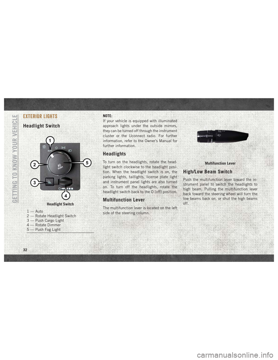
Headlight Switch
NOTE:
If your vehicle is equipped with illuminated
approach lights under the outside mirrors,
they can be turned off through the instrument
cluster or the Uconnect radio. For further
information, refer to the Owner’s Manual for
further information.
Headlights
To turn on the headlights, rotate the head-
light switch clockwise to the headlight posi-
tion. When the headlight switch is on, the
parking lights, taillights, license plate light
and instrument panel lights are also turned
on. To turn off the headlights, rotate the
headlight switch back to the O (off) position.
Multifunction Lever
The multifunction lever is located on the left
side of the steering column.
High/Low Beam Switch
Push the multifunction lever toward the in-
strument panel to switch the headlights to
high beam. Pulling the multifunction lever
back toward the steering wheel will turn the
low beams back on, or shut the high beams
off.
Headlight Switch
1 — Auto
2 — Rotate Headlight Switch
3 — Push Cargo Light
4 — Rotate Dimmer
5 — Push Fog Light
Multifunction Lever
GETTING TO KNOW YOUR VEHICLE
32
Page 35 of 372
Automatic High Beam Headlamp
Control — If Equipped
The Automatic High Beam Headlamp Control
system provides increased forward lighting at
night by automating high beam control
through the use of a digital camera mounted
on the inside rearview mirror. This camera
detects vehicle specific light and automati-
cally switches from high beams to low beams
until the approaching vehicle is out of view.
NOTE:
• The Automatic High Beam Headlamp Con-trol can be turned on or off by selecting
“ON” under “Auto High Beam” within your
Uconnect settings, as well as turning the
headlight switch to the AUTO position. Re-
fer to “Uconnect Settings” in “Multimedia”
in the Owner’s Manual for further informa-
tion.
• Broken, muddy, or obstructed headlights and taillights of vehicles in the field of view
will cause headlights to remain on longer
(closer to the vehicle). Also, dirt, film, and
other obstructions on the windshield or
camera lens will cause the system to func-
tion improperly. If the windshield or Automatic High Beam
Headlamp Control mirror is replaced, the
mirror must be re-aimed to ensure proper
performance. See a local authorized dealer.
Automatic Headlights — If
Equipped
This system automatically turns the head-
lights on or off according to ambient light
levels. To turn the system on, rotate the
headlight switch counterclockwise to the
AUTO position. When the system is on, the
headlight time delay feature is also on. This
means the headlights will stay on for up to
90 seconds after you place the ignition into
the OFF position. The headlight time delay
can be programmed 0/30/60/90 seconds.
Refer to “Uconnect Settings” in “Multime-
dia” in the Owner’s Manual for further infor-
mation.
To turn the automatic system off, move the
headlight switch out of the AUTO position.
NOTE:
The engine must be running before the head-
lights will turn on in the Automatic Mode.
Parking Lights And Panel Lights
To turn on the parking lights and instrument
panel lights, rotate the headlight switch
clockwise. To turn off the parking lights,
rotate the headlight switch back to the O (off)
position.
Turn Signals
Move the multifunction lever up or down and
the arrows on each side of the instrument
cluster display will flash to show proper op-
eration of the front and rear turn signal lights.
NOTE:
If either light remains on and does not flash,
or there is a very fast flash rate, check for a
defective outside light bulb. If an indicator
fails to light when the lever is moved, it would
suggest that the indicator bulb is defective.
33
Page 41 of 372
IconDescription
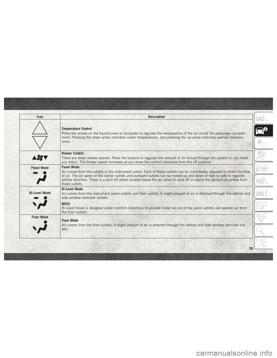
Temperature Control
Press the arrows on the touchscreen or faceplate to regulate the temperature of the air inside the passenger compart-
ment. Pressing the down arrow indicates cooler temperatures, and pressing the up arrow indicates warmer tempera-
tures.
Blower Control
There are seven blower speeds. Press the buttons to regulate the amount of air forced through the system in any mode
you select. The blower speed increases as you move the control clockwise from the off position.
Panel Mode
Panel Mode
Air comes from the outlets in the instrument panel. Each of these outlets can be individually adjusted to direct the flow
of air. The air vanes of the center outlets and outboard outlets can be moved up and down or side to side to regulate
airflow direction. There is a shut off wheel located below the air vanes to shut off or adjust the amount of airflow from
these outlets.
Bi-Level Mode
Bi-Level Mode
Air comes from the instrument panel outlets and floor outlets. A slight amount of air is directed through the defrost and
side window demister outlets.
NOTE:
Bi-Level mode is designed under comfort conditions to provide cooler air out of the panel outlets and warmer air from
the floor outlets.
Floor Mode
Floor Mode
Air comes from the floor outlets. A slight amount of air is directed through the defrost and side window demister out-
lets.
39
Page 47 of 372
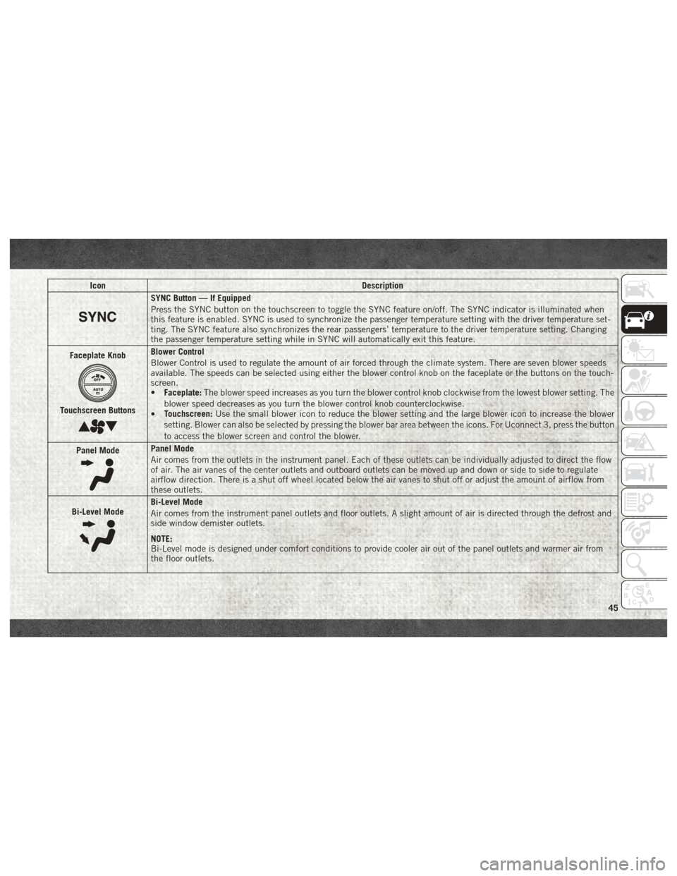
IconDescription
SYNC Button — If Equipped
Press the SYNC button on the touchscreen to toggle the SYNC feature on/off. The SYNC indicator is illuminated when
this feature is enabled. SYNC is used to synchronize the passenger temperature setting with the driver temperature set-
ting. The SYNC feature also synchronizes the rear passengers’ temperature to the driver temperature setting. Changing
the passenger temperature setting while in SYNC will automatically exit this feature.
Faceplate Knob
Touchscreen Buttons
Blower Control
Blower Control is used to regulate the amount of air forced through the climate system. There are seven blower speeds
available. The speeds can be selected using either the blower control knob on the faceplate or the buttons on the touch-
screen.
• Faceplate: The blower speed increases as you turn the blower control knob clockwise from the lowest blower setting. The
blower speed decreases as you turn the blower control knob counterclockwise.
• Touchscreen:
Use the small blower icon to reduce the blower setting and the large blower icon to increase the blower
setting. Blower can also be selected by pressing the blower bar area between the icons. For Uconnect 3, press the button
to access the blower screen and control the blower.
Panel Mode
Panel Mode
Air comes from the outlets in the instrument panel. Each of these outlets can be individually adjusted to direct the flow
of air. The air vanes of the center outlets and outboard outlets can be moved up and down or side to side to regulate
airflow direction. There is a shut off wheel located below the air vanes to shut off or adjust the amount of airflow from
these outlets.
Bi-Level Mode
Bi-Level Mode
Air comes from the instrument panel outlets and floor outlets. A slight amount of air is directed through the defrost and
side window demister outlets.
NOTE:
Bi-Level mode is designed under comfort conditions to provide cooler air out of the panel outlets and warmer air from
the floor outlets.
45
Page 52 of 372
will close fully and stop automatically. This is
called “Express Close”. During Express Close
operation, any other actuation of the switch
will stop the sunroof.
Manual
To close the sunroof, push and hold the
switch in the forward position. Any release of
the switch will stop the movement and the
sunroof will remain in a partially closed con-
dition until the sunroof switch is pushed
again.
Wind Buffeting
Wind buffeting can be described as the per-
ception of pressure on the ears or a
helicopter-type sound in the ears. Your ve-
hicle may exhibit wind buffeting with the
windows down, or the sunroof (if equipped) in
certain open or partially open positions. This
is a normal occurrence and can be mini-
mized. If the buffeting occurs with the rear
windows open, then open the front and rear
windows together to minimize the buffeting.
If the buffeting occurs with the sunroof open,
adjust the sunroof opening to minimize the
buffeting or open any window.
Pinch Protect Feature
This feature will detect an obstruction in the
closing of the sunroof during the Express
Close operation. If an obstruction in the path
of the sunroof is detected, the sunroof will
automatically retract. Remove the obstruc-
tion if this occurs.
NOTE:
If three consecutive sunroof close attempts
result in Pinch Protect reversals, Pinch Pro-
tect will disable and the sunroof must be
closed in Manual Mode.
Venting Sunroof — Express
Push and release the Vent button within one
half second and the sunroof will open to the
vent position. This is called “Express Vent”
and it will occur regardless of sunroof posi-
tion. During Express Vent operation, any
movement of the switch will stop the sunroof.
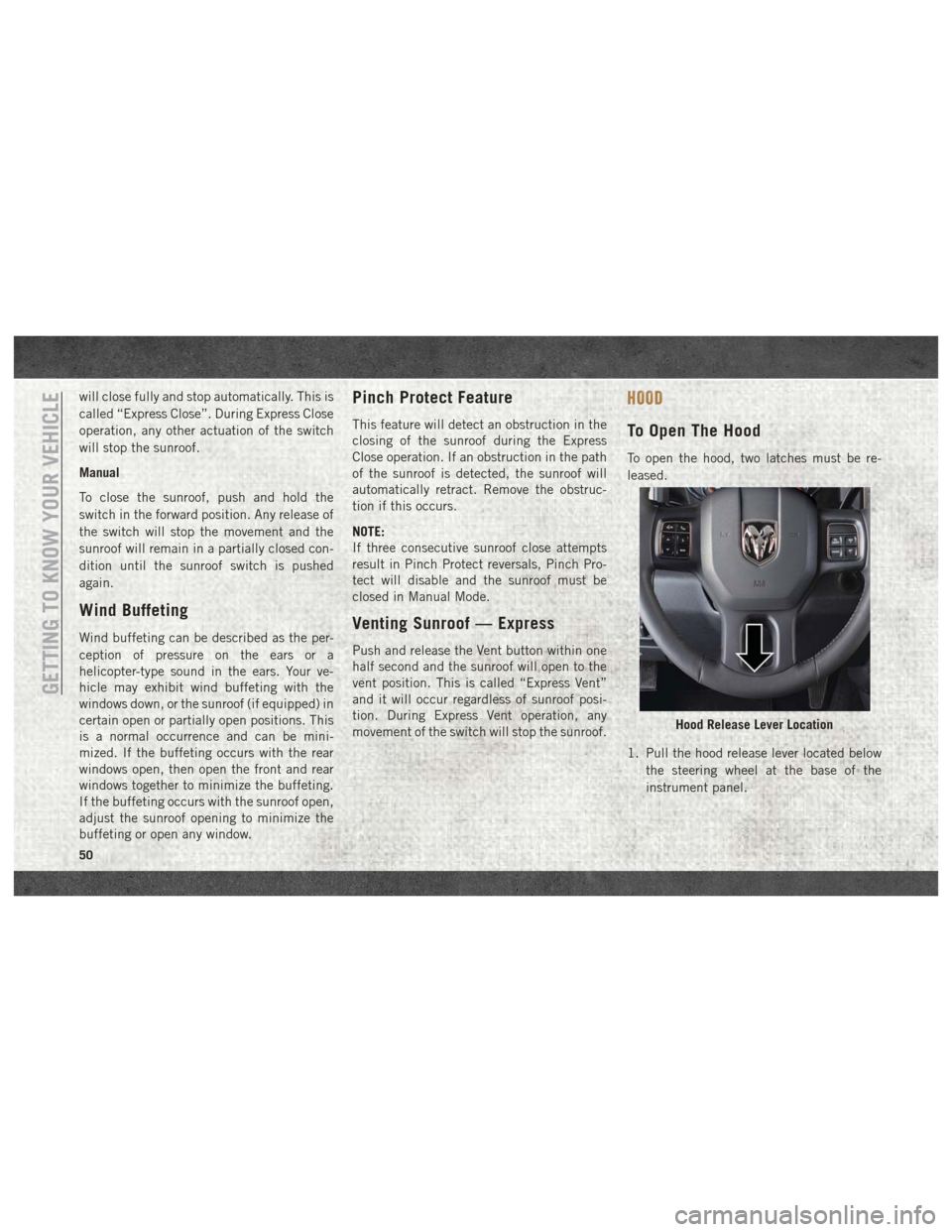
HOOD
To Open The Hood
To open the hood, two latches must be re-
leased.
1. Pull the hood release lever located belowthe steering wheel at the base of the
instrument panel.
Hood Release Lever Location
GETTING TO KNOW YOUR VEHICLE
50
Page 57 of 372
2. This device must accept any interferencereceived, including interference that may
cause undesired operation.
NOTE:
Changes or modifications not expressly ap-
proved by the party responsible for compli-
ance could void the user’s authority to oper-
ate the equipment.
INTERNAL EQUIPMENT
Electrical Power Outlets
The auxiliary 12 Volt (13 Amp) power outlets
can provide power for in-cab accessories de-
signed for use with the standard “cigar
lighter” plug. The 12 Volt power outlets and
USB Port (Charge Only) have a cap attached
to the outlet indicating “12V DC,” together
with either a key symbol, battery symbol, or
USB symbol. A key symbol indicates that the key must be
in the ON/RUN or ACC positions for the outlet
to provide power. The battery symbol indi-
cates that the outlet is connected to the
battery, and can provide power at all times.
NOTE:
To ensure proper operation, a Mopar knob
and element must be used.
CAUTION!
• Do not exceed the maximum power of
160 Watts (13 Amps) at 12 Volts. If the
160 Watts (13 Amps) power rating is
exceeded, the fuse protecting the sys-
tem will need to be replaced.
• Power outlets are designed for accessory
plugs only. Do not insert any other object
in the power outlets as this will damage
the outlet and blow the fuse. Improper
use of the power outlet can cause dam-
age not covered by your New Vehicle
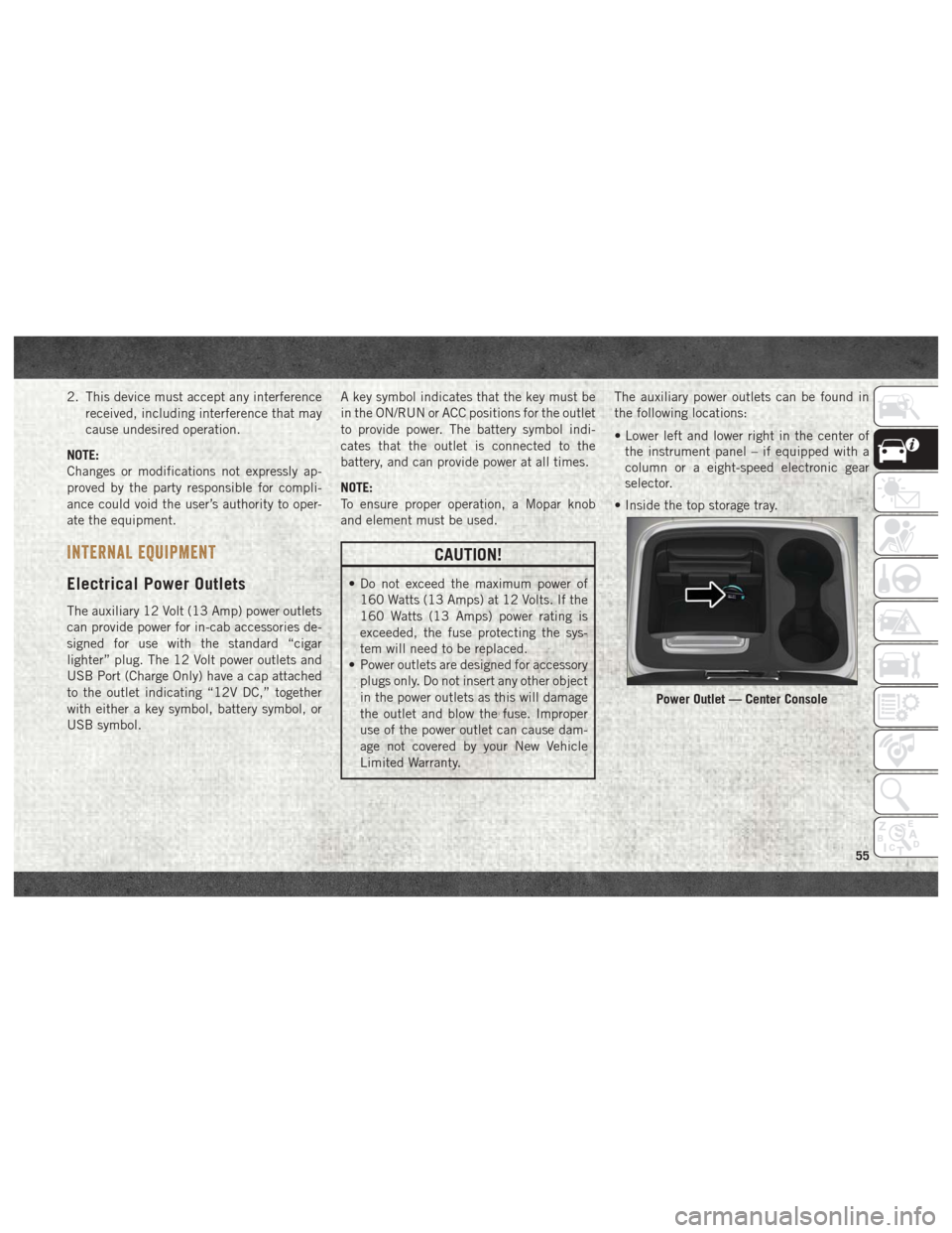
Limited Warranty. The auxiliary power outlets can be found in
the following locations:
• Lower left and lower right in the center of
the instrument panel – if equipped with a
column or a eight-speed electronic gear
selector.
• Inside the top storage tray.
Power Outlet — Center Console
55
Page 58 of 372
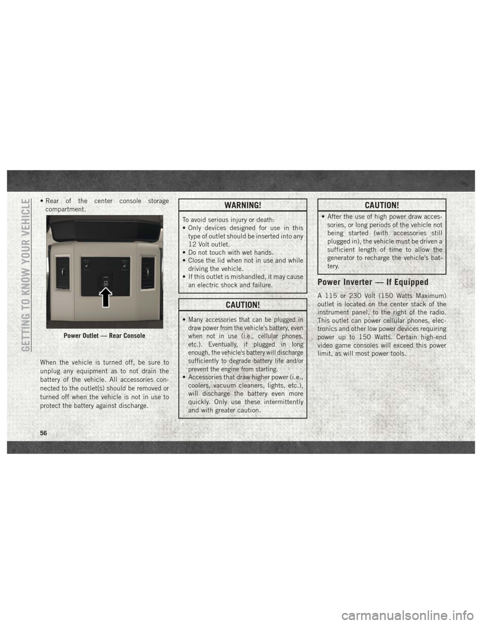
• Rear of the center console storagecompartment.
When the vehicle is turned off, be sure to
unplug any equipment as to not drain the
battery of the vehicle. All accessories con-
nected to the outlet(s) should be removed or
turned off when the vehicle is not in use to
protect the battery against discharge.WARNING!
To avoid serious injury or death:
• Only devices designed for use in this type of outlet should be inserted into any
12 Volt outlet.
• Do not touch with wet hands.
• Close the lid when not in use and while
driving the vehicle.
• If this outlet is mishandled, it may cause
an electric shock and failure.
CAUTION!
•Many accessories that can be plugged in
draw power from the vehicle's battery, even
when not in use (i.e., cellular phones,
etc.). Eventually, if plugged in long
enough, the vehicle's battery will discharge
sufficiently to degrade battery life and/or
prevent the engine from starting.
• Accessories that draw higher power (i.e.,coolers, vacuum cleaners, lights, etc.),
will discharge the battery even more
quickly. Only use these intermittently
and with greater caution.
CAUTION!
• After the use of high power draw acces-sories, or long periods of the vehicle not
being started (with accessories still
plugged in), the vehicle must be driven a
sufficient length of time to allow the
generator to recharge the vehicle's bat-
tery.
Power Inverter — If Equipped
A 115 or 230 Volt (150 Watts Maximum)
outlet is located on the center stack of the
instrument panel, to the right of the radio.
This outlet can power cellular phones, elec-
tronics and other low power devices requiring
power up to 150 Watts. Certain high-end
video game consoles will exceed this power
limit, as will most power tools.
Power Outlet — Rear Console
GETTING TO KNOW YOUR VEHICLE
56
Page 67 of 372
GETTING TO KNOW YOUR INSTRUMENT PANEL
INSTRUMENT CLUSTER DISPLAY.....66
Instrument Cluster Display Controls ....66
Diesel Messages And Warnings — 3.0L
Diesel Engine .................67
Diesel Messages And Warnings — 6.7L
Cummins Diesel Engine ...........70
Oil Life Reset .................74
Instrument Cluster Display Programmable
Features ....................75
WARNING LIGHTS AND MESSAGES ....76
Red Warning Lights..............76
Yellow Warning Lights ............78
Yellow Indicator Lights ............82
Green Indicator Lights ............83
White Indicator Lights ............84
Blue Indicator Lights .............84
ONBOARD DIAGNOSTIC SYSTEM —
OBDII .....................84
Onboard Diagnostic System (OBD II)
Cybersecurity.................85
GETTING TO KNOW YOUR INSTRUMENT PANEL
65
Page 68 of 372
INSTRUMENT CLUSTER DISPLAY
Your vehicle may be equipped with an instru-
ment cluster display, which offers useful in-
formation to the driver. With the ignition in
the STOP/OFF mode, opening/closing of a
door will activate the display for viewing, and
display the total miles, or kilometers, in the
odometer. Your instrument cluster display is
designed to display important information
about your vehicle’s systems and features.
Using a driver interactive display located on
the instrument panel, your instrument clus-
ter display can show you how systems are
working and give you warnings when they are
not. The steering wheel mounted controls
allow you to scroll through the main menus
and submenus. You can access the specific
information you want and make selections
and adjustments.
Instrument Cluster Display
Controls
The instrument cluster display features a
driver-interactive display that is located in
the instrument cluster.
The instrument cluster display menu items
may consist of the following:
• Speedometer
• Vehicle Info
• Fuel Economy Info
• Trip A
• Trip B
• Audio
• Trailer Tow
• Stored Messages
• Screen Setup
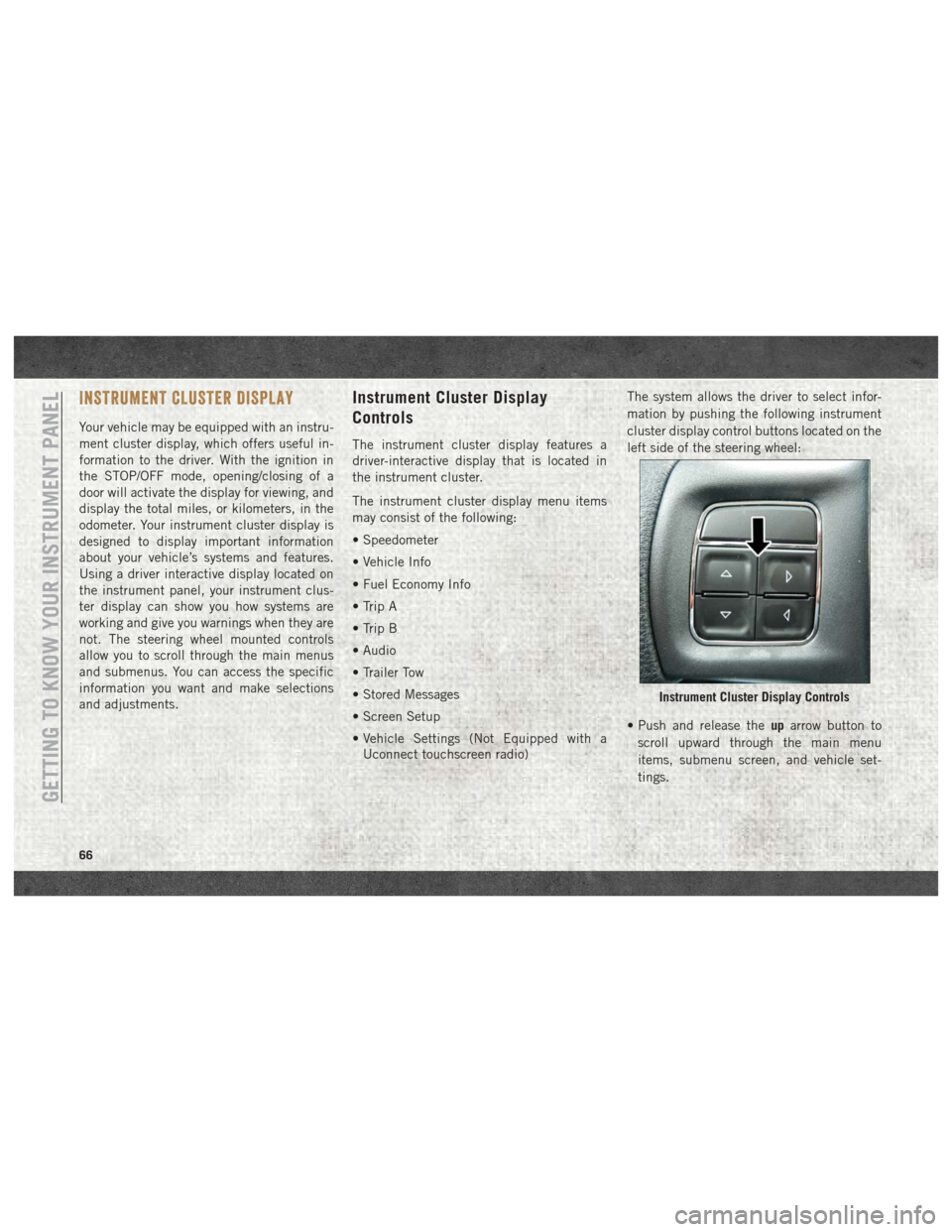
• Vehicle Settings (Not Equipped with aUconnect touchscreen radio) The system allows the driver to select infor-
mation by pushing the following instrument
cluster display control buttons located on the
left side of the steering wheel:
• Push and release the
uparrow button to
scroll upward through the main menu
items, submenu screen, and vehicle set-
tings.
Instrument Cluster Display Controls
GETTING TO KNOW YOUR INSTRUMENT PANEL
66