wheel Ram 2500 2018 Owner's Manual
[x] Cancel search | Manufacturer: RAM, Model Year: 2018, Model line: 2500, Model: Ram 2500 2018Pages: 372, PDF Size: 7.1 MB
Page 59 of 372

The power inverter is designed with built-in
overload protection. If the power rating of
150 Watts is exceeded, the power inverter
will automatically shut down. Once the elec-
trical device has been removed from the out-
let the inverter should automatically reset.
To turn on the power outlet, simply plug in the
device. The outlet automatically turns off
when the device is unplugged.NOTE:
• The Power Inverter will only turn on if the
ignition is in the ACC or ON/RUN position
• Due to built-in overload protection, the power inverter will shut down if the power
rating is exceeded.
WARNING!
To avoid serious injury or death:
• Do not insert any objects into the recep-
tacles.
• Do not touch with wet hands.
• Close the lid when not in use.
• If this outlet is mishandled, it may cause
an electric shock and failure.
PICKUP BOX
The pickup box has many features designed
for utility and convenience.
NOTE:
If you are installing a Toolbox, Ladder Rack or
Headache Rack at the front of the Pickup Box,
you must use Mopar Box Reinforcement Brack-
ets that are available from your authorized
dealer.
You can carry wide building materials (sheets
of plywood, etc.) by building a raised load
floor. Place lumber across the box in the
indentations provided above the wheel hous-
ings and in the bulkhead dividers to form the
floor.
WARNING!
• The pickup box is intended for load car-rying purposes only, not for passengers,
who should sit in seats and use seat
belts.
• Care should always be exercised when
operating a vehicle with unrestrained
cargo. Vehicle speeds may need to be
reduced. Severe turns or rough roads
may cause shifting or bouncing of the
cargo that may result in vehicle damage.
If wide building materials are to be fre-
quently carried, the installation of a sup-
port is recommended. This will restrain
the cargo and transfer the load to the
pickup box floor.
• If you wish to carry more than 600 lbs
(272 kg) of material suspended above
the wheelhouse, supports must be in-
Power Inverter
57
Page 60 of 372

WARNING!
stalled to transfer the weight of the load
to the pickup box floor or vehicle dam-
age may result. The use of proper sup-
ports will permit loading up to the rated
payload.
• Unrestrained cargo may be thrown for-
ward in an accident causing serious or
fatal injury.
There are stampings in the sheet metal on the
inner side bulkheads of the box in front of
and behind both wheel housings. Place
wooden boards across the box from side to
side to create separate load compartments in
the pickup box.
There are four tie-down cleats bolted to the
lower sides of the pickup box that can sustain
loads up to 1000 lbs (450 kg) total.
Cargo Camera — If Equipped
Your vehicle may be equipped with the Cargo
Camera that allows you to see an image of the
inside of the pickup box. The image will be
displayed in the Uconnect screen. The Cargo Camera is located in the bottom
center area of the center high-mounted sto-
plamp (CHMSL).
A touchscreen button
to indicate the
current active camera image being displayed
is made available whenever the Cargo Cam-
era image is displayed.
Also, a touchscreen button
to switch
the display to rear view camera image is
made available whenever the Cargo Camera
image is displayed.
A touchscreen button "X" to disable display of
the camera image is made available when the
vehicle is not in REVERSE gear.
A display timer is initiated when the Cargo
Camera image is displayed. The image will
continue to be displayed until the display
timer exceeds 10 seconds and the vehicle
speed is above 8 mph (13 km/h) or the
touchscreen button "X" to disable display of
the Cargo Camera image is pressed. NOTE:
• If the vehicle speed remains below 8 mph
(13 km/h), the Cargo Camera image will be
displayed continuously until the touch-
screen button "X" to disable display of the
Cargo Camera image is pressed.
• If snow, ice, mud, or any foreign substance builds up on the camera lens, clean the
lens, rinse with water, and dry with a soft
cloth. Do not cover the lens.
Turning Cargo Camera On Or Off — With
Uconnect 4C/4C NAV
1. Press the “Controls” button located on
the bottom of the Uconnect display.
2. Press the “Cargo Camera” button
to
turn the Cargo Camera system on.
GETTING TO KNOW YOUR VEHICLE
58
Page 68 of 372
INSTRUMENT CLUSTER DISPLAY
Your vehicle may be equipped with an instru-
ment cluster display, which offers useful in-
formation to the driver. With the ignition in
the STOP/OFF mode, opening/closing of a
door will activate the display for viewing, and
display the total miles, or kilometers, in the
odometer. Your instrument cluster display is
designed to display important information
about your vehicle’s systems and features.
Using a driver interactive display located on
the instrument panel, your instrument clus-
ter display can show you how systems are
working and give you warnings when they are
not. The steering wheel mounted controls
allow you to scroll through the main menus
and submenus. You can access the specific
information you want and make selections
and adjustments.
Instrument Cluster Display
Controls
The instrument cluster display features a
driver-interactive display that is located in
the instrument cluster.
The instrument cluster display menu items
may consist of the following:
• Speedometer
• Vehicle Info
• Fuel Economy Info
• Trip A
• Trip B
• Audio
• Trailer Tow
• Stored Messages
• Screen Setup
• Vehicle Settings (Not Equipped with aUconnect touchscreen radio) The system allows the driver to select infor-
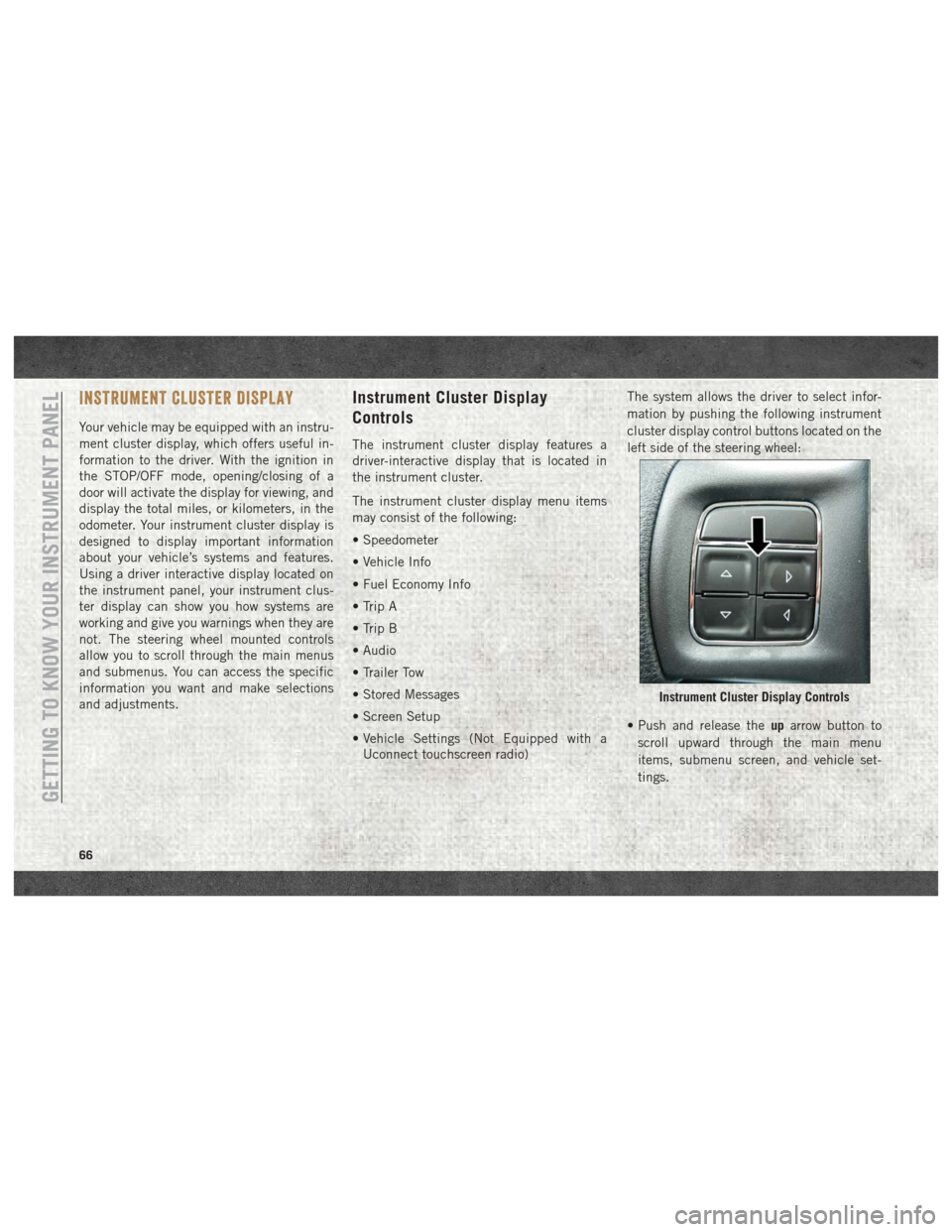
mation by pushing the following instrument
cluster display control buttons located on the
left side of the steering wheel:
• Push and release the
uparrow button to
scroll upward through the main menu
items, submenu screen, and vehicle set-
tings.
Instrument Cluster Display Controls
GETTING TO KNOW YOUR INSTRUMENT PANEL
66
Page 76 of 372
under demanding hot or high altitude condi-
tions. If the instrument cluster display dis-
plays the message “Active Airbox Service
Required See Dealer”, vehicle performance
may be reduced until service is performed by
an authorized RAM dealer.
Oil Life Reset
Your vehicle is equipped with an engine oil
change indicator system. The “Oil Change
Required” message will display in the instru-
ment cluster display after a single chime has
sounded, to indicate the next scheduled oil
change interval. The engine oil change indi-
cator system is duty cycle based, which
means the engine oil change interval may
fluctuate, dependent upon your personal
driving style.
NOTE:
Use the steering wheel instrument cluster
display controls for the following proce-
dure(s).Vehicles Equipped With Passive Entry
1. Without pushing the brake pedal, push
the ENGINE START/STOP button and
place the ignition to the ON/RUN position
(do not start the engine).
2. Push and release the downarrow button to
scroll downward through the main menu
to “Vehicle Info.”
3. Push and release the rightarrow button to
access the ”Vehicle Info” screen, then
scroll up or down to select “Oil Life.”
4. Push and hold the rightarrow button to
select “Reset”.
5. Push and release the downarrow button to
select “Yes,” then push and release the
right arrow button to select reset of the Oil
Life to 100%.
6. Push and release the uparrow button to
exit the instrument cluster display screen. Vehicles Not Equipped With Passive Entry
1. Without pushing the brake pedal, cycle
the ignition to the ON/RUN position (do
not start the engine).
2. Push and release the downarrow button to
scroll downward through the main menu
to “Vehicle Info.”
3. Push and release the rightarrow button to
access the “Vehicle Info” screen then
scroll up or down to select “Oil Life.”
4. Push and hold the rightarrow button to
select “YES” by pushing the rightarrow
then push and release the rightarrow
button to select reset of the Oil Life to
100%.
5. Push and release the uparrow button to
exit the instrument cluster display screen.
NOTE:
If the indicator message illuminates when
you start the vehicle, the Oil Life indicator
system did not reset. If necessary, repeat this
procedure.
GETTING TO KNOW YOUR INSTRUMENT PANEL
74
Page 77 of 372
Instrument Cluster Display Programmable Features
The instrument cluster display can be used to view or change the following settings. Push theupordown arrow button until System Setup
displays, then push the rightarrow button. Scroll through the settings using the upordown arrow button. Push the rightarrow button to change
the setting. Push the leftarrow button to scroll back to a previous menu or sub menu.
• Language Select • Remote Start Comfort System
• Units • Easy Exit Seat
• ParkSense • Key Off Power Delay
• Tilt Mirror In Reverse • Commercial Settings
• Rain Sensing Wipers • Air Suspension Display Alerts
• Hill Start Assist • Aero Ride Height Mode
• Headlights Off Delay • Tire/Jack Mode
• Illuminated Approach • Transport Mode
• Headlights On With Wipers • Wheel Alignment Mode
• Automatic Highbeams • Horn With Remote Lower
• Flash Lights With Lock • Lights With Remote Lower
• Auto Lock Doors • Trailer Select
• Auto Unlock Doors • Brake Type
• Sound Horn With Remote Start • Trailer Name
• Sound Horn With Remote Lock • Compass Variance
• Remote Unlock Sequence • Calibrate Compass
• Key Fob Linked To Memory • Fuel Saver Display
• Passive Entry • Park Assist Front Chime Volume
• Park Assist Rear Chime Volume
75
Page 82 of 372

Should one or more tires be in the condition
mentioned above, the display will show the
indications corresponding to each tire in
sequence.
CAUTION!
Do not continue driving with one or more
flat tires as handling may be compro-
mised. Stop the vehicle, avoiding sharp
braking and steering. If a tire puncture
occurs, repair immediately using the dedi-
cated tire repair kit and contact your au-
thorized dealer as soon as possible.
Each tire, including the spare (if provided),
should be checked monthly when cold and
inflated to the inflation pressure recom-
mended by the vehicle manufacturer on the
vehicle placard or tire inflation pressure la-
bel. (If your vehicle has tires of a different
size than the size indicated on the vehicle
placard or tire inflation pressure label, you
should determine the proper tire inflation
pressure for those tires.) As an added safety feature, your vehicle has
been equipped with a tire pressure monitor-
ing system (TPMS) that illuminates a low tire
pressure telltale when one or more of your
tires is significantly under-inflated. Accord-
ingly, when the low tire pressure telltale illu-
minates, you should stop and check your tires
as soon as possible, and inflate them to the
proper pressure. Driving on a significantly
under-inflated tire causes the tire to overheat
and can lead to tire failure. Under-inflation
also reduces fuel efficiency and tire tread
life, and may affect the vehicle’s handling
and stopping ability.
Please note that the TPMS is not a substitute
for proper tire maintenance, and it is the
driver’s responsibility to maintain correct tire
pressure, even if under-inflation has not
reached the level to trigger illumination of the
TPMS low tire pressure telltale.
Your vehicle has also been equipped with a
TPMS malfunction indicator to indicate when
the system is not operating properly. The
TPMS malfunction indicator is combined
with the low tire pressure telltale. When the
system detects a malfunction, the telltale will flash for approximately one minute and then
remain continuously illuminated. This se-
quence will continue upon subsequent ve-
hicle start-ups as long as the malfunction
exists. When the malfunction indicator is
illuminated, the system may not be able to
detect or signal low tire pressure as intended.
TPMS malfunctions may occur for a variety of
reasons, including the installation of replace-
ment or alternate tires or wheels on the ve-
hicle that prevent the TPMS from functioning
properly. Always check the TPMS malfunc-
tion telltale after replacing one or more tires
or wheels on your vehicle to ensure that the
replacement or alternate tires and wheels
allow the TPMS to continue to function
properly.
CAUTION!
The TPMS has been optimized for the
original equipment tires and wheels.
TPMS pressures and warning have been
established for the tire size equipped on
your vehicle. Undesirable system opera-
tion or sensor damage may result when
using replacement equipment that is not
GETTING TO KNOW YOUR INSTRUMENT PANEL
80
Page 83 of 372
CAUTION!
of the same size, type, and/or style. After-
market wheels can cause sensor damage.
Using aftermarket tire sealants may cause
the Tire Pressure Monitoring System
(TPMS) sensor to become inoperable. Af-
ter using an aftermarket tire sealant it is
recommended that you take your vehicle
to your authorized dealer to have your
sensor function checked.
— Low Fuel Indicator Light
When the fuel level reaches approximately
3.0 gal (11.0 L) this light will turn on, and
remain on until fuel is added.
— Anti-Lock Brake (ABS) Warning
Light
This light monitors the Anti-Lock Brake Sys-
tem (ABS). The light will turn on when the
ignition is placed in the ON/RUN or ACC/ON/
RUN position and may stay on for as long as
four seconds. If the ABS light remains on or turns on while
driving, then the Anti-Lock portion of the
brake system is not functioning and service is
required as soon as possible. However, the
conventional brake system will continue to
operate normally, assuming the Brake Warn-
ing Light is not also on.
If the ABS light does not turn on when the
ignition is placed in the ON/RUN or ACC/ON/
RUN position, have the brake system in-
spected by an authorized dealer.
— Low Coolant Level Warning Light
This telltale will turn on to indicate the ve-
hicle coolant level is low.
— Loose Fuel Filler Cap Warning Light
— If Equipped
This light will illuminate when the fuel filler
cap is loose. Properly close the filler cap to
disengage the light. If the light does not turn
off, please see your authorized dealer.
SERV4WD— Service 4WD Warning Light — If
Equipped
If the light stays on or comes on during driving,
it means that the 4WD system is not functioning
properly and that service is required. We recom-
mend you drive to the nearest service center and
have the vehicle serviced immediately.
— Transmission Temperature Warning
Light
This light indicates that the transmission
fluid temperature is running hot. This may
occur with severe usage, such as trailer tow-
ing. If this light turns on, safely pull over and
stop the vehicle. Then, shift the transmission
into PARK and run the engine at idle or
slightly higher until the light turns off.
WARNING!
If you continue operating the vehicle when
the Transmission Temperature Warning
Light is illuminated you could cause the
fluid to boil over, come in contact with hot
engine or exhaust components and cause a
fire.
81
Page 84 of 372
CAUTION!
Continuous driving with the Transmission
Temperature Warning Light illuminated
will eventually cause severe transmission
damage or transmission failure.
Yellow Indicator Lights
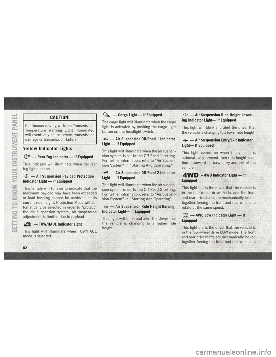
— Rear Fog Indicator — If Equipped
This indicator will illuminate when the rear
fog lights are on.
— Air Suspension Payload Protection
Indicator Light — If Equipped
This telltale will turn on to indicate that the
maximum payload may have been exceeded
or load leveling cannot be achieved at its
current ride height. Protection Mode will au-
tomatically be selected in order to “protect”
the air suspension system, air suspension
adjustment is limited due to payload.
— TOW/HAUL Indicator Light
This light will illuminate when TOW/HAUL
mode is selected.
— Cargo Light — If Equipped
The cargo light will illuminate when the cargo
light is activated by pushing the cargo light
button on the headlight switch.
— Air Suspension Off-Road 1 Indicator
Light — If Equipped
This light will illuminate when the air suspen-
sion system is set to the Off-Road 1 setting.
For further information, refer to “Air Suspen-
sion System” in “Starting And Operating.”
— Air Suspension Off-Road 2 Indicator
Light — If Equipped
This light will illuminate when the air suspen-
sion system is set to the Off-Road 2 setting.
For further information, refer to “Air Suspen-
sion System” in “Starting And Operating”.
— Air Suspension Ride Height Raising
Indicator Light— If Equipped
This light will blink and alert the driver that
the vehicle is changing to a higher ride
height.
— Air Suspension Ride Height Lower-
ing Indicator Light— If Equipped
This light will blink and alert the driver that
the vehicle is changing to a lower ride height.
— Air Suspension Entry/Exit Indicator
Light— If Equipped
This light comes on when the vehicle is
automatically lowered from ride height posi-
tion downward for easy entry and exit of the
vehicle.
– 4WD Indicator Light — If
Equipped
This light alerts the driver that the vehicle is
in the four-wheel drive mode, and the front
and rear driveshafts are mechanically locked
together forcing the front and rear wheels to
rotate at the same speed.
— 4WD Low Indicator Light — If
Equipped
This light alerts the driver that the vehicle is
in the four-wheel drive LOW mode. The front
and rear driveshafts are mechanically locked
together forcing the front and rear wheels toGETTING TO KNOW YOUR INSTRUMENT PANEL
82
Page 85 of 372

rotate at the same speed. Low range provides
a greater gear reduction ratio to provide in-
creased torque at the wheels.
Refer to “Four-Wheel Drive Operation — If
Equipped” in “Starting And Operating” for
further information on four-wheel drive op-
eration and proper use.
— Wait To Start Light — If Equipped
The “Wait To Start” telltale will illuminate for
approximately two seconds when the ignition
is turned to the RUN position. It’s duration
may be longer based on colder operating
conditions. Vehicle will not initiate start until
telltale is no longer displayed. Refer to
“Starting The Engine” in “Starting And Op-
erating” for further information.
NOTE:
The “Wait To Start” telltale may not illumi-
nate if the intake manifold temperature is
warm enough.
— Water In Fuel Indicator Light — If
Equipped
The “Water In Fuel Indicator Light” will illu-
minate when there is water detected in the
fuel filters. If this light remains on, DO NOT
start the vehicle before you drain the water
from the fuel filters to prevent engine dam-
age. Refer to the “Draining Fuel/Water Sepa-
rator Filter” section in “Dealer Service” in
“Servicing And Maintenance” for further in-
formation.
— Low Diesel Exhaust Fluid (DEF) Indi-
cator Light — If Equipped
The Low Diesel Exhaust Fluid (DEF) Indicator
will illuminate if the vehicle is low on Diesel
Exhaust Fluid (DEF). Refer to “Starting And
Operating” for further information.
Green Indicator Lights
— Park/Headlight On Indicator Light
This indicator will illuminate when the park
lights or headlights are turned on.
— Front Fog Indicator Light — If
Equipped
This indicator will illuminate when the front
fog lights are on.
— Turn Signal Indicator Lights
When the left or right turn signal is activated,
the turn signal indicator will flash indepen-
dently and the corresponding exterior turn
signal lamps will flash. Turn signals can be
activated when the multifunction lever is
moved down (left) or up (right).
NOTE:
• A continuous chime will sound if the ve- hicle is driven more than 1 mile (1.6 km)
with either turn signal on.
• Check for an inoperative outside light bulb if either indicator flashes at a rapid rate.
—Cruise Control Set Indicator Light —
If Equipped
This light will turn on when the speed control
is set to the desired speed. Refer to “Speed
Control” in “Starting And Operating” for fur-
ther information.
83
Page 86 of 372
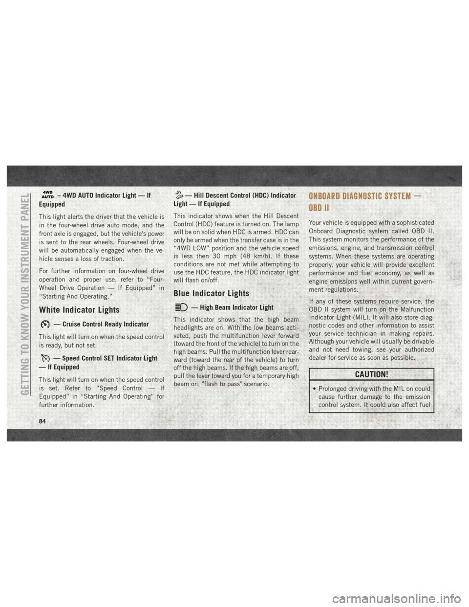
– 4WD AUTO Indicator Light — If
Equipped
This light alerts the driver that the vehicle is
in the four-wheel drive auto mode, and the
front axle is engaged, but the vehicle's power
is sent to the rear wheels. Four-wheel drive
will be automatically engaged when the ve-
hicle senses a loss of traction.
For further information on four-wheel drive
operation and proper use, refer to “Four-
Wheel Drive Operation — If Equipped” in
“Starting And Operating.”
White Indicator Lights
— Cruise Control Ready Indicator
This light will turn on when the speed control
is ready, but not set.
— Speed Control SET Indicator Light
— If Equipped
This light will turn on when the speed control
is set. Refer to “Speed Control — If
Equipped” in “Starting And Operating” for
further information.
— Hill Descent Control (HDC) Indicator
Light — If Equipped
This indicator shows when the Hill Descent
Control (HDC) feature is turned on. The lamp
will be on solid when HDC is armed. HDC can
only be armed when the transfer case is in the
“4WD LOW” position and the vehicle speed
is less then 30 mph (48 km/h). If these
conditions are not met while attempting to
use the HDC feature, the HDC indicator light
will flash on/off.
Blue Indicator Lights
— High Beam Indicator Light
This indicator shows that the high beam
headlights are on. With the low beams acti-
vated, push the multifunction lever forward
(toward the front of the vehicle) to turn on the
high beams. Pull the multifunction lever rear-
ward (toward the rear of the vehicle) to turn
off the high beams. If the high beams are off,
pull the lever toward you for a temporary high
beam on, "flash to pass" scenario.
ONBOARD DIAGNOSTIC SYSTEM —
OBD II
Your vehicle is equipped with a sophisticated
Onboard Diagnostic system called OBD II.
This system monitors the performance of the
emissions, engine, and transmission control
systems. When these systems are operating
properly, your vehicle will provide excellent
performance and fuel economy, as well as
engine emissions well within current govern-
ment regulations.
If any of these systems require service, the
OBD II system will turn on the Malfunction
Indicator Light (MIL). It will also store diag-
nostic codes and other information to assist
your service technician in making repairs.
Although your vehicle will usually be drivable
and not need towing, see your authorized
dealer for service as soon as possible.
CAUTION!
• Prolonged driving with the MIL on could
cause further damage to the emission
control system. It could also affect fuelGETTING TO KNOW YOUR INSTRUMENT PANEL
84