wheel Ram 2500 2018 Service Manual
[x] Cancel search | Manufacturer: RAM, Model Year: 2018, Model line: 2500, Model: Ram 2500 2018Pages: 372, PDF Size: 7.1 MB
Page 168 of 372

Four-Position Electronically
Shifted Transfer Case (Eight
Speed Transmission Only) — If
Equipped
This is an electronic shift transfer case and is
operated by the 4WD Control Switch (Trans-
fer Case Switch), which is located on the
instrument panel.This electronically shifted transfer case pro-
vides four mode positions:
• Two-Wheel Drive High Range (2WD)
• Four-Wheel Drive Lock High Range (4WD
LOCK)
• Four-Wheel Drive Low Range (4WD LOW)
• Neutral (NEUTRAL)
For additional information on the appropriate
use of each transfer case mode position, see
the information below:
2WD
Rear-Wheel Drive High Range — This range
is for normal street and highway driving on
dry hard surfaced roads.
4WD LOCK
Four-Wheel Drive Lock High Range — This
range maximizes torque to the front drive-
shaft, forcing the front and rear wheels to
rotate at the same speed. Additional traction
for loose, slippery road surfaces only.
Four-Position/On-Demand Transfer Case — Eight Speed Transmission Only
STARTING AND OPERATING
166
Page 169 of 372
4WD LOW
Four-Wheel Drive Low Range — This range
provides low speed four-wheel drive. It maxi-
mizes torque to the front driveshaft, forcing
the front and rear wheels to rotate at the same
speed. This range provides additional trac-
tion and maximum pulling power for loose,
slippery road surfaces only. Do not exceed
25 mph (40 km/h).
NEUTRAL (N)
Neutral — This range disengages both the
front and rear driveshafts from the pow-
ertrain. To be used for flat towing behind
another vehicle. Refer to “Recreational Tow-
ing” in this section for further information.
This electronically shifted transfer case is
designed to be driven in the two–wheel drive
position (2WD) for normal street and highway
conditions on dry hard surfaced roads). Driv-
ing the vehicle in 2WD will have greater fuel
economy benefits as the front axle is not
engaged in 2WD.When additional traction is required, the
transfer case 4WD LOCK and 4WD LOW po-
sitions can be used to maximize torque to the
front driveshaft, forcing the front and rear
wheels to rotate at the same speed. This is
accomplished by pushing the desired posi-
tion on the 4WD control switch.
Refer to “Shifting Procedure” in the “Start-
ing And Operating” section of your Owner’s
Manual for specific shifting instructions.
WARNING!
• You or others could be injured or killed if
you leave the vehicle unattended with
the transfer case in the NEUTRAL (N)
position without first fully engaging the
parking brake. The transfer case NEU-
TRAL (N) position disengages both the
front and rear drive shaft from the pow-
ertrain, and will allow the vehicle to roll,
even if the automatic transmission is in
PARK (or manual transmission is in
gear). The parking brake should always
be applied when the driver is not in the
vehicle.
WARNING!
• The transmission may not engage PARKif the vehicle is moving. Always bring the
vehicle to a complete stop before shift-
ing to PARK, and verify that the trans-
mission gear position indicator solidly
indicates PARK (P) without blinking. En-
sure that the vehicle is completely
stopped, and the PARK position is prop-
erly indicated, before exiting the ve-
hicle.
167
Page 170 of 372

Five-Position Electronically
Shifted Transfer Case (Eight
Speed Transmission Only) — If
Equipped
This is an electronic shift transfer case and is
operated by the 4WD Control Switch (Trans-
fer Case Switch), which is located on the
instrument panel.This electronically shifted transfer case pro-
vides five mode positions:
• Two-Wheel Drive High Range (2WD)
• Four-Wheel Drive Automatic High Range
(4WD AUTO)
• Four-Wheel Drive Lock High Range (4WD LOCK)
• Four-Wheel Drive Low Range (4WD LOW)
• Neutral (NEUTRAL)
For additional information on the appropriate
use of each transfer case mode position, see
the information below:
2WD
Rear-Wheel Drive High Range — This range
is for normal street and highway driving on
dry hard surfaced roads.
4WD AUTO
Four-Wheel Drive Auto High Range — This
range sends power to the front wheels. The
four–wheel drive system will be automatically
engaged when the vehicle senses a loss of
traction. Additional traction for varying road
conditions.
Five-Position/On-Demand Transfer Case — Eight Speed Transmission Only
STARTING AND OPERATING
168
Page 171 of 372
4WD LOCK
Four-Wheel Drive Lock High Range — This
range maximizes torque to the front drive-
shaft, forcing the front and rear wheels to
rotate at the same speed. Additional traction
for loose, slippery road surfaces only.
4WD LOW
Four-Wheel Drive Low Range — This range
provides low speed four-wheel drive. It maxi-
mizes torque to the front driveshaft, forcing
the front and rear wheels to rotate at the same
speed. This range provides additional trac-
tion and maximum pulling power for loose,
slippery road surfaces only. Do not exceed
25 mph (40 km/h).
NEUTRAL (N)
Neutral — This range disengages both the
front and rear driveshafts from the pow-
ertrain. To be used for flat towing behind
another vehicle. Refer to “Recreational Tow-
ing” in this section for further information.
This electronically shifted transfer case is
designed to be driven in the two–wheel drive
position (2WD) or four-wheel drive position
(4WD AUTO) for normal street and highwayconditions on dry hard surfaced roads). Driv-
ing the vehicle in 2WD will have greater fuel
economy benefits as the front axle is not
engaged in 2WD.
For variable driving conditions, the 4WD
AUTO mode can be used. In this mode, the
front axle is engaged, but the vehicle's power
is sent to the rear wheels. Four-wheel drive
will be automatically engaged when the ve-
hicle senses a loss of traction. Because the
front axle is engaged, this mode will result in
lower fuel economy than the 2WD mode.
When additional traction is required, the
transfer case 4WD LOCK and 4WD LOW po-
sitions can be used to maximize torque to the
front driveshaft, forcing the front and rear
wheels to rotate at the same speed. This is
accomplished pushing the desired position
on the 4WD Control Switch.
Refer to “Shifting Procedure” in the “Start-
ing And Operating” section of your Owner’s
Manual for further details.WARNING!
• You or others could be injured or killed if
you leave the vehicle unattended with
the transfer case in the NEUTRAL (N)
position without first fully engaging the
parking brake. The transfer case NEU-
TRAL (N) position disengages both the
front and rear drive shaft from the pow-
ertrain, and will allow the vehicle to roll,
even if the automatic transmission is in
PARK (or manual transmission is in
gear). The parking brake should always
be applied when the driver is not in the
vehicle.
• The transmission may not engage PARK
if the vehicle is moving. Always bring the
vehicle to a complete stop before shift-
ing to PARK, and verify that the trans-
mission gear position indicator solidly
indicates PARK (P) without blinking. En-
sure that the vehicle is completely
stopped, and the PARK position is prop-
erly indicated, before exiting the ve-
hicle.
169
Page 173 of 372
if the vehicle speed exceeds 66 mph
(106 km/h). The vehicle will return to NRH
from Aero Mode if the vehicle speed re-
mains between 30 mph (48 km/h) and
35 mph (56 km/h) for greater than 20 sec-
onds or if the vehicle speed falls below
30 mph (48 km/h).
NOTE:
Automatic Aero Mode may be disabled
through vehicle settings in the instrument
cluster when equipped with Uconnect 3.0, or
your Uconnect Radio when equipped with
Uconnect 5.0, 8.4A, or 8.4AN.
• Entry/Exit Mode (Lowers the vehicle approxi-
mately 2 in (51 mm)) - This position lowers
the vehicle for easier passenger entry and
exit as well as lowering the rear of the
vehicle for easier loading and unloading of
cargo. To enter Entry/Exit Mode, push the
“Down” button once from the NHR while
the vehicle speed is below 33 mph (53 km/
h). Once the vehicle speed goes below
15 mph (24 km/h) the vehicle height will
begin to lower. If the vehicle speed remains
between 15 mph (24 km/h) and 25 mph
(40 km/h) for greater than 60 seconds, or the vehicle speed exceeds 25 mph
(40 km/h) the Entry/Exit change will be
cancelled. To return to Normal Height
Mode, push the “Up” button once while in
Entry/Exit or drive the vehicle over 15 mph
(24 km/h). Entry/Exit mode may not be
available due to vehicle payload, an instru-
ment cluster message will be displayed
when this occurs. Refer to “Instrument
Cluster Display” in “Getting To Know Your
Instrument Panel” in the Owner’s Manual
for further information.
Air Suspension Modes
The Air Suspension system has multiple
modes to protect the system in unique situa-
tions:
AERO Mode
To improve aerodynamics, the air suspension
system has a feature which will put the ve-
hicle into AERO height automatically. Refer
to “Instrument Cluster Display” in “Getting
To Know Your Instrument Panel” in the Own-
er’s Manual for further information.
NOTE:
This mode is intended to be enabled with
engine running.
Tire/Jack Mode
To assist with changing a tire, the air suspen-
sion system has a feature which allows the
automatic leveling to be disabled. Refer to
“Instrument Cluster Display” in “Getting To
Know Your Instrument Panel” in the Owner’s
Manual for further information.
NOTE:
This mode is intended to be enabled with
engine running.
Transport Mode
For towing your vehicle with four wheels off
the ground, the air suspension system has a
feature which will put the vehicle into Entry/
Exit height and disable the automatic load
leveling system. Refer to “Instrument Cluster
Display” in “Getting To Know Your Instru-
ment Panel” in the Owner’s Manual for fur-
ther information.
171
Page 174 of 372
NOTE:
This mode is intended to be enabled with
engine running.
Wheel Alignment Mode
Before performing a wheel alignment, this
mode must be enabled. Refer to “Instrument
Cluster Display” in “Getting To Know Your
Instrument Panel” in the Owner’s Manual for
further information.
NOTE:
This mode is intended to be enabled with
engine running.
Protection Strategy
In order to “protect” the air suspension sys-
tem, the vehicle will disable load leveling as
required (suspension overloaded, battery
charge low, etc.). Load leveling will automati-
cally resume as soon as system operation
requirements are met. See your authorized
dealer if system does not resume.
NOTE:
If towing with air suspension refer to “Trailer
Towing” in “Starting And Operating” for fur-
ther information.AIR SUSPENSION SYSTEM (REBEL
MODELS ONLY) — IF EQUIPPED
Description
The air suspension system provides full time
load leveling capability along with the benefit
of being able to adjust vehicle height by the
push of a button.
Automatic height changes will occur based
on vehicle speed and the current vehicle
height. The indicator lamps and instrument
cluster messages will operate the same for
automatic changes and user requested
changes.NOTE:
The vehicle will automatically enter Aero Mode
when the vehicle speed remains between
62 mph (100 km/h) and 66 mph (106 km/h)
for greater than 20 seconds or if the vehicle
speed exceeds 66 mph (106 km/h).
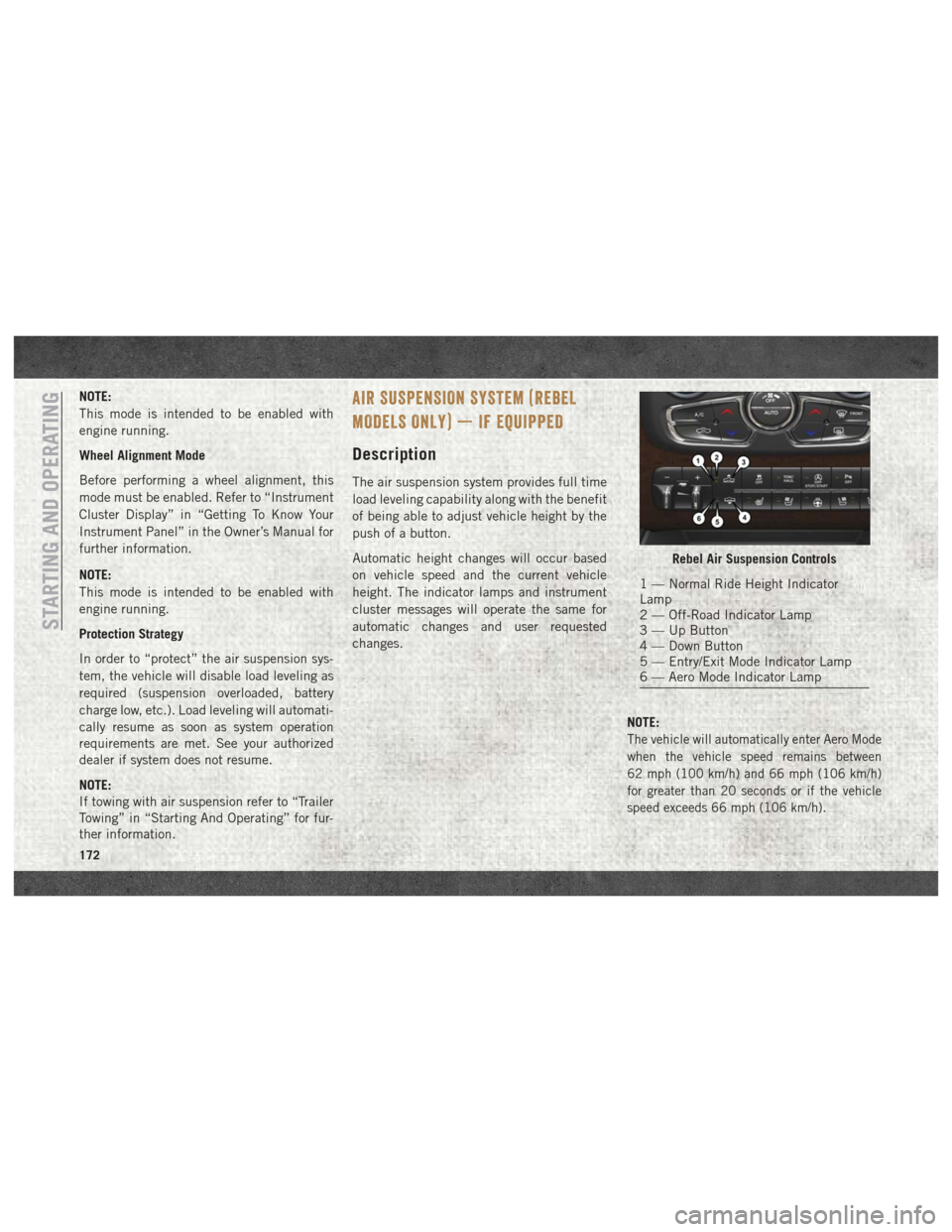
Rebel Air Suspension Controls
1 — Normal Ride Height Indicator
Lamp
2 — Off-Road Indicator Lamp
3 — Up Button
4 — Down Button
5 — Entry/Exit Mode Indicator Lamp
6 — Aero Mode Indicator Lamp
STARTING AND OPERATING
172
Page 176 of 372
to “Instrument Cluster Display” in “Getting
To Know Your Instrument Panel” in the Own-
er’s Manual for further information.
NOTE:
This mode is intended to be enabled with
engine running.
Tire/Jack Mode
To assist with changing a tire, the air suspen-
sion system has a feature which allows the
automatic leveling to be disabled. Refer to
“Instrument Cluster Display” in “Getting To
Know Your Instrument Panel” in the Owner’s
Manual for further information.
NOTE:
This mode is intended to be enabled with
engine running.
Transport Mode
For towing your vehicle with four wheels off
the ground, the air suspension system has a
feature which will put the vehicle into Entry/
Exit height and disable the automatic loadleveling system. Refer to “Instrument Cluster
Display” in “Getting To Know Your Instru-
ment Panel” in the Owner’s Manual for fur-
ther information.
NOTE:
This mode is intended to be enabled with
engine running.
Wheel Alignment Mode
Before performing a wheel alignment, this
mode must be enabled. Refer to “Instrument
Cluster Display” in “Getting To Know Your
Instrument Panel” in the Owner’s Manual for
further information.
NOTE:
This mode is intended to be enabled with
engine running.
Protection Strategy
In order to “protect” the air suspension sys-
tem, the vehicle will disable load leveling as
required (suspension overloaded, battery
charge low, etc.). Load leveling will automati-
cally resume as soon as system operation
requirements are met. See your authorized
dealer if system does not resume. NOTE:
If towing with air suspension refer to “Trailer
Towing” in “Starting And Operating” for fur-
ther information.
AIR SUSPENSION SYSTEM
(2500/3500 MODELS) — IF
EQUIPPED
Description
This air suspension system is a rear leveling
ride height system. The main purpose of this
system is to maintain the truck’s rear ride
height level. There are two selectable heights
that can be chosen based on your operating
conditions.
The system requires that the ignition be in
ON/RUN position or the engine running with
zero vehicle speed for all user requested
changes and load leveling.
STARTING AND OPERATING
174
Page 178 of 372
Transport Mode
To assist with flat bed towing, the air suspen-
sion system has a feature which will put the
vehicle below Normal Ride Height (NRH) and
disable the automatic load leveling system.
This mode is intended to be enabled with
engine running. Refer to “Instrument Cluster
Display” in “Getting To Know Your Instru-
ment Panel” or “Uconnect Settings” in “Mul-
timedia” if equipped with a touch screen
radio, in your Owner’s Manual for further
information.
NOTE:
This mode is intended to be enabled with
engine running.
Wheel Alignment Mode
Before performing a wheel alignment this
mode must be enabled. Refer to “Instrument
Cluster Display” in “Getting To Know Your
Instrument Panel” or “Uconnect Settings” in
“Multimedia” if equipped with a touch
screen radio, in your Owner’s Manual for
further information.NOTE:
This mode is intended to be enabled with
engine running.
Protection Strategy
In order to “protect” the air suspension sys-
tem, the vehicle will disable load leveling as
required (suspension overloaded, battery
charge low, etc.). Load leveling will automati-
cally resume as soon as system operation
requirements are met. See your authorized
dealer if system does not resume.
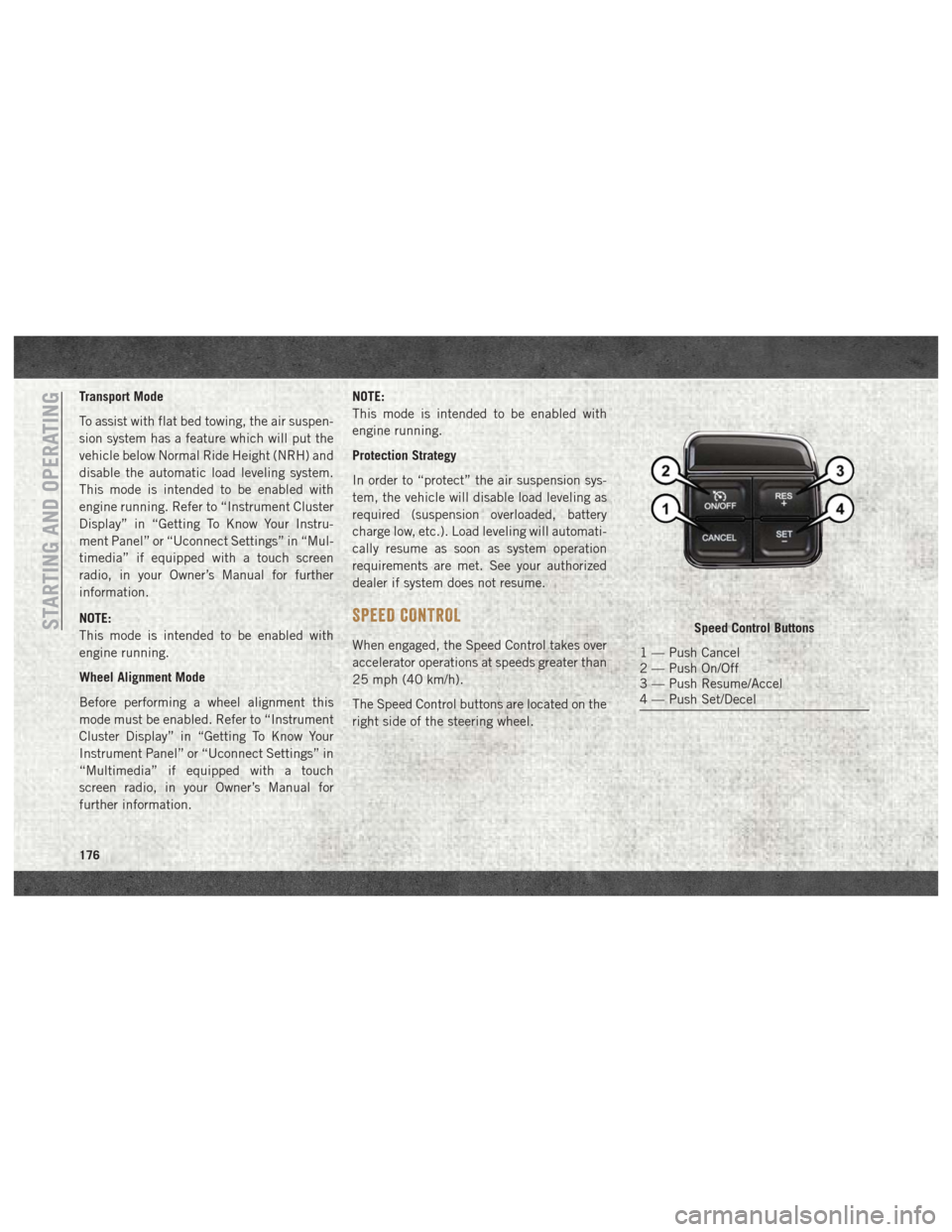
SPEED CONTROL
When engaged, the Speed Control takes over
accelerator operations at speeds greater than
25 mph (40 km/h).
The Speed Control buttons are located on the
right side of the steering wheel.
Speed Control Buttons
1 — Push Cancel
2 — Push On/Off
3 — Push Resume/Accel
4 — Push Set/Decel
STARTING AND OPERATING
176
Page 182 of 372

NOTE:
If the vehicle speed remains below 8 mph
(13 km/h), the Rear View Camera image will
be displayed continuously until deactivated
via the touchscreen button "X".
If equipped with a Cargo Camera, a touch-
screen button
to indicate the current
active Camera image being displayed is made
available whenever the Rear View Camera
image is displayed.
If equipped with a Cargo Camera, a touch-
screen button
to switch the display to
Cargo Camera image is made available when-
ever the Rear View Camera image is dis-
played.
A touchscreen button "X" to disable display of
the camera image is made available when the
vehicle is not in REVERSE gear.
When enabled, active guide lines are overlaid
on the image to illustrate the width of the
vehicle and its projected backup path based
on the steering wheel position. The active
guide lines will show separate zones that will
help indicate the distance to the rear of the
vehicle. NOTE:
For further information about how to access
and change the programmable features of the
ParkView Rear Backup Camera, refer to
“Uconnect Settings ” in “Multimedia” in the
Owner’s Manual for further information.
WARNING!
Drivers must be careful when backing up
even when using the ParkView Rear Back
Up Camera. Always check carefully behind
your vehicle, and be sure to check for
pedestrians, animals, other vehicles, ob-
structions, or blind spots before backing
up. You are responsible for the safety of
your surroundings and must continue to
pay attention while backing up. Failure to
do so can result in serious injury or death.
CAUTION!
• To avoid vehicle damage, ParkView
should only be used as a parking aid.
The ParkView camera is unable to view
every obstacle or object in your drive
path.
CAUTION!
• To avoid vehicle damage, the vehiclemust be driven slowly when using
ParkView to be able to stop in time when
an obstacle is seen. It is recommended
that the driver look frequently over his/
her shoulder when using ParkView.
NOTE:
If snow, ice, mud, or any foreign substance
builds up on the camera lens, clean the lens,
rinse with water, and dry with a soft cloth. Do
not cover the lens.
Turning Rear View Camera Image On:
1. Press the "Controls" button located on the bottom of the Uconnect display.
2. Press the "Backup Camera" button
to turn the Rear View Camera system on.
NOTE:
Once initiated by the "Backup Camera" but-
ton, the Rear View Camera image may be
deactivated by pressing the "X" button on the
touchscreen. On deactivation, the previous
selected screen will appear.
STARTING AND OPERATING
180
Page 193 of 372
TRAILER TOWING
Trailer Towing Weights (Maximum
Trailer Weight Ratings)
NOTE:
For trailer towing information (maximum
trailer weight ratings) refer to the following
website addresses:
•ramtrucks.com/en/towing_guide/
• ramtruck.ca (Canada)
• rambodybuilder.com
Towing Requirements
To promote proper break-in of your new ve-
hicle drivetrain components, the following
guidelines are recommended.
CAUTION!
• Do not tow a trailer at all during the first
500 miles (805 km) the new vehicle is
driven. The engine, axle or other parts
could be damaged.
CAUTION!
• Then, during the first 500 miles(805 km) that a trailer is towed, do not
drive over 50 mph (80 km/h) and do not
make starts at full throttle. This helps
the engine and other parts of the vehicle
wear in at the heavier loads.
Perform the maintenance listed in the
“Scheduled Servicing”. Refer to “Scheduled
Servicing” in “Servicing And Maintenance”
for the proper maintenance intervals. When
towing a trailer, never exceed the GAWR or
GCWR ratings.
WARNING!
Improper towing can lead to a collision.
Follow these guidelines to make your
trailer towing as safe as possible:
• Make certain that the load is secured in the trailer and will not shift during travel.
When trailering cargo that is not fully
secured, dynamic load shifts can occur
that may be difficult for the driver to
WARNING!
control. You could lose control of your
vehicle and have a collision.
• When hauling cargo or towing a trailer,
do not overload your vehicle or trailer.
Overloading can cause a loss of control,
poor performance or damage to brakes,
axle, engine, transmission, steering,
suspension, chassis structure or tires.
• Safety chains must always be used be-
tween your vehicle and trailer. Always
connect the chains to the hook retainers
of the vehicle hitch. Cross the chains
under the trailer tongue and allow
enough slack for turning corners.
• Vehicles with trailers should not be
parked on a grade. When parking, apply
the parking brake on the tow vehicle. Put
the tow vehicle transmission in PARK.
For four-wheel drive vehicles, make sure
the transfer case is not in NEUTRAL.
Always, block or "chock" the trailer
wheels.
• GCWR must not be exceeded.
191