climate settings Ram 2500 2020 Owner's Manual
[x] Cancel search | Manufacturer: RAM, Model Year: 2020, Model line: 2500, Model: Ram 2500 2020Pages: 553, PDF Size: 21.99 MB
Page 11 of 553

9
TECHNICAL SPECIFICATIONS
IDENTIFICATION DATA ...................................... 444Vehicle Identification Number ................. 444
BRAKE SYSTEM ................................................ 444
Hydraulic Brake Assist — If Equipped .......444
WHEEL AND TIRE TORQUE
SPECIFICATIONS ................................................ 444
Torque Specifications ................................444
FUEL REQUIREMENTS — GAS ENGINE ............ 446
6.4L Engine ................................................446
Reformulated Gasoline .............................446
Materials Added To Fuel ...........................446
Gasoline/Oxygenate Blends......................446
Do Not Use E-85 In Non-Flex Fuel
Vehicles ......................................................447 CNG And LP Fuel System Modifications ...447
MMT In Gasoline ........................................447
Fuel System Cautions ................................447
Carbon Monoxide Warnings ......................448
FUEL REQUIREMENTS – DIESEL ENGINE ...... 448
Fuel Specifications ...................................448
Biodiesel Fuel Requirements ....................449
FLUID CAPACITIES — GAS ENGINE .................. 451
FLUID CAPACITIES — DIESEL ENGINE............. 451
FLUIDS AND LUBRICANTS — GAS ENGINE ..... 452
Engine ........................................................ 452
Chassis .......................................................454 FLUIDS AND LUBRICANTS — DIESEL
ENGINE ................................................................ 454
Engine ........................................................ 454
Chassis ....................................................... 457
MULTIMEDIA
UCONNECT SYSTEMS .......................................458
CYBERSECURITY ............................................... 458
UCONNECT SETTINGS ........................................ 459
Uconnect 3 Settings .................................. 459
Uconnect 4/4C/4C NAV Settings ............. 473
Uconnect 4C NAV With 12-inch Display
Settings ...................................................... 493
SAFETY AND GENERAL INFORMATION ........... 511
Safety Guidelines....................................... 511
UCONNECT 3 WITH 5-INCH DISPLAY ..............512
Introduction................................................ 512
Radio Mode ................................................ 513
Media Mode ............................................... 516
Phone Mode ............................................... 518
STEERING WHEEL AUDIO CONTROLS — IF
EQUIPPED ...........................................................525
Radio Operation ......................................... 525
Media Mode ............................................... 525
IPOD®/USB/MP3 CONTROL —
IF EQUIPPED ....................................................... 525 RADIO OPERATION AND MOBILE PHONES.... 527
Regulatory And Safety Information .......... 527
VOICE RECOGNITION QUICK TIPS .................. 529
Introducing Uconnect ................................ 529
Get Started................................................. 529
Basic Voice Commands ............................ 529
Radio .......................................................... 530
Media ......................................................... 530
Phone ......................................................... 531
Voice Text Reply — If Equipped ................. 531
Climate (4C/4C NAV)................................. 532
Navigation (4C NAV) .................................. 532
Siri® Eyes Free — If Equipped ................. 532
Using Do Not Disturb ................................ 532
Android Auto™ — If Equipped .................. 533
Apple CarPlay® — If Equipped ................. 533
General Information .................................. 534
Additional Information............................... 534
CUSTOMER ASSISTANCE
SUGGESTIONS FOR OBTAINING SERVICE FOR
YOUR VEHICLE .................................................. 536
Prepare For The Appointment .................. 536
Prepare A List............................................. 536
Be Reasonable With Requests ................. 536
20_DJD2_OM_EN_USC_t.book Page 9
Page 39 of 553
GETTING TO KNOW YOUR VEHICLE37
Easy Entry/Exit Seat
This feature provides automatic driver’s seat
positioning to enhance driver mobility when
entering and exiting the vehicle.
The distance the driver’s seat moves depends
on where you have the driver’s seat positioned
when you place the ignition in the OFF position.
When you place the ignition in the OFF posi -
tion, the driver’s seat will move about
2.4 inches (60 mm) rearward if the driver’s
seat position is greater than or equal to
2.7 inches (67.7 mm) forward of the rear
stop. The seat will return to its previously set
position when you place the ignition into the
ACC or RUN position.
When you place the ignition in the OFF posi -
tion, the driver’s seat will move to a position
0.3 inches (7.7 mm) forward of the rear stop
if the driver’s seat position is between
0.9 inches and 2.7 inches (22.7 mm and
67.7 mm) forward of the rear stop. The seat
will return to its previously set position when
you place the ignition to the ACC or RUN posi -
tion.
The Easy Entry/Easy Exit feature is disabled
when the driver’s seat position is less than
0.9 inches (22.7 mm) forward of the rear stop. At this position, there is no benefit to
the driver by moving the seat for Easy Exit or
Easy Entry.
Each stored memory setting will have an associ -
ated Easy Entry and Easy Exit position.
NOTE:
The Easy Entry/Exit feature is not enabled when
the vehicle is delivered from the factory. The
Easy Entry/Exit feature is enabled (or later
disabled) through the programmable features
in the Uconnect system. Refer to “Uconnect
Settings” in “Multimedia” for further informa -
tion.
Heated Seats — If Equipped
On some models, the front and rear seats may
be equipped with heaters located in the seat
cushions and seat backs.Front Heated Seats
The heated seats control buttons are located on
the center instrument panel below the touch -
screen, and are also located within the climate
or controls screen of the touchscreen.
WARNING!
Persons who are unable to feel pain to the
skin because of advanced age, chronic
illness, diabetes, spinal cord injury, medica -
tion, alcohol use, exhaustion or other phys -
ical condition must exercise care when
using the seat heater. It may cause burns
even at low temperatures, especially if
used for long periods of time.
Do not place anything on the seat or seat -
back that insulates against heat, such as a
blanket or cushion. This may cause the seat
heater to overheat. Sitting in a seat that has
been overheated could cause serious
burns due to the increased surface
temperature of the seat.
2
20_DJD2_OM_EN_USC_t.book Page 37
Page 41 of 553
GETTING TO KNOW YOUR VEHICLE39
Ventilated Seats — If Equipped
Front Ventilated Seats
Located in the seat cushion are small fans that
draw the air from the passenger compartment
and move air through fine perforations in the
seat cover to help keep the driver and front
passenger cooler in higher ambient tempera -
tures. The fans operate at three speeds, HI,
MED and LO.
The front ventilated seats control buttons are
located on the center instrument panel below
the touchscreen, and are also located within the
climate or controls screen of the touchscreen.
NOTE:
If the vehicle is equipped with a 12-inch radio,
there will only be control buttons through the
touchscreen.
Press the ventilated seat button once to
choose HI.
Press the ventilated seat button a second
time to choose MED.
Press the ventilated seat button a third
time to choose LO.
Press the ventilated seat button a fourth
time to turn the ventilation off.
NOTE:
The engine must be running for the ventilated
seats to operate.
Vehicles Equipped With Remote Start
On models that are equipped with remote start,
the driver’s seat can be programmed to come
on during a remote start.
This feature can be programmed through the
Uconnect system. Refer to “Uconnect Settings”
in “Multimedia” for further information.
HEAD RESTRAINTS
Head restraints are designed to reduce the risk
of injury by restricting head movement in the
event of a rear impact. Head restraints should
be adjusted so that the top of the head restraint
is located above the top of your ear. NOTE:
Do not reverse the head restraints (making the
rear of the head restraint face forward) in an
attempt to gain additional clearance to the back
of your head.
WARNING!
All occupants, including the driver, should
not operate a vehicle or sit in a vehicle’s
seat until the head restraints are placed in
their proper positions in order to minimize
the risk of neck injury in the event of a
crash.
Head restraints should never be adjusted
while the vehicle is in motion. Driving a
vehicle with the head restraints improperly
adjusted or removed could cause serious
injury or death in the event of a collision.
2
20_DJD2_OM_EN_USC_t.book Page 39
Page 44 of 553
42GETTING TO KNOW YOUR VEHICLE
Pull the lever toward the steering wheel to
unlock the steering column. With one hand
firmly on the steering wheel, move the steering
column up or down, as desired. Release the
lever to lock the steering column firmly in place.
Tilt Steering Lever
Heated Steering Wheel — If Equipped
The steering wheel contains a heating element
that helps warm your hands in cold weather.
The heated steering wheel has only one
temperature setting. Once the heated steering
wheel has been turned on, it will stay on until
the operator turns it off. The heated steering
wheel may not turn on when it is already warm.
The heated steering wheel control button is
located on the center instrument panel below
the touchscreen, as well as within the climate or
controls screen of the touchscreen.
Press the heated steering wheel button
once to turn the heating element on.
Press the heated steering wheel button a
second time to turn the heating element off.
NOTE:
The engine must be running for the heated
steering wheel to operate.
Vehicles Equipped With Remote Start
On models that are equipped with remote start,
the heated steering wheel can be programmed
to come on during a remote start. This feature can be programmed through the
Uconnect system. Refer to “Uconnect Settings”
in “Multimedia” for further information.
WARNING!
Do not adjust the steering column while
driving. Adjusting the steering column while
driving or driving with the steering column
unlocked, could cause the driver to lose
control of the vehicle. Failure to follow this
warning may result in serious injury or death.
WARNING!
Persons who are unable to feel pain to the
skin because of advanced age, chronic
illness, diabetes, spinal cord injury, medica
-
tion, alcohol use, exhaustion, or other phys -
ical conditions must exercise care when
using the steering wheel heater. It may
cause burns even at low temperatures,
especially if used for long periods.
Do not place anything on the steering wheel
that insulates against heat, such as a
blanket or steering wheel covers of any type
and material. This may cause the steering
wheel heater to overheat.
20_DJD2_OM_EN_USC_t.book Page 42
Page 49 of 553
GETTING TO KNOW YOUR VEHICLE47
NOTE:
Fold the trailer towing mirrors rearward prior to
entering an automated car wash.
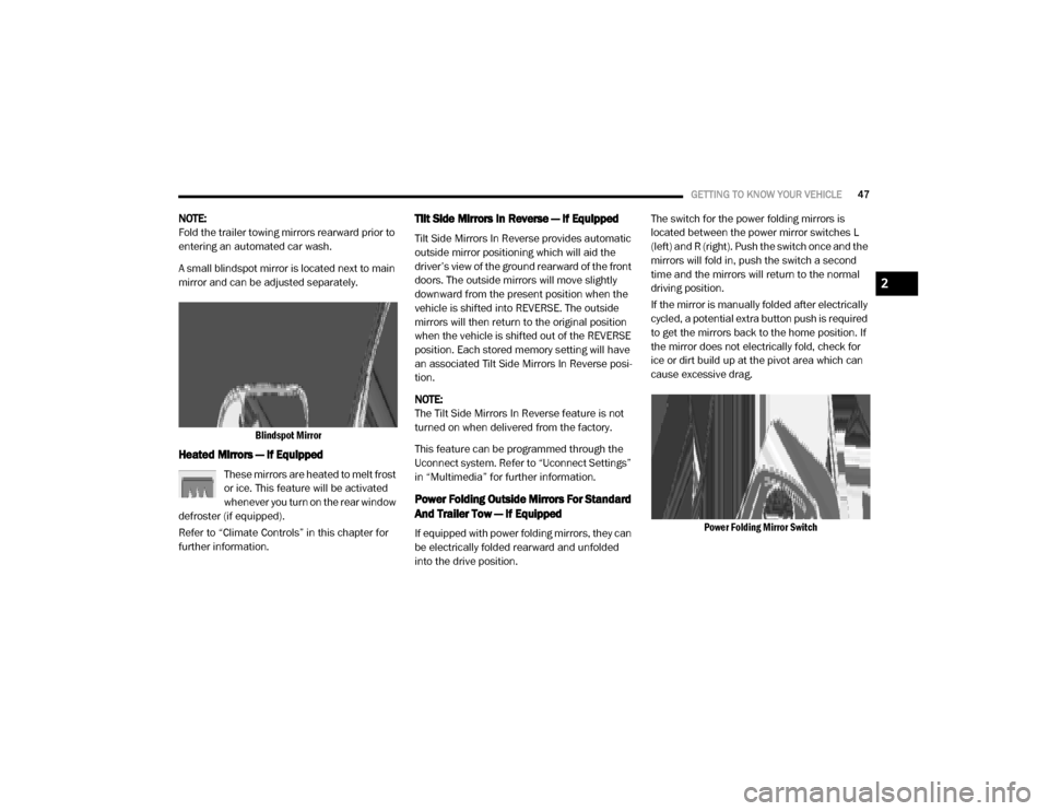
A small blindspot mirror is located next to main
mirror and can be adjusted separately.
Blindspot Mirror
Heated Mirrors — If Equipped
These mirrors are heated to melt frost
or ice. This feature will be activated
whenever you turn on the rear window
defroster (if equipped).
Refer to “Climate Controls” in this chapter for
further information.
Tilt Side Mirrors In Reverse — If Equipped
Tilt Side Mirrors In Reverse provides automatic
outside mirror positioning which will aid the
driver’s view of the ground rearward of the front
doors. The outside mirrors will move slightly
downward from the present position when the
vehicle is shifted into REVERSE. The outside
mirrors will then return to the original position
when the vehicle is shifted out of the REVERSE
position. Each stored memory setting will have
an associated Tilt Side Mirrors In Reverse posi -
tion.
NOTE:
The Tilt Side Mirrors In Reverse feature is not
turned on when delivered from the factory.
This feature can be programmed through the
Uconnect system. Refer to “Uconnect Settings”
in “Multimedia” for further information.
Power Folding Outside Mirrors For Standard
And Trailer Tow — If Equipped
If equipped with power folding mirrors, they can
be electrically folded rearward and unfolded
into the drive position. The switch for the power folding mirrors is
located between the power mirror switches L
(left) and R (right). Push the switch once and the
mirrors will fold in, push the switch a second
time and the mirrors will return to the normal
driving position.
If the mirror is manually folded after electrically
cycled, a potential extra button push is required
to get the mirrors back to the home position. If
the mirror does not electrically fold, check for
ice or dirt build up at the pivot area which can
cause excessive drag.
Power Folding Mirror Switch
2
20_DJD2_OM_EN_USC_t.book Page 47
Page 58 of 553

56GETTING TO KNOW YOUR VEHICLE
Windshield Washers
To use the windshield washer, push the washer
knob, located on the end of the multifunction
lever, inward to the second detent. Washer fluid
will be sprayed and the wiper will operate for
two to three cycles after the washer knob is
released from this position.
If the washer knob is depressed while in the
delay range, the wiper will operate for several
seconds after the washer knob is released. It
will then resume the intermittent interval previ -
ously selected. If the washer knob is pushed
while in the off position, the wiper will turn on
and cycle approximately three times after the
wash knob is released.
To prevent freeze-up of your windshield washer
system in cold weather, select a solution or
mixture that meets or exceeds the temperature
range of your climate. This rating information
can be found on most washer fluid containers.
Mist Feature
When a single wipe to clear off road mist or
spray from a passing vehicle is needed, push
the washer knob, located on the end of the
multifunction lever, inward to the first detent
and release. The wipers will cycle one time and
automatically shut off.
NOTE:
The mist feature does not activate the washer
pump; therefore, no washer fluid will be sprayed
on the windshield. The wash function must be
used in order to spray the windshield with
washer fluid.
Rain Sensing Wipers — If Equipped
This feature senses moisture on the windshield
and automatically activates the wipers for the
driver. The feature is especially useful for road
splash or overspray from the windshield
washers of the vehicle ahead. Rotate the end of
the multifunction lever to one of five settings to
activate this feature.
NOTE:
This feature can be programmed on/off through
the Uconnect system. Refer to “Uconnect
Settings” in “Multimedia” for further informa -
tion.
The sensitivity of the system can be adjusted
with the multifunction lever. Wiper delay posi -
tion 1 is the least sensitive, and wiper delay
position 5 is the most sensitive. Position 3
should be used for normal rain conditions. Posi -
tions 1 and 2 can be used if the driver desires
less wiper sensitivity. Positions 4 and 5 can be
used if the driver desires more sensitivity. Place
the wiper switch in the O (off) position when not
using the system.WARNING!
Sudden loss of visibility through the
windshield could lead to a collision. You might
not see other vehicles or other obstacles. To
avoid sudden icing of the windshield during
freezing weather, warm the windshield with
the defroster before and during windshield
washer use.
20_DJD2_OM_EN_USC_t.book Page 56
Page 62 of 553

60GETTING TO KNOW YOUR VEHICLE
Front Defrost Setting
Turn the Mode Control knob to the Front Defrost mode setting. Air comes from the windshield and side window demist
outlets. When the defrost button is selected, the blower level may increase. Use Defrost mode with maximum temperature
settings for best windshield and side window defrosting and defogging.
Rear Defrost Button
Push and release the Rear Defrost button to turn on the rear window defroster and the heated outside mirrors (if
equipped). The Rear Defrost indicator illuminates when the rear window defroster is on. The rear window defroster
automatically turns off after 15 minutes.
Climate Control OFF
To turn the Climate Controls off, turn the Blower Control knob to the O (off) position.
Icon Description
20_DJD2_OM_EN_USC_t.book Page 60
Page 66 of 553

64GETTING TO KNOW YOUR VEHICLE
Faceplate Auto Button
Touchscreen Auto Button AUTO
Press and release this button on the touchscreen, or push the button on the faceplate, to change the current setting. The
AUTO indicator illuminates when AUTO is on. This feature automatically controls the interior cabin temperature by adjusting
airflow distribution and amount. Toggling this function will cause the system to switch between manual mode and
automatic modes. Refer to “Automatic Operation” within this section for more information.
Front Defrost Button
Press and release the Front Defrost button on the touchscreen, or push and release the button on the faceplate, to change
the current airflow setting to Defrost mode. The Front Defrost indicator illuminates when Front Defrost is on. Air comes from
the windshield and side window demist outlets. When the defrost button is selected, the blower level may increase. Use
Defrost mode with maximum temperature settings for best windshield and side window defrosting and defogging. When
toggling the front defrost mode button, the climate system will return to previous setting.
Rear Defrost Button
Push and release the Rear Defrost button on the touchscreen, or push and release the button on the faceplate, to turn on
the rear window defroster and the heated outside mirrors (if equipped). The Rear Defrost indicator illuminates when the
rear window defroster is on. The rear window defroster automatically turns off after 15 minutes.
Icon
Description
20_DJD2_OM_EN_USC_t.book Page 64
Page 67 of 553
GETTING TO KNOW YOUR VEHICLE65
Faceplate Temperature
Knobs
Touchscreen
Temperature Buttons Driver and Passenger Temperature Up and Down Buttons
Provides the driver and passenger with independent temperature control. Push the red button (or rotate knob if equipped)
on the faceplate or touchscreen, or press and slide the temperature bar towards the red arrow button on the touchscreen
for warmer temperature settings. Push the blue button (or rotate knob if equipped) on the faceplate or touchscreen, or
press and slide the temperature bar towards the blue arrow button on the touchscreen for cooler temperature settings.
NOTE:
The numbers within the temperature display will only appear if the system is equipped with an automatic climate control
system.
Up and down buttons are only available on vehicles equipped with a 12-inch display.
SYNC
Press the SYNC button on the touchscreen to toggle the SYNC feature on/off. The SYNC indicator illuminates when SYNC is
on. SYNC synchronizes the passenger temperature setting with the driver temperature setting. Changing the passenger’s
temperature setting while in SYNC will automatically exit this feature.
NOTE:
The SYNC button is only available on the touchscreen.
Icon Description
2
20_DJD2_OM_EN_USC_t.book Page 65
Page 68 of 553
66GETTING TO KNOW YOUR VEHICLE
Faceplate Blower Knob
Touchscreen Blower Buttons Blower Control
Blower Control regulates the amount of air forced through the climate system. There are seven blower speeds available.
The speeds can be selected using either the blower control knob on the faceplate or the buttons on the touchscreen.
Faceplate: The blower speed increases as you turn the blower control knob clockwise from the lowest blower setting. The
blower speed decreases as you turn the blower control knob counterclockwise.
Touchscreen:
Use the small blower icon to reduce the blower setting and the large blower icon to increase the blower
setting. Blower can also be selected by pressing the blower bar area between the icons.
NOTE:
On Uconnect 4C NAV With 12–inch display radios, pressing the blower control button below one turns the Climate Control
system OFF.
Faceplate Mode Button
Touchscreen Mode Buttons Mode Control
Mode Control regulates the airflow distribution. The airflow distribution outlets are: instrument panel outlets, floor outlets,
defrost outlets, and demist outlets. Faceplate: Push the Mode Button to change the airflow distribution mode.
Touchscreen: Press one of the “MODE” buttons to change the airflow distribution mode.
The Mode settings are as follows:
Icon
Description
20_DJD2_OM_EN_USC_t.book Page 66