power steering Ram 2500 2020 Owner's Manual
[x] Cancel search | Manufacturer: RAM, Model Year: 2020, Model line: 2500, Model: Ram 2500 2020Pages: 553, PDF Size: 21.99 MB
Page 4 of 553

2
INTRODUCTION
HOW TO USE THIS MANUAL ...............................12
Essential Information .................................. 12
Symbols ........................................................ 12
WARNINGS AND CAUTIONS ...............................12
VAN CONVERSIONS/CAMPERS ..........................12
VEHICLE MODIFICATIONS/ALTERATIONS .........12
GETTING TO KNOW YOUR VEHICLE
VEHICLE USER GUIDE — IF EQUIPPED ...............13
KEYS ......................................................................14
Key Fob......................................................... 14
IGNITION SWITCH .................................................18
Keyless Push Button Ignition ...................... 18
REMOTE START — IF EQUIPPED (GASOLINE) ..20
How To Use Remote Start ........................... 20
Remote Start Abort Message ...................... 20
To Enter Remote Start Mode ...................... 20
To Exit Remote Start Mode Without Driving
The Vehicle .................................................. 21 To Exit Remote Start Mode And Drive The
Vehicle .......................................................... 21 Remote Start Comfort Systems —
If Equipped ................................................... 21 General Information .................................... 21 REMOTE START— IF EQUIPPED (DIESEL).......... 22
How To Use Remote Start ........................... 22
Remote Start Abort Message...................... 23
To Enter Remote Start Mode ...................... 23
To Exit Remote Start Mode Without Driving
The Vehicle ................................................... 23 To Exit Remote Start Mode And Drive The
Vehicle .......................................................... 23 Remote Start Comfort Systems —
If Equipped ................................................... 24
SENTRY KEY.......................................................... 24
Key Programming ....................................... 24
Replacement Keys....................................... 24
General Information .................................... 25
VEHICLE SECURITY ALARM ................................ 25
To Arm The System ...................................... 25
To Disarm The System ................................ 26
Rearming Of The System............................. 26
Security System Manual Override .............. 26
DOORS .................................................................. 27
Manual Door Locks...................................... 27
Power Door Locks — If Equipped ............... 27
Power Side Steps — If Equipped ................. 28
Keyless Enter-N-Go — Passive Entry .......... 28
Automatic Door Locks — If Equipped ......... 31
Child-Protection Door Lock ........................ 31 SEATS ....................................................................32
Manual Front Seat Adjustment .................. 32
Manual Rear Seat Adjustment ................... 33
Power Driver Seat Adjustment —
If Equipped ................................................... 34 Driver Memory Seats — If Equipped ........... 35
Heated Seats — If Equipped ....................... 37
Ventilated Seats — If Equipped................... 39
HEAD RESTRAINTS ..............................................39
Front Head Restraints ................................. 40
Rear Head Restraint Adjustment ............... 41
Rear Head Restraint Removal .................... 41
STEERING WHEEL.................................................41
Tilt Steering Column .................................... 41
Heated Steering Wheel — If Equipped ...... 42
DRIVER ADJUSTABLE PEDALS —
IF EQUIPPED .........................................................43
MIRRORS ..............................................................43
Inside Day/Night Mirror — If Equipped ...... 43
Automatic Dimming Mirror — If
Equipped ..................................................... 44 Automatic Dimming Mirror With Rear View
Camera Display — If Equipped ................... 44 Outside Mirrors ........................................... 45
Driver's Outside Automatic Dimming Mirror — If
Equipped ...................................................... 45
20_DJD2_OM_EN_USC_t.book Page 2
Page 23 of 553

GETTING TO KNOW YOUR VEHICLE21
NOTE:
If your power door locks were unlocked,
Remote Start will automatically lock the
doors.
If an engine fault is present or fuel level is
low, the vehicle will start and then shut down
in 10 seconds.
The park lamps will turn on and remain on
during Remote Start mode.
For security, power window and power
sunroof operation (if equipped) are disabled
when the vehicle is in the Remote Start
mode.
The engine can be started two consecutive
times (two 15 minute cycles) with the key
fob. However, the ignition must be placed in
the ON/RUN position before you can repeat
the start sequence for a third cycle.
To Exit Remote Start Mode Without Driving
The Vehicle
Push and release the remote start button one
time or allow the engine to run for the entire
15 minute cycle. NOTE:
To avoid unintentional shutdowns, the system
will disable for two seconds after receiving a
valid Remote Start request
To Exit Remote Start Mode And Drive The
Vehicle
Before the end of the 15 minute cycle, push and
release the unlock button on the key fob to
unlock the doors and disarm the vehicle secu-
rity alarm system (if equipped). Then, prior to
the end of the 15 minute cycle, place the igni
-
tion in the ON/RUN position.
Remote Start Comfort Systems — If
Equipped
When remote start is activated, the heated
steering wheel, and driver heated seat features
will automatically turn on in cold weather. In
warm weather, the driver vented seat feature
will automatically turn on when the remote start
is activated. These features will stay on through
the duration of remote start or until the ignition
switch is placed in the ON/RUN position. NOTE:
The Remote Start Comfort system can be acti
-
vated and deactivated through the Uconnect
System under “Auto-On Comfort And Remote
Start”. Refer to “Uconnect Settings” in “Multi -
media” for further information on Remote Start
Comfort System operation.
General Information
The following regulatory statement applies to all
Radio Frequency (RF) devices equipped in this
vehicle:
This device complies with Part 15 of the FCC
Rules and with Innovation, Science and
Economic Development Canada license-exempt
RSS standard(s). Operation is subject to the
following two conditions:
1. This device may not cause harmful interfer -
ence, and
2. This device must accept any interference received, including interference that may
cause undesired operation.
2
20_DJD2_OM_EN_USC_t.book Page 21
Page 76 of 553
74GETTING TO KNOW YOUR VEHICLE
Sunshade Operation
The sunshade can be opened manually.
However, the sunshade will open automatically
as the sunroof opens.
NOTE:
The sunshade cannot be closed if the sunroof is
open.
Pinch Protect Feature
This feature will detect an obstruction in the
closing of the sunroof during the Express Close
operation. If an obstruction in the path of the
sunroof is detected, the sunroof will automati-
cally retract. Remove the obstruction if this
occurs.
NOTE:
If three consecutive sunroof close attempts
result in Pinch Protect reversals, Pinch Protect
will disable and the sunroof must be closed in
Manual Mode.
Venting Sunroof — Express
Push and release the Vent button within one
half second and the sunroof will open to the
vent position. This is called “Express Vent”, and
it will occur regardless of sunroof position. During Express Vent operation, any other actua-
tion of the switch will stop the sunroof.
Sunroof Maintenance
Use only a non-abrasive cleaner and a soft cloth
to clean the glass panel.
Ignition Off Operation
The power sunroof switch will remain active for
up to approximately 10 minutes after the igni
-
tion switch is placed in the OFF position.
Opening either front door will cancel this
feature.
NOTE:
Ignition Off time is programmable through the
Uconnect System. Refer to “Uconnect Settings”
in “Multimedia” for further information.
HOOD
To Open The Hood
To open the hood, two latches must be
released.
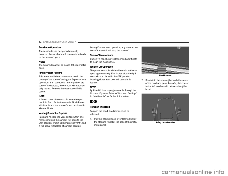
1. Pull the hood release lever located below the steering wheel at the base of the instru -
ment panel.
Hood Release
2. Reach into the opening beneath the center of the hood and push the safety latch lever
to the left to release it, before raising the
hood.
Safety Latch Location
20_DJD2_OM_EN_USC_t.book Page 74
Page 92 of 553
90GETTING TO KNOW YOUR VEHICLE
Power Inverter — If Equipped
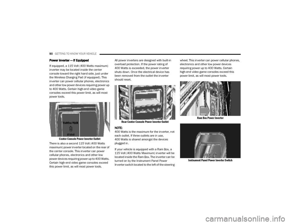
If equipped, a 115 Volt (400 Watts maximum)
inverter may be located inside the center
console toward the right hand side, just under
the Wireless Charging Pad (if equipped). This
inverter can power cellular phones, electronics
and other low power devices requiring power up
to 400 Watts. Certain high-end video game
consoles exceed this power limit, as will most
power tools.
Center Console Power Inverter Outlet
There is also a second 115 Volt (400 Watts
maximum) power inverter located on the rear of
the center console. This inverter can power
cellular phones, electronics and other low
power devices requiring power up to 400 Watts.
Certain high-end video game consoles exceed
this power limit, as will most power tools. All power inverters are designed with built-in
overload protection. If the power rating of
400 Watts is exceeded, the power inverter
shuts down. Once the electrical device has
been removed from the outlet the inverter
should reset.
Rear Center Console Power Inverter Outlet
NOTE:
400 Watts is the maximum for the inverter, not
each outlet. If three outlets are in use,
400 Watts is shared amongst the devices
plugged in.
If your vehicle is equipped with a Ram Box, a
115 Volt (400 Watts Maximum) inverter will be
located inside the Ram Box. The inverter can be
turned on by the Instrument Panel Power
Inverter switch located to the left of the steering wheel. This inverter can power cellular phones,
electronics and other low power devices
requiring power up to 400 Watts. Certain
high-end video game consoles exceed this
power limit, as will most power tools.
Ram Box Power Inverter
Instrument Panel Power Inverter Switch
20_DJD2_OM_EN_USC_t.book Page 90
Page 136 of 553
134GETTING TO KNOW YOUR INSTRUMENT PANEL
Electronic Stability Control (ESC) Active
Warning Light — If Equipped
This warning light will indicate when
the Electronic Stability Control system
is Active. The “ESC Indicator Light” in
the instrument cluster will come on
when the ignition is placed in the ON/RUN or ACC/ON/RUN position, and when ESC is acti
-
vated. It should go out with the engine running.
If the “ESC Indicator Light” comes on continu -
ously with the engine running, a malfunction
has been detected in the ESC system. If this
warning light remains on after several ignition
cycles, and the vehicle has been driven several
miles (kilometers) at speeds greater than
30 mph (48 km/h), see an authorized dealer as
soon as possible to have the problem diag -
nosed and corrected.
The “ESC OFF Indicator Light” and the “ESC
Indicator Light” come on momentarily each
time the ignition is placed in the ON/RUN or
ACC/ON/RUN position.
The ESC system will make buzzing or clicking
sounds when it is active. This is normal; the
sounds will stop when ESC becomes inactive.
This light will come on when the vehicle is in
an ESC event.
Electronic Stability Control (ESC) OFF
Warning Light — If Equipped
This warning light indicates the Elec -
tronic Stability Control (ESC) is off.
Each time the ignition is turned to ON/
RUN or ACC/ON/RUN, the ESC system
will be on, even if it was turned off previously.
LaneSense Warning Light — If Equipped
The LaneSense system provides the
driver with visual and steering torque
warnings when the vehicle starts to
drift out of its lane unintentionally
without the use of a turn signal.
When the LaneSense system senses a lane
drift situation, the LaneSense indicator
changes from solid green to solid yellow.
When the LaneSense system senses the lane
has been approached and is in a lane depar -
ture situation, the LaneSense indicator
changes from solid white/green to flashing
yellow.
Refer to “LaneSense – If Equipped” in
“Starting And Operating” for further informa -
tion.
WARNING!
A malfunctioning catalytic converter, as
referenced above, can reach higher
temperatures than in normal operating
conditions. This can cause a fire if you drive
slowly or park over flammable substances
such as dry plants, wood, cardboard, etc. This
could result in death or serious injury to the
driver, occupants or others.
CAUTION!
Prolonged driving with the Malfunction
Indicator Light (MIL) on could cause damage
to the vehicle control system. It also could
affect fuel economy and driveability. If the
MIL is flashing, severe catalytic converter
damage and power loss will soon occur.
Immediate service is required.
20_DJD2_OM_EN_USC_t.book Page 134
Page 148 of 553

146SAFETY
(Continued)
Electronic Brake Force Distribution (EBD)
This function manages the distribution of the
braking torque between the front and rear axles
by limiting braking pressure to the rear axle.
This is done to prevent overslip of the rear
wheels to avoid vehicle instability, and to
prevent the rear axle from entering Anti-Lock
Brake System (ABS) before the front axle.
Electronic Stability Control (ESC)
This system enhances directional control and
stability of the vehicle under various driving
conditions. Electronic Stability Control (ESC)
corrects for oversteering or understeering of the
vehicle by applying the brake of the appropriate
wheel(s) to assist in counteracting the oversteer
or understeer condition. Engine power may also
be reduced to help the vehicle maintain the
desired path.
ESC uses sensors in the vehicle to determine
the vehicle path intended by the driver and
compares it to the actual path of the vehicle.
When the actual path does not match the
intended path, ESC applies the brake of the
appropriate wheel to assist in counteracting the
oversteer or understeer condition.
Oversteer — when the vehicle is turning more
than appropriate for the steering wheel posi-
tion.
Understeer — when the vehicle is turning less
than appropriate for the steering wheel posi -
tion.
The “ESC Activation/Malfunction Indicator
Light” located in the instrument cluster will start
to flash as soon as the ESC system becomes
active. The “ESC Activation/Malfunction Indi -
cator Light” also flashes when the TCS is active.
If the “ESC Activation/Malfunction Indicator
Light” begins to flash during acceleration, ease
up on the accelerator and apply as little throttle
as possible. Be sure to adapt your speed and
driving to the prevailing road conditions.
WARNING!
Electronic Stability Control (ESC) cannot
prevent the natural laws of physics from
acting on the vehicle, nor can it increase
the traction afforded by prevailing road
conditions. ESC cannot prevent accidents,
including those resulting from excessive
speed in turns, driving on very slippery
surfaces, or hydroplaning. ESC also cannot
prevent accidents resulting from loss of
vehicle control due to inappropriate driver
input for the conditions. Only a safe, atten -
tive, and skillful driver can prevent acci -
dents. The capabilities of an ESC equipped
vehicle must never be exploited in a reck -
less or dangerous manner which could
jeopardize the user’s safety or the safety of
others.
20_DJD2_OM_EN_USC_t.book Page 146
Page 149 of 553
SAFETY147
ESC Operating Modes
NOTE:
Depending upon model and mode of operation,
the ESC system may have multiple operating
modes. ESC On
This is the normal operating mode for the ESC.
Whenever the vehicle is started, the ESC system
will be in this mode. This mode should be used
for most driving conditions. Alternate ESC
modes should only be used for specific reasons
as noted in the following paragraphs.
Partial Off
The “Partial Off” mode is intended for times
when a more spirited driving experience is
desired. This mode may modify TCS and ESC
thresholds for activation, which allows for more
wheel spin than normally allowed. This mode
may be useful if the vehicle becomes stuck.
To enter the “Partial Off” mode, momentarily
push the “ESC OFF” switch and the “ESC OFF
Indicator Light” will illuminate. To turn the ESC
on again, momentarily push the “ESC OFF”
switch and the “ESC OFF Indicator Light” will
turn off.
NOTE:
For vehicles with multiple partial ESC modes, a
momentary button push will toggle the ESC
mode. Multiple momentary button pushes may
be required to return to ESC On.
Full Off — If Equipped
This mode is intended for off-highway or
off-road use only and should not be used on any
public roadways. In this mode, TCS and ESC
features are turned off. To enter the “Full Off”
mode, push and hold the “ESC OFF” switch for
five seconds while the vehicle is stopped with
the engine running. After five seconds, a chime
will sound, the “ESC OFF Indicator Light” will illu
-
minate, and the “ESC OFF” message will display
in the instrument cluster. To turn ESC on again,
momentarily push the “ESC OFF” switch.
Vehicle modifications, or failure to properly
maintain your vehicle, may change the
handling characteristics of your vehicle,
and may negatively affect the performance
of the ESC system. Changes to the steering
system, suspension, braking system, tire
type and size or wheel size may adversely
affect ESC performance. Improperly
inflated and unevenly worn tires may also
degrade ESC performance. Any vehicle
modification or poor vehicle maintenance
that reduces the effectiveness of the ESC
system can increase the risk of loss of
vehicle control, vehicle rollover, personal
injury and death.
WARNING! (Continued)WARNING!
When in “Partial Off” mode, the TCS func -
tionality of ESC, (except for the limited slip
feature described in the TCS section), has
been disabled and the “ESC Off Indicator
Light” will be illuminated. When in “Partial
Off” mode, the engine power reduction
feature of TCS is disabled, and the
enhanced vehicle stability offered by the
ESC system is reduced.
Trailer Sway Control (TSC) is disabled when
the ESC system is in the “Partial Off” mode.
4
20_DJD2_OM_EN_USC_t.book Page 147
Page 151 of 553
SAFETY149
The “ESC OFF Indicator Light” indi -
cates the customer has elected to
have the Electronic Stability Control
(ESC) in a reduced mode.
Electronic Roll Mitigation (ERM)
This system anticipates the potential for wheel
lift by monitoring the driver’s steering wheel
input and the speed of the vehicle. When Elec -
tronic Roll Mitigation (ERM) determines that the
rate of change of the steering wheel angle and
vehicle’s speed are sufficient to potentially
cause wheel lift, it then applies the appropriate
brake and may also reduce engine power to
lessen the chance that wheel lift will occur. ERM
can only reduce the chance of wheel lift occur -
ring during severe or evasive driving maneu -
vers; it cannot prevent wheel lift due to other
factors, such as road conditions, leaving the
roadway, or striking objects or other vehicles.
NOTE:
ERM is disabled anytime the ESC is in “Full Off”
mode (if equipped). Refer to “Electronic Stability
Control (ESC)” in this section for a complete
explanation of the available ESC modes.
Hill Descent Control (HDC) — If Equipped
Hill Descent Control (HDC) is intended for low
speed off road driving while in 4L Range. HDC
maintains vehicle speed while descending hills
during various driving situations. HDC controls
vehicle speed by actively controlling the brakes. HDC Has Three States:
1. Off (feature is not enabled and will not acti
-
vate)
2. Enabled (feature is enabled and ready but activation conditions are not met, or driver
is actively overriding with brake or throttle
application)
3. Active (feature is enabled and actively controlling vehicle speed)
Enabling HDC
HDC is enabled by pushing the HDC switch, but
the following conditions must also be met to
enable HDC:Driveline is in 4L Range
Vehicle speed is below 5 mph (8 km/h)
Parking brake is released
Driver door is closed
WARNING!
Many factors, such as vehicle loading, road
conditions and driving conditions, influence
the chance that wheel lift or rollover may
occur. ERM cannot prevent all wheel lift or roll
overs, especially those that involve leaving
the roadway or striking objects or other
vehicles. The capabilities of an
ERM-equipped vehicle must never be
exploited in a reckless or dangerous manner
which could jeopardize the user's safety or
the safety of others.
4
20_DJD2_OM_EN_USC_t.book Page 149
Page 184 of 553

182SAFETY
The ORC contains a backup power supply
system that may deploy the air bag system even
if the battery loses power or it becomes discon -
nected prior to deployment.
The ORC turns on the Air Bag Warning Light in
the instrument panel for approximately four to
eight seconds for a self-check when the ignition
switch is first in the ON/RUN position. After the
self-check, the Air Bag Warning Light will turn
off. If the ORC detects a malfunction in any part
of the system, it turns on the Air Bag Warning
Light, either momentarily or continuously. A
single chime will sound to alert you if the light
comes on again after initial startup.
The ORC also includes diagnostics that will illu-
minate the instrument panel Air Bag Warning
Light if a malfunction is detected that could
affect the air bag system. The diagnostics also
record the nature of the malfunction. While the
air bag system is designed to be maintenance
free, if any of the following occurs, have an
authorized dealer service the air bag system
immediately.
The Air Bag Warning Light does not come on
during the four to eight seconds when the
ignition switch is first in the ON/RUN position.
The Air Bag Warning Light remains on after
the four to eight-second interval.
The Air Bag Warning Light comes on intermit -
tently or remains on while driving.
NOTE:
If the speedometer, tachometer, or any engine
related gauges are not working, the Occupant
Restraint Controller (ORC) may also be
disabled. In this condition the air bags may not
be ready to inflate for your protection. Have an
authorized dealer service the air bag system
immediately.
Redundant Air Bag Warning Light
If a fault with the Air Bag Warning
Light is detected, which could affect
the Supplemental Restraint System
(SRS), the Redundant Air Bag Warning
Light will illuminate on the instrument panel.
The Redundant Air Bag Warning Light will stay
on until the fault is cleared. In addition, a single
chime will sound to alert you that the Redun -
dant Air Bag Warning Light has come on and a
fault has been detected. If the Redundant Air
Bag Warning Light comes on intermittently or
remains on while driving have an authorized
dealer service the vehicle immediately.
For additional information regarding the Redun -
dant Air Bag Warning Light refer to “Getting To
Know Your Instrument Panel” section of this
manual.
Front Air Bags
This vehicle has front air bags and lap/shoulder
belts for both the driver and front passenger.
The front air bags are a supplement to the seat
belt restraint systems. The driver front air bag is
mounted in the center of the steering wheel.
The passenger front air bag is mounted in the
WARNING!
Ignoring the Air Bag Warning Light in your
instrument panel could mean you won’t have
the air bag system to protect you in a
collision. If the light does not come on as a
bulb check when the ignition is first turned
on, stays on after you start the vehicle, or if it
comes on as you drive, have an authorized
dealer service the air bag system
immediately.
20_DJD2_OM_EN_USC_t.book Page 182
Page 191 of 553

SAFETY189
(Continued)
Enhanced Accident Response System
In the event of an impact, if the communication
network remains intact, and the power remains
intact, depending on the nature of the event,
the Occupant Restraint Controller (ORC) will
determine whether to have the Enhanced Acci -
dent Response System perform the following
functions:
Cut off fuel to the engine (if equipped)
Cut off battery power to the electric motor (if
equipped)
Flash hazard lights as long as the battery has
power
Turn on the interior lights, which remain on
as long as the battery has power or for
15 minutes from the intervention of the
Enhanced Accident Response System
Unlock the power door locks
Your vehicle may also be designed to perform
any of these other functions in response to the
Enhanced Accident Response System:
Turn off the Fuel Filter Heater, Turn off the
HVAC Blower Motor, Close the HVAC Circula -
tion Door
Cut off battery power to the:
Engine
Electric Motor (if equipped)
Electric power steering
Brake booster
Electric park brake
Automatic transmission gear selector
Horn
Front wiper
Headlamp washer pump
NOTE:
After an accident, remember to cycle the ignition
to the STOP (OFF/LOCK) position and remove the
key from the ignition switch to avoid draining the
battery. Carefully check the vehicle for fuel leaks
in the engine compartment and on the ground
near the engine compartment and fuel tank
before resetting the system and starting the
engine. If there are no fuel leaks or damage to the
vehicle electrical devices (e.g. headlights) after an
accident, reset the system by following the proce -
dure described below. If you have any doubt,
contact an authorized dealer.
Enhanced Accident Response System Reset
Procedure
In order to reset the Enhanced Accident
Response System functions after an event, the
ignition switch must be changed from ignition
START or ON/RUN to ignition OFF. Carefully
check the vehicle for fuel leaks in the engine
compartment and on the ground near the
engine compartment and fuel tank before reset -
ting the system and starting the engine.
Maintaining Your Air Bag System
WARNING!
Modifications to any part of the air bag
system could cause it to fail when you need
it. You could be injured if the air bag system
is not there to protect you. Do not modify
the components or wiring, including adding
any kind of badges or stickers to the
steering wheel hub trim cover or the upper
passenger side of the instrument panel. Do
not modify the front bumper, vehicle body
structure, or add aftermarket side steps or
running boards.
4
20_DJD2_OM_EN_USC_t.book Page 189