fuse Ram 2500 2020 Owner's Manual
[x] Cancel search | Manufacturer: RAM, Model Year: 2020, Model line: 2500, Model: Ram 2500 2020Pages: 553, PDF Size: 21.99 MB
Page 9 of 553

7
PARKVIEW REAR BACK UP CAMERA ............. 302 AUX Camera — If Equipped .......................304
SURROUND VIEW CAMERA SYSTEM — IF
EQUIPPED ........................................................... 305
AUX Camera — If Equipped .......................311
ENGINE RUNAWAY — DIESEL ENGINE ............ 312
REFUELING THE VEHICLE — GAS ENGINE ..... 312
Loose Fuel Filler Cap Message ................313
REFUELING THE VEHICLE — DIESEL
ENGINE ............................................................... 313
Diesel Exhaust Fluid ..................................314
VEHICLE LOADING ............................................. 317
Gross Vehicle Weight Rating (GVWR) ......317
Payload .......................................................317
Gross Axle Weight Rating (GAWR) ............317
Tire Size ......................................................317
Rim Size......................................................318
Inflation Pressure ......................................318
Curb Weight................................................318
Loading .......................................................318
TRAILER TOWING .............................................. 318
Common Towing Definitions .....................318
Trailer Hitch Type and Maximum Trailer
Weight.........................................................322 Trailer Towing Weights (Maximum Trailer
Weight Ratings) ..........................................323 Trailer And Tongue Weight ........................ 323
Towing Requirements ...............................323
Towing Tips ................................................328 SNOWPLOW ....................................................... 329
Before Plowing ........................................... 329
Snowplow Prep Package Model
Availability .................................................. 330 Over The Road Operation With Snowplow
Attached ..................................................... 330 Operating Tips ............................................ 330
General Maintenance................................ 330
RECREATIONAL TOWING (BEHIND
MOTORHOME, ETC.) .......................................... 331
Towing This Vehicle Behind Another
Vehicle ........................................................ 331 Recreational Towing — Two-Wheel Drive
Models ........................................................ 331 Recreational Towing — Four-Wheel Drive
Models ........................................................ 332
DRIVING TIPS ...................................................... 335
Driving On Slippery Surfaces ................... 335
Driving Through Water .............................. 335
Off-Road Driving Tips ................................. 336
IN CASE OF EMERGENCY
HAZARD WARNING FLASHERS........................338
ASSIST AND SOS SYSTEM — IF EQUIPPED..... 338
General Information .................................. 342 JACKING AND TIRE CHANGING ...................... 342
Jack Location ............................................. 343
Removal Of Jack And Tools....................... 343
Removing The Spare Tire .......................... 345
Preparations For Jacking .......................... 346
Jacking Instructions................................... 347
To Stow The Flat Or Spare ....................... 350
Reinstalling The Jack And Tools ............... 352
Hub Caps/Wheel Covers — If Equipped ... 352
FUSES .................................................................. 353
Power Distribution Center ........................ 354
JUMP STARTING ............................................... 362
Preparations For Jump Start ..................... 363
Jump Starting Procedure .......................... 363
GEAR SELECTOR OVERRIDE — 6–SPEED
TRANSMISSION ................................................ 365
MANUAL PARK RELEASE — 8 – SPEED
TRANSMISSION ................................................ 366
IF YOUR ENGINE OVERHEATS ......................... 367
FREEING A STUCK VEHICLE ............................ 367
TOWING A DISABLED VEHICLE ........................ 369
Two-Wheel Drive Models ........................... 370
Four-Wheel Drive Models .......................... 370
Emergency Tow Hooks — If Equipped ...... 371
20_DJD2_OM_EN_USC_t.book Page 7
Page 90 of 553
88GETTING TO KNOW YOUR VEHICLE
(Continued)
Vehicles Equipped With 40/20/40 Seats
The cupholders are located on the backside of
the center portion of the front seat (20). Fold
down the center section of the front seat to gain
access to the cupholders.
Front Cupholders With Bench Seat
Rear Cupholders — If Equipped
Some vehicles are equipped with rear
cupholders located in the center armrest.
Rear Armrest Cupholder
Some vehicles may be equipped with a rear
cupholder that consists of two cup wells for rear
passenger convenience.
Rear Cup Wells
Electrical Power Outlets
The auxiliary 12 Volt (13 Amp) power outlet can
provide power for in-cab accessories designed
for use with the standard “cigar lighter” plug.
The 12 Volt power outlets and 5 Volt (2.5 Amp)
USB Port (Charge Only) have a cap attached to
the outlet indicating “12V DC,” together with
either a key symbol, battery symbol, or USB
symbol.
A key symbol indicates that the key must be in
the ON/RUN or ACC position for the outlet to
provide power. The battery symbol indicates
that the outlet is connected to the battery, and
can provide power at all times.
CAUTION!
Do not exceed the maximum power of
160 Watts (13 Amps) at 12 Volts. If the
160 Watts (13 Amps) power rating is
exceeded, the fuse protecting the system
will need to be replaced.
20_DJD2_OM_EN_USC_t.book Page 88
Page 91 of 553
GETTING TO KNOW YOUR VEHICLE89
An auxiliary power outlet can be found in the
tray on top of the center stack. This power outlet
works when the ignition is in the ON/RUN, ACC,
or OFF position.
Power Outlet — Top Of Center Stack
Power Outlet Fuse Locations:
F104 Fuse 20 A Yellow UCI Port/ USB Rear
Center Console
F90 Fuse 20 A Yellow Instrument Panel
Power Outlet Battery Fed (If Equipped)
F91 Fuse 20 A Yellow Instrument Panel
Power Outlet Ignition Fed (If Equipped)
F93 Fuse 20 A Yellow Cigar Lighter/ Instru -
ment Panel Power Outlet (If Equipped)
When the vehicle is turned off, be sure to
unplug any equipment as to not drain the
battery of the vehicle. All accessories connected
to the outlet(s) should be removed or turned off
when the vehicle is not in use to protect the
battery against discharge.
Power outlets are designed for accessory
plugs only. Do not insert any other object in
the power outlets as this will damage the
outlet and blow the fuse. Improper use of
the power outlet can cause damage not
covered by your New Vehicle Limited
Warranty.
CAUTION! (Continued)
WARNING!
To avoid serious injury or death:
Only devices designed for use in this type of
outlet should be inserted into any 12 Volt
outlet.
Do not touch with wet hands.
Close the lid when not in use and while
driving the vehicle.
If this outlet is mishandled, it may cause an
electric shock and failure.
CAUTION!
Many accessories that can be plugged in
draw power from the vehicle's battery, even
when not in use (i.e., cellular phones, etc.).
Eventually, if plugged in long enough, the
vehicle's battery will discharge sufficiently
to degrade battery life and/or prevent the
engine from starting.
Accessories that draw higher power (i.e.,
coolers, vacuum cleaners, lights, etc.), will
discharge the battery even more quickly.
Only use these intermittently and with
greater caution.
After the use of high power draw accesso -
ries, or long periods of the vehicle not being
started (with accessories still plugged in),
the vehicle must be driven a sufficient
length of time to allow the generator to
recharge the vehicle's battery.
2
20_DJD2_OM_EN_USC_t.book Page 89
Page 355 of 553
IN CASE OF EMERGENCY353
For 2500/3500 Single Rear Wheel (SRW)
models, use the flat end of the lug wrench to
hook and pull off the hub cap. Find the opening
in the hub cap, insert the lug wrench, and pull
off the cap. If you need to pry against the wheel,
protect the wheel surface.
Lug Wrench Insertion Location — Hub Cap
On 3500 models with Dual Rear Wheels (DRW),
you must first remove the hub caps—use the
procedure noted for the single rear wheel. For
the wheel covers (wheel skins), insert the flat
end of the lug wrench between the outer edge
of the wheel cover and the wheel. Pry against
the wheel to remove the wheel cover. Repeat
this procedure around the wheel until the cover
pops off.
Lug Wrench Insertion Location — Wheel Cover
Replace the wheel covers using a rubber mallet
to ease the installation. Align the wheel cover
vent holes to the wheel vent holes. Tap on the
wheel cover as needed to firmly seat it evenly
around the wheel.FUSES
CAUTION!
Use a pulling motion to remove the hub
cap. Do not use a twisting motion when
removing the hub cap, damage to the hub
cap; finish may occur.
The rear hub caps on the dual rear wheel
has two pull off notches. Make sure that the
hook of the jack handle driver is located
squarely in the cap notch before attempting
to pull off.
WARNING!
When replacing a blown fuse, always use
an appropriate replacement fuse with the
same amp rating as the original fuse. Never
replace a fuse with another fuse of higher
amp rating. Never replace a blown fuse with
metal wires or any other material. Do not
place a fuse inside a circuit breaker cavity
or vice versa. Failure to use proper fuses
may result in serious personal injury, fire
and/or property damage.
Before replacing a fuse, make sure that the
ignition is off and that all the other services
are switched off and/or disengaged.
If the replaced fuse blows again, contact an
authorized dealer.
If a general protection fuse for safety
systems (air bag system, braking system),
power unit systems (engine system, trans -
mission system) or steering system blows,
contact an authorized dealer.
6
20_DJD2_OM_EN_USC_t.book Page 353
Page 356 of 553
354IN CASE OF EMERGENCY
Power Distribution Center
The Power Distribution Center is located in the
engine compartment near the battery. This
center contains cartridge fuses, micro fuses,
relays, and circuit breakers. A description of
each fuse and component may be stamped on
the inside cover, otherwise the cavity number of
each fuse is stamped on the inside cover that
corresponds to the following chart.
Power Distribution Center Location
CavityCartridge Fuse Micro Fuse Description
F0180 Amp Black –Rad Fan Control Module – If Equipped (DS 1500 Only)
F02 60 Amp Yellow –ABS Pump Motor (HD Only)
F03 60 Amp Yellow –Rad Fan – If Equipped
F04 50 Amp Red 400W Inverter – If Equipped (HD Only)
F05 40 Amp Green
50 Amp Red (Special
Services Vehicle (SSV)) –
Compressor For Air Suspension – If Equipped
F06 40 Amp Green –ABS Pump Motor (DS 1500 Only)
Steering Torque Overlay Module (STOM) (HD Only)
F07 40 Amp Green –Starter Solenoid
F08 20 Amp Blue (DS 1500 LD/
Cummins Diesel)40 Amp Green –
–
NOX Sensor – If Equipped
Aux Relay Output- SSV Only
20_DJD2_OM_EN_USC_t.book Page 354
Page 357 of 553
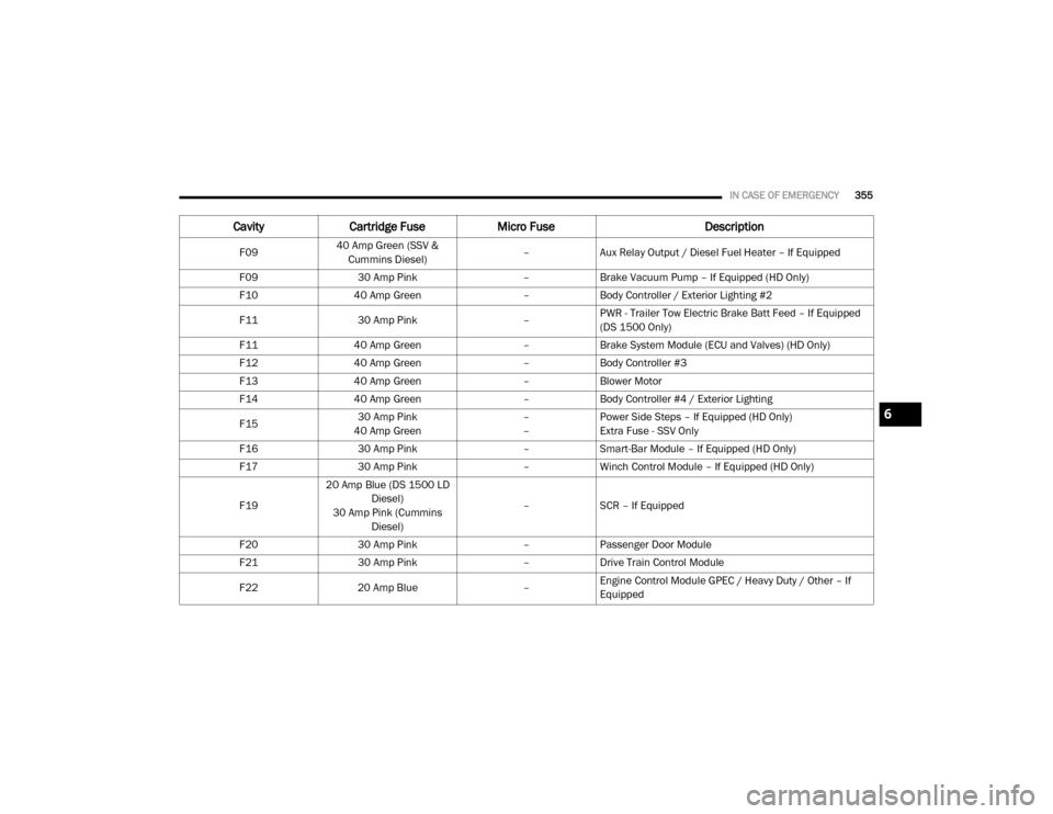
IN CASE OF EMERGENCY355
F0940 Amp Green (SSV &
Cummins Diesel) –
Aux Relay Output / Diesel Fuel Heater – If Equipped
F09 30 Amp Pink –Brake Vacuum Pump – If Equipped (HD Only)
F10 40 Amp Green –Body Controller / Exterior Lighting #2
F11 30 Amp Pink –PWR - Trailer Tow Electric Brake Batt Feed – If Equipped
(DS 1500 Only)
F11 40 Amp Green –Brake System Module (ECU and Valves) (HD Only)
F12 40 Amp Green –Body Controller #3
F13 40 Amp Green –Blower Motor
F14 40 Amp Green –Body Controller #4 / Exterior Lighting
F15 30 Amp Pink
40 Amp Green –
–Power Side Steps – If Equipped (HD Only)
Extra Fuse - SSV Only
F16 30 Amp Pink –Smart-Bar Module – If Equipped (HD Only)
F17 30 Amp Pink –Winch Control Module – If Equipped (HD Only)
F19 20 Amp Blue (DS 1500 LD
Diesel)
30 Amp Pink (Cummins Diesel) –
SCR – If Equipped
F20 30 Amp Pink –Passenger Door Module
F21 30 Amp Pink –Drive Train Control Module
F22 20 Amp Blue –Engine Control Module GPEC / Heavy Duty / Other – If
Equipped
Cavity
Cartridge Fuse Micro Fuse Description
6
20_DJD2_OM_EN_USC_t.book Page 355
Page 358 of 553
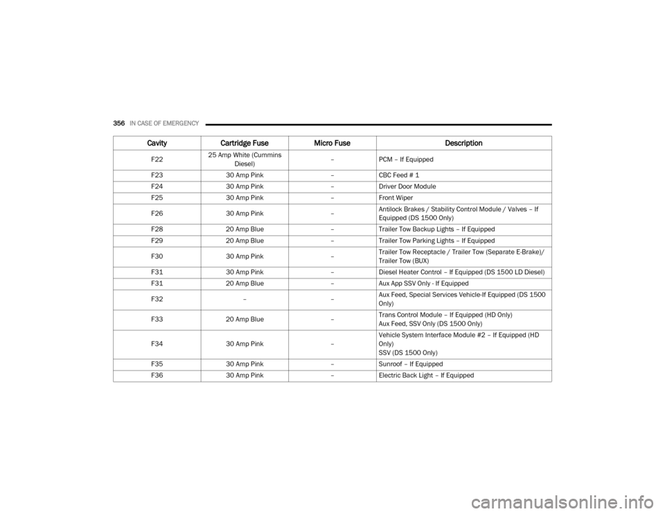
356IN CASE OF EMERGENCY
F2225 Amp White (Cummins
Diesel) –
PCM – If Equipped
F23 30 Amp Pink –CBC Feed # 1
F24 30 Amp Pink –Driver Door Module
F25 30 Amp Pink –Front Wiper
F26 30 Amp Pink –Antilock Brakes / Stability Control Module / Valves – If
Equipped (DS 1500 Only)
F28 20 Amp Blue –Trailer Tow Backup Lights – If Equipped
F29 20 Amp Blue –Trailer Tow Parking Lights – If Equipped
F30 30 Amp Pink –Trailer Tow Receptacle / Trailer Tow (Separate E-Brake)/
Trailer Tow (BUX)
F31 30 Amp Pink –Diesel Heater Control – If Equipped (DS 1500 LD Diesel)
F31 20 Amp Blue –Aux App SSV Only - If Equipped
F32 ––Aux Feed, Special Services Vehicle-If Equipped (DS 1500
Only)
F33 20 Amp Blue –Trans Control Module – If Equipped (HD Only)
Aux Feed, SSV Only (DS 1500 Only)
F34 30 Amp Pink –Vehicle System Interface Module #2 – If Equipped (HD
Only)
SSV (DS 1500 Only)
F35 30 Amp Pink –Sunroof – If Equipped
F36 30 Amp Pink –Electric Back Light – If Equipped
Cavity Cartridge Fuse Micro Fuse Description
20_DJD2_OM_EN_USC_t.book Page 356
Page 359 of 553
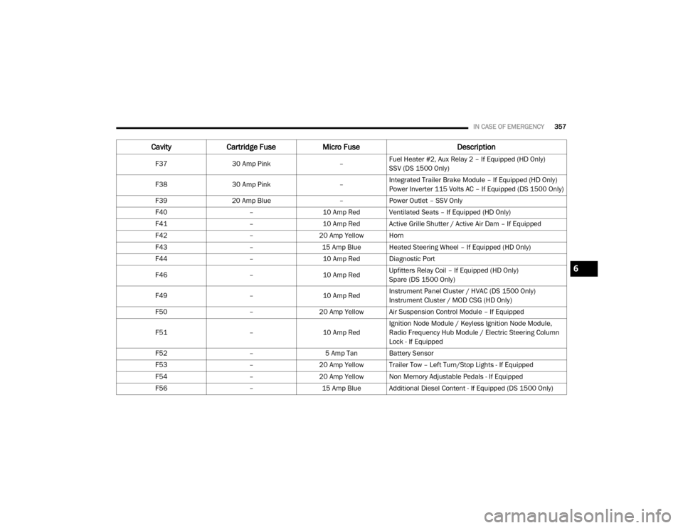
IN CASE OF EMERGENCY357
F3730 Amp Pink –Fuel Heater #2, Aux Relay 2 – If Equipped (HD Only)
SSV (DS 1500 Only)
F38 30 Amp Pink –Integrated Trailer Brake Module – If Equipped (HD Only)
Power Inverter 115 Volts AC – If Equipped (DS 1500 Only)
F39 20 Amp Blue –Power Outlet – SSV Only
F40 –10 Amp Red Ventilated Seats – If Equipped (HD Only)
F41 –10 Amp Red Active Grille Shutter / Active Air Dam – If Equipped
F42 –20 Amp Yellow Horn
F43 –15 Amp Blue Heated Steering Wheel – If Equipped (HD Only)
F44 –10 Amp Red Diagnostic Port
F46 –10 Amp RedUpfitters Relay Coil – If Equipped (HD Only)
Spare (DS 1500 Only)
F49 –10 Amp RedInstrument Panel Cluster / HVAC (DS 1500 Only)
Instrument Cluster / MOD CSG (HD Only)
F50 –20 Amp Yellow Air Suspension Control Module – If Equipped
F51 –10 Amp RedIgnition Node Module / Keyless Ignition Node Module,
Radio Frequency Hub Module / Electric Steering Column
Lock - If Equipped
F52 –5 Amp Tan Battery Sensor
F53 –20 Amp Yellow Trailer Tow – Left Turn/Stop Lights - If Equipped
F54 –20 Amp Yellow Non Memory Adjustable Pedals - If Equipped
F56 –15 Amp Blue Additional Diesel Content - If Equipped (DS 1500 Only)
CavityCartridge Fuse Micro Fuse Description
6
20_DJD2_OM_EN_USC_t.book Page 357
Page 360 of 553
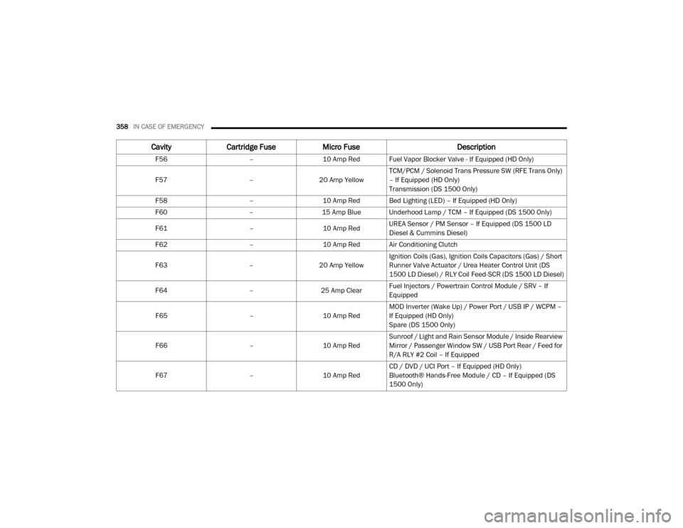
358IN CASE OF EMERGENCY
F56 –10 Amp Red Fuel Vapor Blocker Valve - If Equipped (HD Only)
F57 –20 Amp Yellow TCM/PCM / Solenoid Trans Pressure SW (RFE Trans Only)
– If Equipped (HD Only)
Transmission (DS 1500 Only)
F58 –10 Amp Red Bed Lighting (LED) – If Equipped (HD Only)
F60 –15 Amp Blue Underhood Lamp / TCM – If Equipped (DS 1500 Only)
F61 –10 Amp RedUREA Sensor / PM Sensor – If Equipped (DS 1500 LD
Diesel & Cummins Diesel)
F62 –10 Amp Red Air Conditioning Clutch
F63 –20 Amp Yellow Ignition Coils (Gas), Ignition Coils Capacitors (Gas) / Short
Runner Valve Actuator / Urea Heater Control Unit (DS
1500 LD Diesel) / RLY Coil Feed-SCR (DS 1500 LD Diesel)
F64 –25 Amp ClearFuel Injectors / Powertrain Control Module / SRV – If
Equipped
F65 –10 Amp RedMOD Inverter (Wake Up) / Power Port / USB IP / WCPM –
If Equipped (HD Only)
Spare (DS 1500 Only)
F66 –10 Amp RedSunroof / Light and Rain Sensor Module / Inside Rearview
Mirror / Passenger Window SW / USB Port Rear / Feed for
R/A RLY #2 Coil – If Equipped
F67 –10 Amp RedCD / DVD / UCI Port – If Equipped (HD Only)
Bluetooth® Hands-Free Module / CD – If Equipped (DS
1500 Only)
Cavity
Cartridge Fuse Micro Fuse Description
20_DJD2_OM_EN_USC_t.book Page 358
Page 361 of 553
IN CASE OF EMERGENCY359
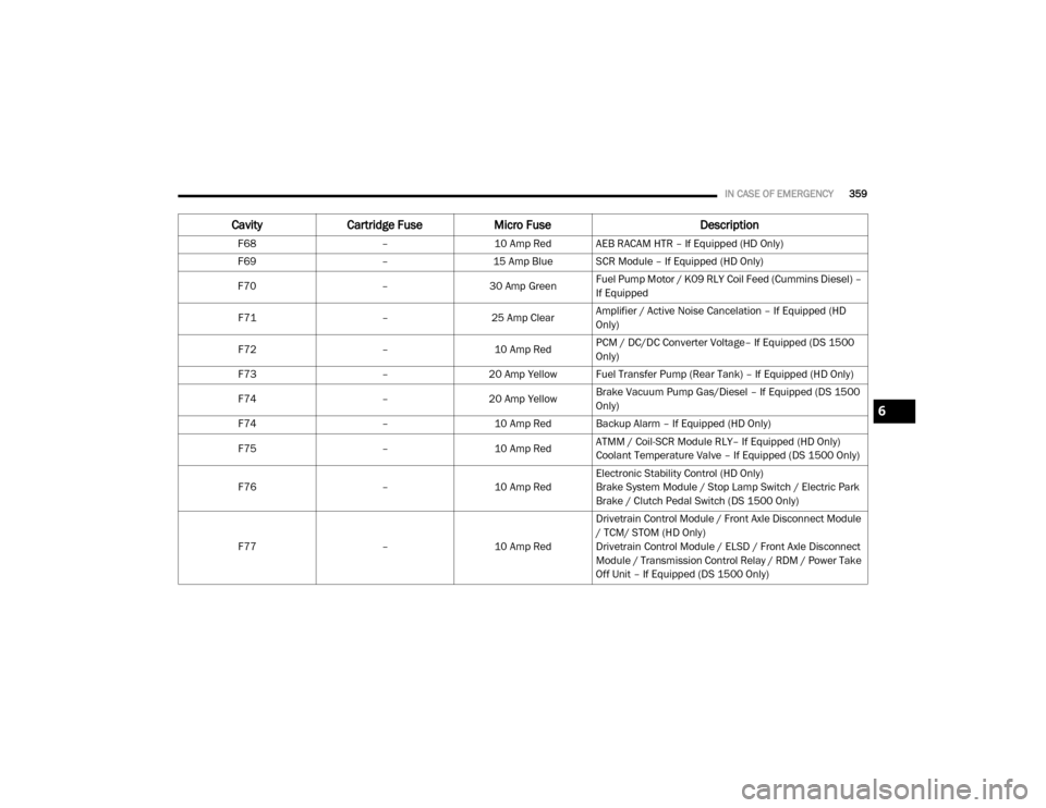
F68 –10 Amp Red AEB RACAM HTR – If Equipped (HD Only)
F69 –15 Amp Blue SCR Module – If Equipped (HD Only)
F70 –30 Amp GreenFuel Pump Motor / K09 RLY Coil Feed (Cummins Diesel) –
If Equipped
F71 –25 Amp ClearAmplifier / Active Noise Cancelation – If Equipped (HD
Only)
F72 –10 Amp RedPCM / DC/DC Converter Voltage– If Equipped (DS 1500
Only)
F73 –20 Amp Yellow Fuel Transfer Pump (Rear Tank) – If Equipped (HD Only)
F74 –20 Amp Yellow Brake Vacuum Pump Gas/Diesel – If Equipped (DS 1500
Only)
F74 –10 Amp Red Backup Alarm – If Equipped (HD Only)
F75 –10 Amp RedATMM / Coil-SCR Module RLY– If Equipped (HD Only)
Coolant Temperature Valve – If Equipped (DS 1500 Only)
F76 –10 Amp RedElectronic Stability Control (HD Only)
Brake System Module / Stop Lamp Switch / Electric Park
Brake / Clutch Pedal Switch (DS 1500 Only)
F77 –10 Amp RedDrivetrain Control Module / Front Axle Disconnect Module
/ TCM/ STOM (HD Only)
Drivetrain Control Module / ELSD / Front Axle Disconnect
Module / Transmission Control Relay / RDM / Power Take
Off Unit – If Equipped (DS 1500 Only)
Cavity
Cartridge Fuse Micro Fuse Description
6
20_DJD2_OM_EN_USC_t.book Page 359