warning Ram 2500 2020 Owner's Manual
[x] Cancel search | Manufacturer: RAM, Model Year: 2020, Model line: 2500, Model: Ram 2500 2020Pages: 553, PDF Size: 21.99 MB
Page 303 of 553
STARTING AND OPERATING301
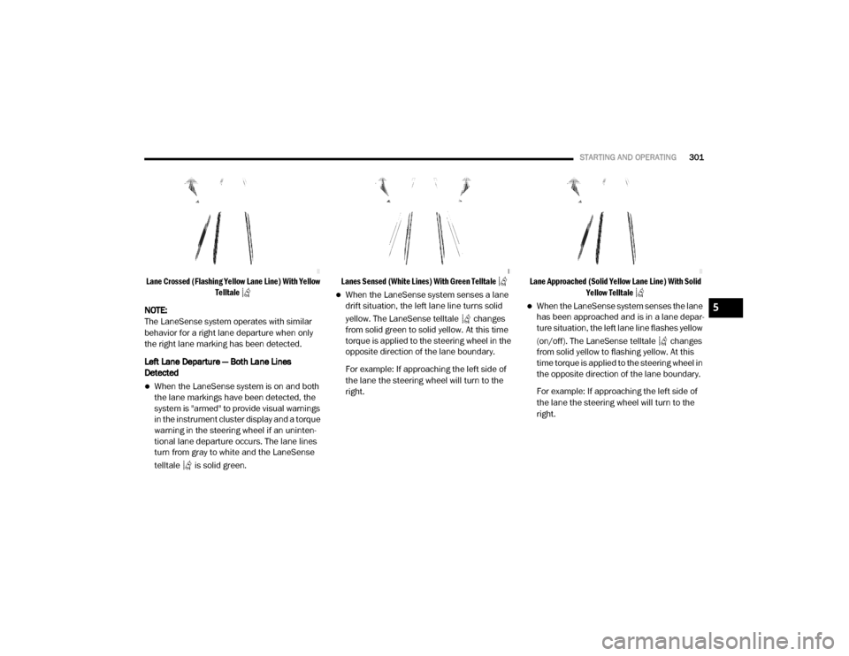
Lane Crossed (Flashing Yellow Lane Line) With Yellow
Telltale
NOTE:
The LaneSense system operates with similar
behavior for a right lane departure when only
the right lane marking has been detected.
Left Lane Departure — Both Lane Lines
Detected
When the LaneSense system is on and both
the lane markings have been detected, the
system is "armed" to provide visual warnings
in the instrument cluster display and a torque
warning in the steering wheel if an uninten -
tional lane departure occurs. The lane lines
turn from gray to white and the LaneSense
telltale is solid green.
Lanes Sensed (White Lines) With Green Telltale
When the LaneSense system senses a lane
drift situation, the left lane line turns solid
yellow. The LaneSense telltale changes
from solid green to solid yellow. At this time
torque is applied to the steering wheel in the
opposite direction of the lane boundary.
For example: If approaching the left side of
the lane the steering wheel will turn to the
right.
Lane Approached (Solid Yellow Lane Line) With Solid
Yellow Telltale
When the LaneSense system senses the lane
has been approached and is in a lane depar -
ture situation, the left lane line flashes yellow
(on/off). The LaneSense telltale changes
from solid yellow to flashing yellow. At this
time torque is applied to the steering wheel in
the opposite direction of the lane boundary.
For example: If approaching the left side of
the lane the steering wheel will turn to the
right.5
20_DJD2_OM_EN_USC_t.book Page 301
Page 304 of 553
302STARTING AND OPERATING
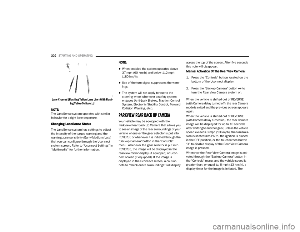
Lane Crossed (Flashing Yellow Lane Line) With Flash -
ing Yellow Telltale
NOTE:
The LaneSense system operates with similar
behavior for a right lane departure.
Changing LaneSense Status
The LaneSense system has settings to adjust
the intensity of the torque warning and the
warning zone sensitivity (Early/Medium/Late)
that you can configure through the Uconnect
system screen. Refer to “Uconnect Settings” in
“Multimedia” for further information. NOTE:
When enabled the system operates above
37 mph (60 km/h) and below 112 mph
(180 km/h).
Use of the turn signal suppresses the warn
-
ings.
The system will not apply torque to the
steering wheel whenever a safety system
engages (Anti-Lock Brakes, Traction Control
System, Electronic Stability Control, Forward
Collision Warning, etc.).
PARKVIEW REAR BACK UP CAMERA
Your vehicle may be equipped with the
ParkView Rear Back Up Camera that allows you
to see an image of the rear surroundings of your
vehicle whenever the gear selector is put into
REVERSE or whenever it is initiated through the
"Backup Camera" button in the "Controls"
menu. Whenever the gear selector is put into
REVERSE, the image will be displayed in the
rearview mirror display (if equipped) or Ucon -
nect screen (if equipped). If the image is
displayed in the Uconnect screen, a caution
note to “check entire surroundings” will display across the top of the screen. After five seconds
this note will disappear.
Manual Activation Of The Rear View Camera:
1. Press the "Controls" button located on the
bottom of the Uconnect display.
2. Press the "Backup Camera" button to turn the Rear View Camera system on.
When the vehicle is shifted out of REVERSE
(with Camera delay turned off), the rear Camera
mode is exited and the previous screen appears
again.
When the vehicle is shifted out of REVERSE
(with Camera delay turned on), the rear Camera
image will be displayed for up to 10 seconds
after shifting to another gear, unless the vehicle
speed exceeds 8 mph (13 km/h), the transmis- sion is shifted into PARK, the ignition is placed
in the OFF position, or the touchscreen button
“X” to disable display of the Rear View Camera
image is pressed.
Whenever the Rear View Camera image is acti -
vated through the "Backup Camera" button in
the "Controls" menu, and the vehicle speed is
greater than, or equal to, 8 mph (13 km/h), a display timer for the image is initiated. The
20_DJD2_OM_EN_USC_t.book Page 302
Page 305 of 553
STARTING AND OPERATING303
image will continue to be displayed until the
display timer exceeds 10 seconds.
NOTE:
If the vehicle speed remains below 8 mph
(13 km/h), the Rear View Camera image will
be displayed continuously until deactivated
via the touchscreen button "X", the transmis -
sion is shifted into PARK, or the ignition is
placed in the OFF position.
The touchscreen button "X" to disable display
of the camera image is made available ONLY
when the vehicle is not in REVERSE.
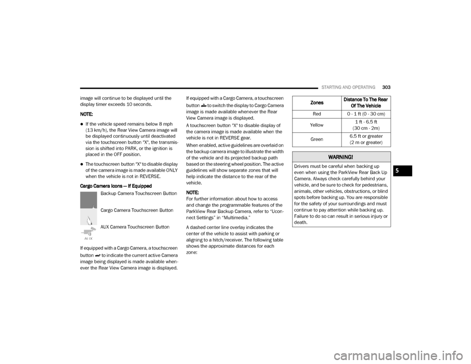
Cargo Camera Icons — If Equipped Backup Camera Touchscreen Button
Cargo Camera Touchscreen Button
AUX Camera Touchscreen Button
If equipped with a Cargo Camera, a touchscreen
button to indicate the current active Camera
image being displayed is made available when -
ever the Rear View Camera image is displayed. If equipped with a Cargo Camera, a touchscreen
button to switch the display to Cargo Camera
image is made available whenever the Rear
View Camera image is displayed.
A touchscreen button "X" to disable display of
the camera image is made available when the
vehicle is not in REVERSE gear.
When enabled, active guidelines are overlaid on
the backup camera image to illustrate the width
of the vehicle and its projected backup path
based on the steering wheel position. The active
guidelines will show separate zones that will
help indicate the distance to the rear of the
vehicle.
NOTE:
For further information about how to access
and change the programmable features of the
ParkView Rear Backup Camera, refer to “Ucon
-
nect Settings” in “Multimedia.”
A dashed center line overlay indicates the
center of the vehicle to assist with parking or
aligning to a hitch/receiver. The following table
shows the approximate distances for each
zone:
Zones Distance To The Rear
Of The Vehicle
Red 0 - 1 ft (0 - 30 cm)
Yellow 1 ft - 6.5 ft
(30 cm - 2m)
Green 6.5 ft or greater
(2 m or greater)
WARNING!
Drivers must be careful when backing up
even when using the ParkView Rear Back Up
Camera. Always check carefully behind your
vehicle, and be sure to check for pedestrians,
animals, other vehicles, obstructions, or blind
spots before backing up. You are responsible
for the safety of your surroundings and must
continue to pay attention while backing up.
Failure to do so can result in serious injury or
death.5
20_DJD2_OM_EN_USC_t.book Page 303
Page 312 of 553
310STARTING AND OPERATING
NOTE:
If the vehicle is in 4LO, the Forward Facing
Camera image will be displayed until the “X”
button is pressed or the ignition is placed in the
OFF position. If the vehicle goes out of 4LO, then
the regular deactivation conditions listed above
are applied.
Trailer Reverse Guidance — If Equipped
The Trailer Reverse Guidance feature assists
the driver in backing up a trailer by providing
adjustable camera views of the trailer and
surrounding area. The cameras are mounted on
the side mirrors and the images will be
displayed side-by-side on the touchscreen. Left
and right camera images are swapped and
mirrored on the touchscreen to show the equiv -
alent area behind the vehicle as though the
driver is using the side mirrors.
Activation
The Trailer Reverse Guidance feature can be
activated by pressing the Trailer Reverse Guid -
ance button on the Backup/Cargo Camera
Display. Deactivation
When the vehicle is shifted out of REVERSE
(with camera delay turned on), the camera
image will continue to be displayed for up to 10
seconds after shifting out of REVERSE unless
the vehicle speed exceeds 8 mph (13 km/h),
the vehicle is shifted into PARK or the ignition is
placed in the OFF position. There is a touch
-
screen button “X” to disable the display of the
camera image.
If Trailer Reverse Guidance is selected through
manually activated Surround View, Backup
Camera, or Cargo Camera, the below deactiva -
tion conditions are applied:
The “X” button on the display is pressed
The vehicle is shifted into PARK
The ignition is placed in the OFF position
The vehicle speed is over 8 mph (13 km/h)
for 10 seconds
WARNING!
Drivers must be careful when backing up
even when using the Surround View Camera.
Always check carefully behind your vehicle,
and be sure to check for pedestrians,
animals, other vehicles, obstructions, or blind
spots before backing up. You are responsible
for the safety of your surroundings and must
continue to pay attention while backing up.
Failure to do so can result in serious injury or
death.
CAUTION!
To avoid vehicle damage, Surround View
should only be used as a parking aid. The
Surround View camera is unable to view
every obstacle or object in your drive path.
To avoid vehicle damage, the vehicle must
be driven slowly when using Surround View
to be able to stop in time when an obstacle
is seen. It is recommended that the driver
look frequently over his/her shoulder when
using Surround View.
20_DJD2_OM_EN_USC_t.book Page 310
Page 314 of 553
312STARTING AND OPERATING
(Continued)
ENGINE RUNAWAY — DIESEL ENGINE
Diesel engine runaway is a rare condition
affecting diesel engines, where the engine
consumes its own lubrication oil and runs at
higher and higher RPM until it overspeeds to a
point where it destroys itself due to either
mechanical failure or engine seizure through
lack of lubrication.
REFUELING THE VEHICLE — GAS ENGINE
The fuel filler cap (gas cap) is located behind the
fuel filler door, on the left side of the vehicle.
Open the fuel door and remove the fuel filler cap
by turning it counter-clockwise.
Fuel Filler Cap
NOTE:
When removing the fuel filler cap, lay the cap
tether in the hook, located on the fuel filler door.
WARNING!
In case of engine runaway due to flammable
fumes from fuel spills or turbocharger oil
leaks being sucked into the engine, do the
following to help avoid personal injury and/or
vehicle damage:
1. Turn the ignition switch to the OFF position.
2. Using a CO2 or dry chemical type fire
extinguisher, direct the spray from the fire
extinguisher into the grille on the driver side
so that the spray enters the engine air intake.
The inlet for the engine air intake is located
behind the drivers side headlamp and
receives air through the grille.
WARNING!
Never have any smoking materials lit in or
near the vehicle when the gas cap is
removed or the tank is being filled.
Never add fuel to the vehicle when the
engine is running.
A fire may result if gasoline is pumped into
a portable container that is inside of a
vehicle. You could be burned. Always place
gas containers on the ground while filling.
CAUTION!
Damage to the fuel system or emissions
control system could result from using an
improper fuel tank filler tube cap.
A poorly fitting fuel filler cap could let impu -
rities into the fuel system.
A poorly fitting fuel filler cap may cause the
“Malfunction Indicator Light (MIL)” to turn
on.
To avoid fuel spillage and overfilling, do not
“top off” the fuel tank after filling. When the
fuel nozzle “clicks” or shuts off, the fuel
tank is full.
WARNING! (Continued)
20_DJD2_OM_EN_USC_t.book Page 312
Page 315 of 553
STARTING AND OPERATING313
NOTE:
When the fuel nozzle “clicks” or shuts off, the
fuel tank is full.
Tighten the gas cap until you hear a “clicking”
sound. This is an indication that the gas cap
is tightened properly. The MIL in the instru -
ment cluster may turn on if the gas cap is not
secured properly. Make sure that the gas cap
is tightened each time the vehicle is refueled.
Loose Fuel Filler Cap Message
If the vehicle diagnostic system deter -
mines that the fuel filler cap is loose,
improperly installed, or damaged, a
loose gASCAP indicator will display in
the instrument cluster telltale display area.
Refer to “Instrument Cluster Display” in
“Getting To Know Your Instrument Panel” for
further information. Tighten the fuel filler cap
properly and push the RIGHT button to turn off
the message. If the problem continues, the
message will appear the next time the vehicle is
started.
REFUELING THE VEHICLE — DIESEL ENGINE
1. Open the fuel filler door.
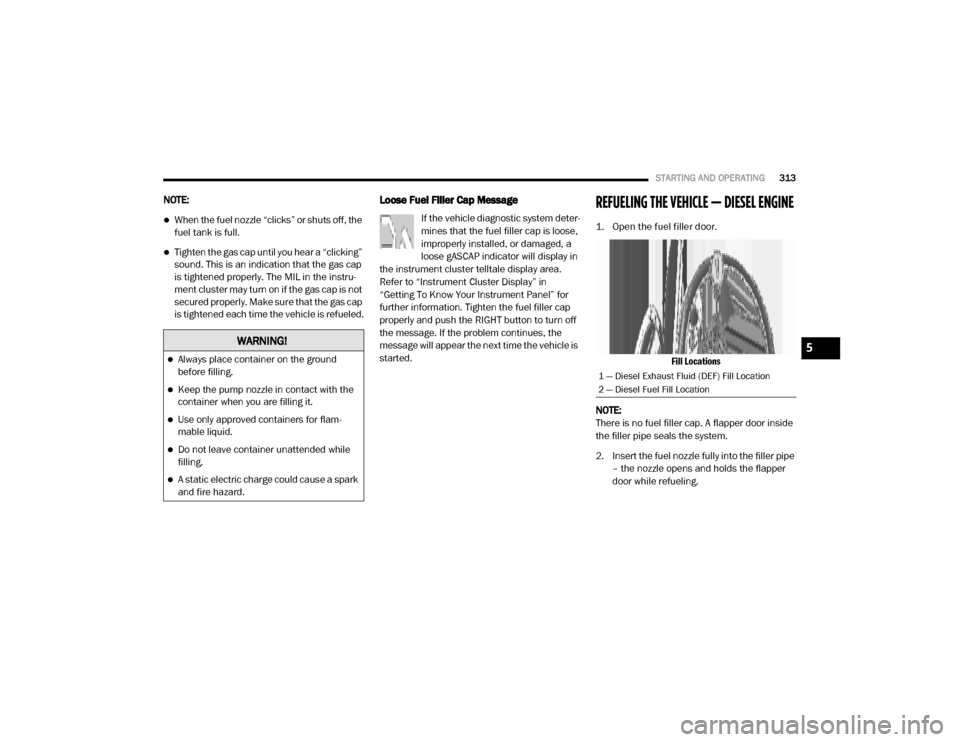
Fill Locations
NOTE:
There is no fuel filler cap. A flapper door inside
the filler pipe seals the system.
2. Insert the fuel nozzle fully into the filler pipe – the nozzle opens and holds the flapper
door while refueling.
WARNING!
Always place container on the ground
before filling.
Keep the pump nozzle in contact with the
container when you are filling it.
Use only approved containers for flam -
mable liquid.
Do not leave container unattended while
filling.
A static electric charge could cause a spark
and fire hazard.
1 — Diesel Exhaust Fluid (DEF) Fill Location
2 — Diesel Fuel Fill Location
5
20_DJD2_OM_EN_USC_t.book Page 313
Page 316 of 553

314STARTING AND OPERATING
(Continued)
3. Fill the vehicle with fuel – when the fuel nozzle “clicks” or shuts off the fuel tank is
full.
4. Remove the fuel nozzle and close the fuel door.
Emergency Fuel Can Refueling
NOTE:
In the event that you run the vehicle out of fuel,
once refueled, place the ignition in the ON posi -
tion for 30 seconds, then turn the ignition OFF
and wait 30 seconds. Repeat this procedure
three times, prior to cranking the engine.
Most fuel cans will not open the flapper door.
A funnel is provided to open the flapper door to
allow emergency refueling with a fuel can.
1. Retrieve fuel funnel from the jack kit located under the front passenger seat.
2. Insert funnel into same filler pipe opening as the fuel nozzle.
Fill Locations And Funnel Usage
NOTE:
Ensure funnel is inserted fully to hold flapper
door open.
3. Pour fuel into funnel opening.
4. Remove funnel from filler pipe, clean off prior to putting back in the jack kit.
Diesel Exhaust Fluid
Your vehicle is equipped with a Selective Cata-
lytic Reduction (SCR) system to meet the very
stringent diesel emissions standards required
by the Environmental Protection Agency.
The purpose of the SCR system is to reduce
levels of NOx (oxides of nitrogen emitted from
engines) that are harmful to our health and the
environment to a near-zero level. A small quan -
tity of Diesel Exhaust Fluid (DEF) is injected into
the exhaust upstream of a catalyst where, when
1 — Diesel Exhaust Fluid (DEF) Fill Location
2 — Emergency Diesel Fuel Fill Funnel
3 — Diesel Fuel Fill Location
WARNING!
Never have any smoking materials lit in or
near the vehicle when the fuel door is open
or the tank is being filled.
Never add fuel when the engine is running.
This is in violation of most state and federal
fire regulations and may cause the
“Malfunction Indicator Light” to turn on.
A fire may result if fuel is pumped into a
portable container that is inside of a
vehicle. You could be burned. Always place
fuel containers on the ground while filling.
CAUTION!
To avoid fuel spillage and overfilling, do not
“top off” the fuel tank after filling.
WARNING! (Continued)
20_DJD2_OM_EN_USC_t.book Page 314
Page 317 of 553

STARTING AND OPERATING315
vaporized, it converts smog-forming nitrogen
oxides (NOx) into harmless nitrogen (N2) and
water vapor (H2O), two natural components of
the air we breathe. You can operate with the
comfort that your vehicle is contributing to a
cleaner, healthier world environment for this
and generations to come.
System Overview
This vehicle is equipped with a Diesel Exhaust
Fluid (DEF) injection system and a Selective
Catalytic Reduction (SCR) catalyst to meet the
emission requirements.
The DEF injection system consists of the
following components:
DEF tank
DEF pump
DEF injector
Electronically-heated DEF lines
DEF control module
NOx sensors
Temperature sensors
SCR catalyst
UQS Sensor Refer to “Instrument Cluster Display” in
“Getting To Know Your Instrument Panel” for
system messages and warnings.
NOTE:
Your vehicle is equipped with a DEF injection
system. You may occasionally hear an
audible clicking noise. This is normal opera
-
tion.
The DEF pump will run for a period of time
after engine shutdown to purge the DEF
system. This is normal operation.
Diesel Exhaust Fluid Storage
Diesel Exhaust Fluid (DEF) is considered a very
stable product with a long shelf life. If DEF is
kept in temperatures between 10°F and 90°F
(-12°C and 32°C), it will last a minimum of one
year.
DEF is subject to freezing at the lowest tempera-
tures. For example, DEF may freeze at tempera-
tures at or below 12°F (-11°C). The system has
been designed to operate in this environment. NOTE:
When working with DEF, it is important to know
that:
Any containers or parts that come into
contact with DEF must be DEF compatible
(plastic or stainless steel). Copper, brass,
aluminum, iron or non-stainless steel should
be avoided as they are subject to corrosion
by DEF.
If DEF is spilled, it should be wiped up
completely.
Adding Diesel Exhaust Fluid
The DEF gauge (located on the instrument
cluster) will display the level of DEF remaining in
the tank. Refer to “Instrument Cluster” and
“Instrument Cluster Descriptions” in “Getting To
Know Your Instrument Panel” for further infor
-
mation.
NOTE:
Driving conditions (altitude, vehicle speed,
load, etc.) will affect the amount of DEF that
is used in your vehicle.
Another factor is that outside temperature
can affect DEF consumption. In cold condi -
tions, 12°F (-11°C) and below, the DEF
5
20_DJD2_OM_EN_USC_t.book Page 315
Page 321 of 553
STARTING AND OPERATING319
The recommended way to measure GTW is to
put your fully loaded trailer on a vehicle scale.
The entire weight of the trailer must be
supported by the scale.
Gross Combination Weight Rating (GCWR)
The GCWR is the total allowable weight of your
vehicle and trailer when weighed in combina -
tion.
Gross Axle Weight Rating (GAWR)
The GAWR is the maximum capacity of the front
and rear axles. Distribute the load over the front
and rear axles evenly. Make sure that you do
not exceed either front or rear GAWR. Refer to
“Vehicle Loading/Vehicle Certification Label” in
“Starting And Operating” for further informa -
tion.
Tongue Weight (TW)
The tongue weight is the downward force
exerted on the hitch ball by the trailer. You must
consider this as part of the load on your vehicle.
Trailer Frontal Area
The frontal area is the maximum height multi -
plied by the maximum width of the front of a
trailer.
Trailer Sway Control
The trailer sway control can be a mechanical
telescoping link that can be installed between
the hitch receiver and the trailer tongue that
typically provides adjustable friction associated
with the telescoping motion to dampen any
unwanted trailer swaying motions while trav -
eling. If equipped, the electronic Trailer Sway Control
(TSC) recognizes a swaying trailer and automat
-
ically applies individual wheel brakes and/or
reduces engine power to attempt to eliminate
the trailer sway.
Weight-Carrying Hitch
A weight-carrying hitch supports the trailer
tongue weight, just as if it were luggage located
at a hitch ball or some other connecting point of
the vehicle. These kinds of hitches are the most
popular on the market today and they are
commonly used to tow small and medium sized
trailers.
Weight-Distributing Hitch
A weight-distributing system works by applying
leverage through spring (load) bars. They are
typically used for heavier loads to distribute
trailer tongue weight to the tow vehicle's front
axle and the trailer axle(s). When used in accor -
dance with the manufacturer's directions, it
provides for a more level ride, offering more
consistent steering and brake control, thereby
enhancing towing safety. The addition of a fric -
tion/hydraulic sway control also dampens sway
caused by traffic and crosswinds and contrib -
utes positively to tow vehicle and trailer
stability. Trailer Sway Control (TSC) and a weight
WARNING!
If the gross trailer weight is 5,000 lbs (2,267 kg)
or more, it is recommended to use a
weight-distributing hitch to ensure stable
handling of your vehicle. If you use a standard
weight-carrying hitch, you could lose control of
your vehicle and cause a collision.
WARNING!
It is important that you do not exceed the
maximum front or rear GAWR. A dangerous
driving condition can result if either rating is
exceeded. You could lose control of the
vehicle and have a collision.
5
20_DJD2_OM_EN_USC_t.book Page 319
Page 322 of 553
320STARTING AND OPERATING
distributing (load equalizing) hitch are recom -
mended for heavier Tongue Weights (TW) and
may be required depending on vehicle and
trailer configuration/loading to comply with
GAWR requirements.
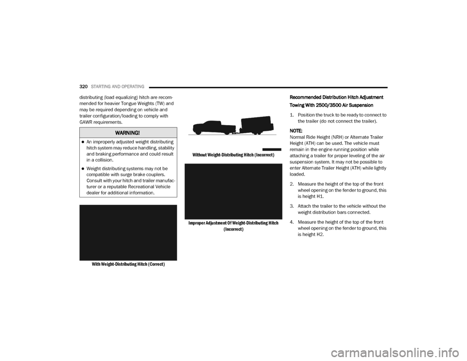
With Weight-Distributing Hitch (Correct) Without Weight-Distributing Hitch (Incorrect)
Improper Adjustment Of Weight-Distributing Hitch (Incorrect)
Recommended Distribution Hitch Adjustment
Towing With 2500/3500 Air Suspension
1. Position the truck to be ready to connect to
the trailer (do not connect the trailer).
NOTE:
Normal Ride Height (NRH) or Alternate Trailer
Height (ATH) can be used. The vehicle must
remain in the engine running position while
attaching a trailer for proper leveling of the air
suspension system. It may not be possible to
enter Alternate Trailer Height (ATH) while lightly
loaded.
2. Measure the height of the top of the front wheel opening on the fender to ground, this
is height H1.
3. Attach the trailer to the vehicle without the weight distribution bars connected.
4. Measure the height of the top of the front wheel opening on the fender to ground, this
is height H2.
WARNING!
An improperly adjusted weight distributing
hitch system may reduce handling, stability
and braking performance and could result
in a collision.
Weight distributing systems may not be
compatible with surge brake couplers.
Consult with your hitch and trailer manufac -
turer or a reputable Recreational Vehicle
dealer for additional information.
20_DJD2_OM_EN_USC_t.book Page 320