gear Ram 2500 2020 User Guide
[x] Cancel search | Manufacturer: RAM, Model Year: 2020, Model line: 2500, Model: Ram 2500 2020Pages: 553, PDF Size: 21.99 MB
Page 129 of 553

GETTING TO KNOW YOUR INSTRUMENT PANEL127
displayed. on pickup applications, and
approximately 7 gallons (26 Liters) are
required on chassis-cab applications.
Speed Limited to 5 MPH in XXX mi Refill DEF
— This message will continuously display if
the “DEF Low Refill Soon” message is
ignored, and the frequency of occurrence of
the chime will increase unless up to 2 gallons
(7.5 Liters) of DEF is added to the tank.
5 MPH Max Speed on Restart, Long Idle or
Refuel Refill DEF — This message will contin -
uously display when the counter reaches
zero, and will be accompanied by a periodic
chime.
The vehicle will only be capable of a
maximum speed of 5 MPH upon the first of
the following conditions to occur:
If the vehicle is shutoff and restarted.
If the vehicle is idled for an extended
period of time, approximately one hour or
greater.
If the system detects that the level of fuel in the tank has increased.
Add a minimum of 2 gallons (7.5 Liters) of DEF
to the tank in order to avoid vehicle operation
at a maximum speed of 5 MPH (8 km/H).
NOTE:
A minimum of 2 gallons (7.5 Liters) may be
required to restore normal vehicle operation.
Although the vehicle will start normally and can
be placed in gear after this message has been
initially displayed, extreme caution should be
utilized since the vehicle will only be capable of
maneuvering at a maximum speed of 5 MPH
(8 km/H).
Diesel Exhaust Fluid (DEF) Fault Warning
Messages
There are five different messages which are
displayed if the vehicle detects that the DEF
system has been filled with a fluid other than
DEF, has experienced component failures, or
when tampering has been detected. The vehicle
may be limited to a maximum speed of 5 MPH
(8 km/H) if the DEF system is not serviced
within less than 200 miles (322 km) of the fault
being detected.
When the DEF system needs to be serviced the
following warnings will display:
Service DEF System See Dealer — This
message will display when the fault is initially
detected, each time the vehicle is started,
and periodically during driving. The message
will be accompanied by a single chime. We
recommend you drive to your nearest autho -
rized dealer and have your vehicle serviced
as soon as possible.
5 MPH Max Speed in 150 mi Service DEF
System See Dealer — This message will
display if the DEF system has not been
serviced after the “Service DEF System – See
Dealer” message is displayed. This message
will continuously display until the mileage
counter reaches zero, and will be accompa -
nied by a periodic chime. The message will
continue to countdown until it reaches zero
unless the vehicle is serviced. We recom -
mend you drive to your nearest authorized
dealer and have your vehicle serviced imme -
diately.
NOTE:
Under some circumstances this mileage
counter may start with a value of less than
150 miles (241 km). For example, if recurring
faults are detected in a time interval of less
than 40 hours, the counter may restart at the
3
20_DJD2_OM_EN_USC_t.book Page 127
Page 130 of 553

128GETTING TO KNOW YOUR INSTRUMENT PANEL
value where it stopped when a previous fault
was temporarily remedied, or at a minimum of
50 miles (80 km).
5 MPH Max Speed on Restart, Long Idle or
Refuel Service DEF See Dealer — This
message will continuously display when the
mileage counter reaches zero, and will be
accompanied by a periodic chime.
The vehicle will only be capable of a
maximum speed of 5 MPH upon the first of
the following conditions to occur:
If the vehicle is shutoff and restarted.
If the vehicle is idled for an extended
period of time, approximately one hour or
greater.
If the system detects that the level of fuel in the tank has increased.
5 MPH Max Speed Service DEF System See
Dealer — This message will continuously
display, and will be accompanied by a peri -
odic chime. Although the vehicle can be
started and placed in gear, the vehicle will
only operate at a maximum speed of 5 MPH.
Your vehicle will require towing, see an
authorized dealer for service. NOTE:
When this message is displayed, the engine can
still be started. However, the vehicle will only
operate at a maximum speed of 5 MPH.
Incorrect DEF Detected See Dealer
— This
message will display when the fault is initially
detected, each time the vehicle is started,
and periodically during driving. The message
will be accompanied by a single chime. We
recommend you drive to your nearest autho -
rized dealer and have your vehicle serviced
as soon as possible.
RAM Active Air System
Your vehicle is equipped with an advanced Ram
Active Air system that provides enhanced
performance, especially when towing under
demanding hot or high altitude conditions. If the
instrument cluster display displays the
message “Active Airbox Service Required See
Dealer”, vehicle performance may be reduced
until service is performed by an authorized RAM
dealer.
Battery Saver On/Battery Saver Mode
Message — Electrical Load Reduction
Actions — If Equipped
This vehicle is equipped with an Intelligent
Battery Sensor (IBS) to perform additional moni -
toring of the electrical system and status of the
vehicle battery.
In cases when the IBS detects charging system
failure, or the vehicle battery conditions are
deteriorating, electrical load reduction actions
will take place to extend the driving time and
distance of the vehicle. This is done by reducing
power to or turning off non-essential electrical
loads.
Load reduction is only active when the engine is
running. It will display a message if there is a
risk of battery depletion to the point where the
vehicle may stall due to lack of electrical supply,
or will not restart after the current drive cycle.
When load reduction is activated, the message
“Battery Saver On Some Systems May Have
Reduced Power” will appear in the instrument
cluster.
These messages indicate the vehicle battery
has a low state of charge and continues to lose
electrical charge at a rate that the charging
system cannot sustain.
20_DJD2_OM_EN_USC_t.book Page 128
Page 141 of 553

GETTING TO KNOW YOUR INSTRUMENT PANEL139
4WD Lock Indicator Light
This light alerts the driver that the
vehicle is in the four-wheel drive LOCK
mode. The front and rear driveshafts
are mechanically locked together,
forcing the front and rear wheels to rotate at the
same speed.
Refer to “Four-Wheel Drive Operation” in
“Starting And Operating” for further information
on four-wheel drive operation and proper use.
4WD Low Indicator Light — If Equipped
This light alerts the driver that the
vehicle is in the four-wheel drive LOW
mode. The front and rear driveshafts
are mechanically locked together
forcing the front and rear wheels to rotate at the
same speed. Low range provides a greater gear
reduction ratio to provide increased torque at
the wheels.
Refer to “Four-Wheel Drive Operation — If
Equipped” in “Starting And Operating” for
further information on four-wheel drive opera -
tion and proper use.
4WD High Indicator Light — If Equipped
This light alerts the driver that the
vehicle is in the four-wheel drive HIGH
mode. The front and rear driveshafts
are mechanically locked together
forcing the front and rear wheels to rotate at the
same speed.
NEUTRAL Indicator Light — If Equipped
This light alerts the driver that the
4WD power transfer case is in the
NEUTRAL mode and the front and rear
driveshafts are disengaged from the
powertrain.
Low Diesel Exhaust Fluid (DEF) Indicator
Light — If Equipped
The Low Diesel Exhaust Fluid (DEF)
Indicator will illuminate if the vehicle
is low on Diesel Exhaust Fluid (DEF).
Refer to “Starting And Operating” for
further information.
Wait To Start Light — If Equipped
This indicator light will illuminate for
approximately two seconds when the
ignition is turned to the RUN position.
Its duration may be longer based on colder operating conditions. Vehicle will not
initiate start until telltale is no longer displayed.
Refer to “Starting The Engine” in “Starting And
Operating” for further information.
NOTE:
The “Wait To Start” telltale may not illuminate if
the intake manifold temperature is warm
enough.
Water In Fuel Indicator Light — If Equipped
The “Water In Fuel Indicator Light” will
illuminate when there is water
detected in the fuel filter. If this light
remains on, DO NOT start the vehicle
before you drain the water from the fuel filter to
prevent engine damage.
Refer to the “Draining Fuel/Water Separator
Filter” section in “Dealer Service” in “Servicing
And Maintenance” for further information.
3
20_DJD2_OM_EN_USC_t.book Page 139
Page 152 of 553

150SAFETY
Activating HDC
Once HDC is enabled it will activate automati -
cally if driven down a grade of sufficient magni -
tude. The set speed for HDC is selectable by the
driver, and can be adjusted by using the gear
shift +/-. The following summarizes the HDC set
speeds:
HDC Target Set Speeds
P = No set speed. HDC may be enabled but
will not activate.
R = 0.6 mph (1 km/h)
N = 1.2 mph (2 km/h)
D = 0.6 mph (1 km/h)
1st = 0.6 mph (1 km/h)
2nd = 1.2 mph (2 km/h)
3rd = 1.8 mph (3 km/h)
4th = 2.5 mph (4 km/h)
5th = 3.1 mph (5 km/h)
6th = 3.7 mph (6 km/h)
7th = 4.3 mph (7 km/h)
8th = 5.0 mph (8 km/h)
9th = 5.6 mph (9 km/h) – If Equipped
NOTE:
During HDC the +/- shifter input is used for HDC
target speed selection, but will not affect the
gear chosen by the transmission. When actively
controlling HDC the transmission will shift
appropriately for the driver-selected set speed
and corresponding driving conditions.
Driver Override
The driver may override HDC activation with
throttle or brake application at any time.
Deactivating HDC
HDC will be deactivated but remain available if
any of the following conditions occur:
Driver overrides HDC set speed with throttle
or brake application.
Vehicle speed exceeds 20 mph (32 km/h) but remains below 40 mph (64 km/h).
Vehicle is on a downhill grade of insufficient
magnitude, is on level ground, or is on an
uphill grade.
Vehicle is shifted to PARK. Disabling HDC
HDC will be deactivated and disabled if any of
the following conditions occur:
The driver pushes the HDC switch.
The driveline is shifted out of 4L Range.
The parking brake is applied.
The driver door opens.
The vehicle is driven greater than 20 mph
(32 km/h) for greater than 70 seconds.
The vehicle is driven greater than 40 mph
(64 km/h) (HDC exits immediately).
HDC detects excessive brake temperature.
Feedback To The Driver
The instrument cluster has an HDC icon and the
HDC switch has an LED icon, which offers feed -
back to the driver about the state HDC is in.
The cluster icon and switch lamp will illumi -
nate and remain on solid when HDC is
enabled or activated. This is the normal oper -
ating condition for HDC.
The cluster icon and switch lamp will flash for
several seconds then extinguish when the
driver pushes the HDC switch but enable
conditions are not met.
20_DJD2_OM_EN_USC_t.book Page 150
Page 153 of 553

SAFETY151
The cluster icon and switch lamp will flash for
several seconds then extinguish when HDC
disables due to excess speed.
The cluster icon and switch lamp will flash
when HDC deactivates due to overheated
brakes. The flashing will stop and HDC will
activate again once the brakes have cooled
sufficiently.
Hill Start Assist (HSA)
The Hill Start Assist (HSA) system is designed to
mitigate roll back from a complete stop while on
an incline. If the driver releases the brake while
stopped on an incline, HSA will continue to hold
the brake pressure for a short period. If the
driver does not apply the throttle before this
time expires, the system will release brake pres -
sure and the vehicle will roll down the hill as
normal. The following conditions must be met in order
for HSA to activate:
The feature must be enabled.
The vehicle must be stopped.
The park brake must be off.
The driver door must be closed.
The vehicle must be on a sufficient grade.
The gear selection must match vehicle uphill
direction (i.e., vehicle facing uphill is in
forward gear; vehicle backing uphill is in
REVERSE (R) gear).
HSA will work in REVERSE gear and all
forward gears. The system will not activate if
the transmission is in PARK or NEUTRAL (N).
For vehicles equipped with a manual trans
-
mission, if the clutch is pressed, HSA will
remain active.
WARNING!
HDC is only intended to assist the driver in
controlling vehicle speed when descending
hills. The driver must remain attentive to the
driving conditions and is responsible for
maintaining a safe vehicle speed.
WARNING!
There may be situations where the Hill Start
Assist (HSA) will not activate and slight rolling
may occur, such as on minor hills or with a
loaded vehicle, or while pulling a trailer. HSA
is not a substitute for active driving
involvement. It is always the driver’s
responsibility to be attentive to distance to
other vehicles, people, and objects, and most
importantly brake operation to ensure safe
operation of the vehicle under all road
conditions. Your complete attention is always
required while driving to maintain safe control
of your vehicle. Failure to follow these
warnings can result in a collision or serious
personal injury.
4
20_DJD2_OM_EN_USC_t.book Page 151
Page 155 of 553
SAFETY153
Traction Control System (TCS)
This system monitors the amount of wheel spin
of each of the driven wheels. If wheel spin is
detected, the Traction Control System (TCS)
may apply brake pressure to the spinning
wheel(s) and/or reduce engine power to provide
enhanced acceleration and stability. A feature
of the TCS, Brake Limited Differential (BLD),
functions similar to a limited slip differential
and controls the wheel spin across a driven
axle. If one wheel on a driven axle is spinning
faster than the other, the system will apply the
brake of the spinning wheel. This will allow more
engine power to be applied to the wheel that is
not spinning. BLD may remain enabled even if
TCS and Electronic Stability Control (ESC) are in
a reduced mode.
Trailer Sway Control (TSC)
Trailer Sway Control (TSC) uses sensors in the
vehicle to recognize an excessively swaying
trailer and will take the appropriate actions to
attempt to stop the sway. TSC will become
active automatically once an excessively
swaying trailer is recognized. NOTE:
TSC cannot stop all trailers from swaying.
Always use caution when towing a trailer and
follow the trailer tongue weight recommenda
-
tions. Refer to “Trailer Towing” in “Starting And
Operating” for further information.
When TSC is functioning, the “ESC Activation/
Malfunction Indicator Light” will flash, the
engine power may be reduced and you may feel
the brakes being applied to individual wheels to
attempt to stop the trailer from swaying. TSC is
disabled when the ESC system is in the “Partial
Off” or “Full Off” modes.
AUXILIARY DRIVING SYSTEMS
Blind Spot Monitoring (BSM) — If Equipped
The Blind Spot Monitoring (BSM) system uses
two radar-based sensors, located inside the tail -
lights, to detect highway licensable vehicles
(automobiles, trucks, motorcycles, etc.) that enter the blind spot zones from the rear/front/
side of the vehicle.
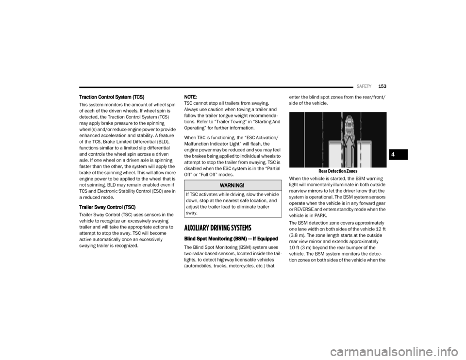
Rear Detection Zones
When the vehicle is started, the BSM warning
light will momentarily illuminate in both outside
rearview mirrors to let the driver know that the
system is operational. The BSM system sensors
operate when the vehicle is in any forward gear
or REVERSE and enters standby mode when the
vehicle is in PARK.
The BSM detection zone covers approximately
one lane width on both sides of the vehicle 12 ft
(3.8 m). The zone length starts at the outside
rear view mirror and extends approximately
10 ft (3 m) beyond the rear bumper of the
vehicle. The BSM system monitors the detec -
tion zones on both sides of the vehicle when the
WARNING!
If TSC activates while driving, slow the vehicle
down, stop at the nearest safe location, and
adjust the trailer load to eliminate trailer
sway.
4
20_DJD2_OM_EN_USC_t.book Page 153
Page 191 of 553

SAFETY189
(Continued)
Enhanced Accident Response System
In the event of an impact, if the communication
network remains intact, and the power remains
intact, depending on the nature of the event,
the Occupant Restraint Controller (ORC) will
determine whether to have the Enhanced Acci -
dent Response System perform the following
functions:
Cut off fuel to the engine (if equipped)
Cut off battery power to the electric motor (if
equipped)
Flash hazard lights as long as the battery has
power
Turn on the interior lights, which remain on
as long as the battery has power or for
15 minutes from the intervention of the
Enhanced Accident Response System
Unlock the power door locks
Your vehicle may also be designed to perform
any of these other functions in response to the
Enhanced Accident Response System:
Turn off the Fuel Filter Heater, Turn off the
HVAC Blower Motor, Close the HVAC Circula -
tion Door
Cut off battery power to the:
Engine
Electric Motor (if equipped)
Electric power steering
Brake booster
Electric park brake
Automatic transmission gear selector
Horn
Front wiper
Headlamp washer pump
NOTE:
After an accident, remember to cycle the ignition
to the STOP (OFF/LOCK) position and remove the
key from the ignition switch to avoid draining the
battery. Carefully check the vehicle for fuel leaks
in the engine compartment and on the ground
near the engine compartment and fuel tank
before resetting the system and starting the
engine. If there are no fuel leaks or damage to the
vehicle electrical devices (e.g. headlights) after an
accident, reset the system by following the proce -
dure described below. If you have any doubt,
contact an authorized dealer.
Enhanced Accident Response System Reset
Procedure
In order to reset the Enhanced Accident
Response System functions after an event, the
ignition switch must be changed from ignition
START or ON/RUN to ignition OFF. Carefully
check the vehicle for fuel leaks in the engine
compartment and on the ground near the
engine compartment and fuel tank before reset -
ting the system and starting the engine.
Maintaining Your Air Bag System
WARNING!
Modifications to any part of the air bag
system could cause it to fail when you need
it. You could be injured if the air bag system
is not there to protect you. Do not modify
the components or wiring, including adding
any kind of badges or stickers to the
steering wheel hub trim cover or the upper
passenger side of the instrument panel. Do
not modify the front bumper, vehicle body
structure, or add aftermarket side steps or
running boards.
4
20_DJD2_OM_EN_USC_t.book Page 189
Page 213 of 553

211
(Continued)
STARTING AND OPERATING
STARTING THE ENGINE — GAS ENGINE
Before starting your vehicle, adjust your seat,
adjust both inside and outside mirrors, and
fasten your seat belt.
The starter should not be operated for more
than 10-second intervals. Waiting a few
seconds between such intervals will protect the
starter from overheating.
Automatic Transmission
Start the engine with the transmission in PARK
position. Apply the brake before shifting into any
driving range.
NOTE:
This vehicle is equipped with a transmission
shift interlocking system. The brake pedal
must be pressed to shift out of PARK.
If equipped with an 8-speed transmission,
starting the vehicle in NEUTRAL is not
possible unless the Manual Park Release has
been activated. For the Manual Park Release
operation refer to Manual Park Release in “In
Case Of Emergency”.
Tip Start Feature
Do not press the accelerator. Cycle the ignition
switch briefly to the START position and release
it. The starter motor will continue to run and will
automatically disengage when the engine is
running.
Keyless Enter-N-Go — Ignition
Keyless Push Button Ignition
WARNING!
When leaving the vehicle, always make
sure the keyless ignition node is in the
"OFF" mode, remove the key fob from the
vehicle and lock the vehicle.
Never leave children alone in a vehicle, or
with access to an unlocked vehicle.
Allowing children to be in a vehicle unat -
tended is dangerous for a number of
reasons. A child or others could be seriously
or fatally injured. Children should be
warned not to touch the parking brake,
brake pedal or the gear selector.
Do not leave the key fob in or near the
vehicle, or in a location accessible to chil -
dren, and do not leave the ignition of a
vehicle equipped with Keyless Enter-N-Go
in the ACC or ON/RUN mode. A child could
operate power windows, other controls, or
move the vehicle.
Do not leave children or animals inside
parked vehicles in hot weather. Interior
heat build-up may cause serious injury or
death.
WARNING! (Continued)
5
20_DJD2_OM_EN_USC_t.book Page 211
Page 214 of 553

212STARTING AND OPERATING
This feature allows the driver to operate the igni -
tion switch with the push of a button, as long as
the Remote Start/Keyless Enter-N-Go key fob is
in the passenger compartment.
Normal Starting Using ENGINE START/STOP
Button
To Turn On The Engine Using The ENGINE
START/STOP Button
1. The transmission must be in PARK.
2. Press and hold the brake pedal while pushing the ENGINE START/STOP button
once.
3. The system takes over and attempts to start the vehicle. If the vehicle fails to start, the
starter will disengage automatically after 10
seconds.
4. If you wish to stop the cranking of the engine prior to the engine starting, push the
ENGINE START/STOP button again.
NOTE:
Normal starting of either a cold or a warm
engine is obtained without pumping or pressing
the accelerator pedal. To Turn Off The Engine Using ENGINE START/
STOP Button
1. Place the gear selector in PARK, then push
and release the ENGINE START/STOP
button.
2. The ignition will return to the OFF mode.
3. If the gear selector is not in PARK, the ENGINE START/STOP button must be held
for two seconds or three short pushes in a
row with the vehicle speed above 5 mph
(8 km/h) before the engine will shut off. The
ignition will remain in the ACC mode until
the gear selector is in PARK and the button
is pushed twice to the OFF mode.
4. If the gear selector is not in PARK and the ENGINE START/STOP button is pushed
once with the vehicle speed above 5 mph
(8 km/h), the instrument cluster will display
a “Vehicle Not In Park ” message and the
engine will remain running. Never leave a
vehicle out of the PARK position, or it could
roll.
NOTE:
If the gear selector is not in PARK, and the
ENGINE START/STOP button is pushed once with the vehicle speed below 5 mph (8 km/h),
the engine will shut off and the ignition will
remain in the ACC position. If vehicle speed
drops below 1.2 mph (1.9 km/h), the vehicle
may AutoPark. See AutoPark section for further
details.
ENGINE START/STOP Button Functions — With
Driver’s Foot OFF The Brake Pedal (In PARK Or
NEUTRAL Position)
The ENGINE START/STOP button operates
similar to an ignition switch. It has three modes:
OFF, ACC, and RUN. To change the ignition
modes without starting the vehicle and use the
accessories, follow these directions:
1. Start with the ignition in the OFF mode.
2. Push the ENGINE START/STOP button once to place the ignition to the ACC mode.
3. Push the ENGINE START/STOP button a second time to place the ignition to the RUN
mode.
4. Push the ENGINE START/STOP button a third time to return the ignition to the OFF
mode.
20_DJD2_OM_EN_USC_t.book Page 212
Page 215 of 553

STARTING AND OPERATING213
(Continued)
AutoPark — Rotary Shifter and 8-Speed
Transmission Only
AutoPark is a supplemental feature to assist in
placing the vehicle in PARK should the situa-
tions on the following pages occur. It is a back
up system and should not be relied upon as the
primary method by which the driver shifts the
vehicle into PARK.
The conditions under which AutoPark will
engage are outlined on the following pages. If the vehicle is not in PARK and the driver turns
off the engine, the vehicle may AutoPark.
AutoPark will engage when all of these condi
-
tions are met:
Vehicle is equipped with a rotary shifter and
an 8-speed transmission
Vehicle is not in PARK
Vehicle speed is 1.2 mph (1.9 km/h) or less
Ignition switched from RUN to ACC
NOTE:
For Keyless Enter-N-Go equipped vehicles, The
engine will turn off and the ignition switch will
change to ACC mode. After 30 minutes the igni -
tion switches to OFF automatically, unless the
driver turns the ignition switch OFF. If the vehicle is not in PARK and the driver exits
the vehicle with the engine running, the vehicle
may AutoPark.
AutoPark will engage when all of these condi
-
tions are met:
Vehicle is equipped with a rotary shifter and
an 8-speed transmission
Vehicle is not in PARK
Vehicle speed is 1.2 mph (1.9 km/h) or less
Driver’s seat belt is unbuckled
Driver’s door is ajar
Brake pedal is not depressed
The message “ AutoPark Engaged Shift to P then
Shift to Gear ” will display in the instrument
cluster.
NOTE:
In some cases the ParkSense graphic will be
displayed in the instrument cluster, causing the
“ AutoPark Engaged Shift to P then Shift to Gear ”
to not be seen. In these cases, the shifter must
be returned to “P” to select desired gear.
WARNING!
Driver inattention could lead to failure to
place the vehicle in PARK. ALWAYS DO A
VISUAL CHECK that your vehicle is in PARK
by verifying that a solid (not blinking) “P” is
indicated in the Instrument Cluster Display
and near the gear selector. If the “P” indi -
cator is blinking, your vehicle is not in
PARK. As an added precaution, always
apply the parking brake when exiting the
vehicle.
AutoPark is a supplemental feature. It is not
designed to replace the need to shift your
vehicle into PARK. It is a back up system
and should not be relied upon as the
primary method by which the driver shifts
the vehicle into PARK.
WARNING! (Continued)
5
20_DJD2_OM_EN_USC_t.book Page 213