wheel size Ram 2500 2020 User Guide
[x] Cancel search | Manufacturer: RAM, Model Year: 2020, Model line: 2500, Model: Ram 2500 2020Pages: 553, PDF Size: 21.99 MB
Page 279 of 553
STARTING AND OPERATING277
Adaptive Cruise Control (ACC) Operation
The speed control buttons (located on the right
side of the steering wheel) operate the ACC
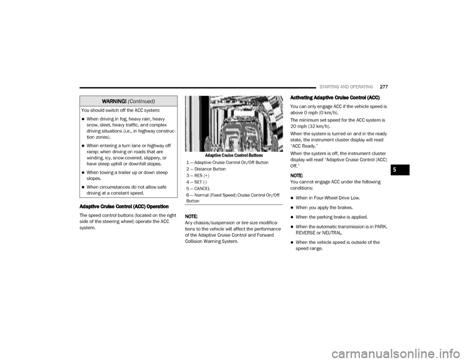
system.
Adaptive Cruise Control Buttons
NOTE:
Any chassis/suspension or tire size modifica -
tions to the vehicle will affect the performance
of the Adaptive Cruise Control and Forward
Collision Warning System.
Activating Adaptive Cruise Control (ACC)
You can only engage ACC if the vehicle speed is
above 0 mph (0 km/h).
The minimum set speed for the ACC system is
20 mph (32 km/h).
When the system is turned on and in the ready
state, the instrument cluster display will read
“ACC Ready.”
When the system is off, the instrument cluster
display will read “Adaptive Cruise Control (ACC)
Off.”
NOTE:
You cannot engage ACC under the following
conditions:
When in Four-Wheel Drive Low.
When you apply the brakes.
When the parking brake is applied.
When the automatic transmission is in PARK,
REVERSE or NEUTRAL.
When the vehicle speed is outside of the
speed range.
You should switch off the ACC system:
When driving in fog, heavy rain, heavy
snow, sleet, heavy traffic, and complex
driving situations (i.e., in highway construc
-
tion zones).
When entering a turn lane or highway off
ramp; when driving on roads that are
winding, icy, snow-covered, slippery, or
have steep uphill or downhill slopes.
When towing a trailer up or down steep
slopes.
When circumstances do not allow safe
driving at a constant speed.
WARNING! (Continued)
1 — Adaptive Cruise Control On/Off Button
2 — Distance Button
3 — RES (+)
4 — SET (-)
5 — CANCEL
6 — Normal (Fixed Speed) Cruise Control On/Off
Button
5
20_DJD2_OM_EN_USC_t.book Page 277
Page 301 of 553
STARTING AND OPERATING299
LANESENSE — IF EQUIPPED
LaneSense Operation
The LaneSense system is operational at speeds
above 37 mph (60 km/h) and below 112 mph
(180 km/h). It uses a forward looking camera to
detect lane markings and measure vehicle posi -
tion within the lane boundaries.
When both lane markings are detected and the
driver unintentionally drifts out of the lane while
no turn signal has been applied OR the driver
departs the lane on the opposite side of the
applied turn signal (if the left turn signal is applied and the vehicle departs to the right), the
LaneSense system provides a haptic warning in
the form of torque applied to the steering wheel
to prompt the driver to remain within the lane
boundaries. The LaneSense system will also
provide a visual warning through the instrument
cluster display to prompt the driver to remain
within the lane boundaries.
The driver may manually override the haptic
warning by applying torque into the steering
wheel at any time.
When only a single lane marking is detected
and the driver unintentionally drifts across that
lane marking (no turn signal applied), the Lane
-
Sense system provides a visual warning
through the instrument cluster display to
prompt the driver to remain within the lane.
When only a single lane marking is detected, a
haptic (torque) warning will not be provided.
NOTE:
When operating conditions have been met, the
LaneSense system will monitor if the driver’s
hands are on the steering wheel and provides
an audible and visual warning to the driver
when the driver’s hands are not detected on the
steering wheel. The system will cancel if the
driver does not return their hands to the wheel.
WARNING!
Drivers must be careful when backing up
even when using ParkSense. Always check
carefully behind your vehicle, look behind
you, and be sure to check for pedestrians,
animals, other vehicles, obstructions, and
blind spots before backing up. You are
responsible for safety and must continue to
pay attention to your surroundings. Failure
to do so can result in serious injury or
death.
Before using ParkSense, it is strongly
recommended that the ball mount and
hitch ball assembly is disconnected from
the vehicle when the vehicle is not used for
towing. Failure to do so can result in injury
or damage to vehicles or obstacles
because the hitch ball will be much closer
to the obstacle than the rear fascia when
the loudspeaker sounds the continuous
tone. Also, the sensors could detect the ball
mount and hitch ball assembly, depending
on its size and shape, giving a false indica -
tion that an obstacle is behind the vehicle.
CAUTION!
ParkSense is only a parking aid and it is
unable to recognize every obstacle,
including small obstacles. Parking curbs
might be temporarily detected or not
detected at all. Obstacles located above or
below the sensors will not be detected
when they are in close proximity.
The vehicle must be driven slowly when
using ParkSense in order to be able to stop
in time when an obstacle is detected. It is
recommended that the driver looks over
his/her shoulder when using ParkSense.
5
20_DJD2_OM_EN_USC_t.book Page 299
Page 319 of 553
STARTING AND OPERATING317
3. Stop filling the DEF tank immediately when
any of the following happen: DEF stops
flowing from the fill bottle into the DEF tank,
DEF splashes out the filler neck, or a DEF
pump nozzle automatically shuts off.
4. Reinstall cap onto DEF tank.
Filling The Def Tank In Cold Climates
Since DEF will begin to freeze at 12°F (-11°C),
your vehicle is equipped with an automatic DEF
heating system. This allows the DEF injection system to operate properly at temperatures
below 12°F (-11°C). If your vehicle is not in
operation for an extended period of time with
temperatures below 12°F (-11°C), the DEF in
the tank may freeze. If the tank is overfilled and
freezes, it could be damaged. Therefore, do not
overfill the DEF tank.
Extra care should be taken when filling with
portable containers to avoid overfilling. Note the
level of the DEF gauge in your instrument cluster.
You may safely add a maximum of 2 Gallons
(7.5 Liters) of DEF from portable containers
when your DEF gauge is reading ½ full.
VEHICLE LOADING
Gross Vehicle Weight Rating (GVWR)
The GVWR is the total permissible weight of your
vehicle including driver, passengers, vehicle,
options and cargo. The label also specifies
maximum capacities of front and rear axle
systems (GAWR). Total load must be limited so
GVWR and front and rear GAWR are not
exceeded.
Payload
The payload of a vehicle is defined as the allow
-
able load weight a truck can carry, including the
weight of the driver, all passengers, options and
cargo.
Gross Axle Weight Rating (GAWR)
The GAWR is the maximum permissible load on
the front and rear axles. The load must be
distributed in the cargo area so that the GAWR
of each axle is not exceeded.
Each axle GAWR is determined by the compo -
nents in the system with the lowest load
carrying capacity (axle, springs, tires or wheels).
Heavier axles or suspension components some -
times specified by purchasers for increased
durability does not necessarily increase the
vehicle's GVWR.
Tire Size
The tire size on the Vehicle Certification Label
represents the actual tire size on your vehicle.
Replacement tires must be equal to the load
capacity of this tire size.
Never add anything other than DEF to the
tank – especially any form of hydrocarbon
such as diesel fuel, fuel system additives,
gasoline, or any other petroleum-based
product. Even a very small amount of these,
less than 100 parts per million or less than
1 oz. per 78 Gallons (295 Liters) will
contaminate the entire DEF system and will
require replacement. If owners use a
container, funnel or nozzle when refilling
the tank, it should either be new or one that
is has only been used for adding DEF.
Mopar provides an attachable nozzle with
its DEF for this purpose.
CAUTION! (Continued)
5
20_DJD2_OM_EN_USC_t.book Page 317
Page 321 of 553
STARTING AND OPERATING319
The recommended way to measure GTW is to
put your fully loaded trailer on a vehicle scale.
The entire weight of the trailer must be
supported by the scale.
Gross Combination Weight Rating (GCWR)
The GCWR is the total allowable weight of your
vehicle and trailer when weighed in combina -
tion.
Gross Axle Weight Rating (GAWR)
The GAWR is the maximum capacity of the front
and rear axles. Distribute the load over the front
and rear axles evenly. Make sure that you do
not exceed either front or rear GAWR. Refer to
“Vehicle Loading/Vehicle Certification Label” in
“Starting And Operating” for further informa -
tion.
Tongue Weight (TW)
The tongue weight is the downward force
exerted on the hitch ball by the trailer. You must
consider this as part of the load on your vehicle.
Trailer Frontal Area
The frontal area is the maximum height multi -
plied by the maximum width of the front of a
trailer.
Trailer Sway Control
The trailer sway control can be a mechanical
telescoping link that can be installed between
the hitch receiver and the trailer tongue that
typically provides adjustable friction associated
with the telescoping motion to dampen any
unwanted trailer swaying motions while trav -
eling. If equipped, the electronic Trailer Sway Control
(TSC) recognizes a swaying trailer and automat
-
ically applies individual wheel brakes and/or
reduces engine power to attempt to eliminate
the trailer sway.
Weight-Carrying Hitch
A weight-carrying hitch supports the trailer
tongue weight, just as if it were luggage located
at a hitch ball or some other connecting point of
the vehicle. These kinds of hitches are the most
popular on the market today and they are
commonly used to tow small and medium sized
trailers.
Weight-Distributing Hitch
A weight-distributing system works by applying
leverage through spring (load) bars. They are
typically used for heavier loads to distribute
trailer tongue weight to the tow vehicle's front
axle and the trailer axle(s). When used in accor -
dance with the manufacturer's directions, it
provides for a more level ride, offering more
consistent steering and brake control, thereby
enhancing towing safety. The addition of a fric -
tion/hydraulic sway control also dampens sway
caused by traffic and crosswinds and contrib -
utes positively to tow vehicle and trailer
stability. Trailer Sway Control (TSC) and a weight
WARNING!
If the gross trailer weight is 5,000 lbs (2,267 kg)
or more, it is recommended to use a
weight-distributing hitch to ensure stable
handling of your vehicle. If you use a standard
weight-carrying hitch, you could lose control of
your vehicle and cause a collision.
WARNING!
It is important that you do not exceed the
maximum front or rear GAWR. A dangerous
driving condition can result if either rating is
exceeded. You could lose control of the
vehicle and have a collision.
5
20_DJD2_OM_EN_USC_t.book Page 319
Page 326 of 553
324STARTING AND OPERATING
(Continued)
Towing Requirements — Tires
Do not attempt to tow a trailer while using a
compact spare tire.
Do not drive more than 50 mph (80 km/h) when towing while using a full size spare tire.
Proper tire inflation pressures are essential
to the safe and satisfactory operation of your
vehicle. Refer to “Tires” in “Servicing And
Maintenance” for proper tire inflation proce -
dures.
Check the trailer tires for proper tire inflation
pressures before trailer usage.
Check for signs of tire wear or visible tire
damage before towing a trailer. Refer to
“Tires” in “Servicing And Maintenance” for
the proper inspection procedure.
When replacing tires, refer to “Tires” in
“Servicing And Maintenance” for the proper
tire replacement procedures. Replacing tires
with a higher load carrying capacity will not
increase the vehicle's GVWR and GAWR
limits.
Towing Requirements — Trailer Brakes
Do not interconnect the hydraulic brake
system or vacuum system of your vehicle
with that of the trailer. This could cause inad -
equate braking and possible personal injury.
An electronically actuated trailer brake
controller is required when towing a trailer
with electronically actuated brakes. When
towing a trailer equipped with a hydraulic
surge actuated brake system, an electronic
brake controller is not required.
Trailer brakes are recommended for trailers
over 1,000 lbs (453 kg) and required for
trailers in excess of 2,000 lbs (907 kg).
When hauling cargo or towing a trailer, do
not overload your vehicle or trailer. Over -
loading can cause a loss of control, poor
performance or damage to brakes, axle,
engine, transmission, steering, suspension,
chassis structure or tires.
Safety chains must always be used
between your vehicle and trailer. Always
connect the chains to the hook retainers of
the vehicle hitch. Cross the chains under
the trailer tongue and allow enough slack
for turning corners.
Vehicles with trailers should not be parked
on a grade. When parking, apply the
parking brake on the tow vehicle. Put the
tow vehicle transmission in PARK. For
four-wheel drive vehicles, make sure the
transfer case is not in NEUTRAL. Always,
block or "chock" the trailer wheels.
GCWR must not be exceeded.
WARNING! (Continued)
Total weight must be distributed between
the tow vehicle and the trailer such that the
following four ratings are not exceeded :
GVWR
GTW
GAWR
Tongue weight rating for the trailer
hitch utilized.
WARNING! (Continued)
20_DJD2_OM_EN_USC_t.book Page 324
Page 376 of 553
374IN CASE OF EMERGENCY
Replacing Exterior Bulbs
Base Quad: Low Beam Headlamp, High
Beam Headlamp, Front Park And Turn — If
Equipped
Low Beam
1. Open the hood.
2. Disconnect and isolate the negative battery
cable.
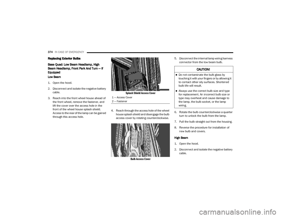
3. Reach into the front wheel house ahead of the front wheel, remove the fastener, and
lift the cover over the access hole in the
front of the wheel house splash shield.
Access to the rear of the lamp can be gained
through this access hole.
Splash Shield Access Cover
4. Reach through the access hole of the wheel house splash shield and disengage the bulb
access cover by rotating counterclockwise.
Bulb Access Cover
5. Disconnect the internal lamp wiring harness
connector from the low beam bulb.
6. Rotate the bulb counterclockwise a quarter turn to unlock the bulb from the lamp.
7. Pull the bulb straight out from the housing.
8. Reverse the procedure for installation of new bulb and covers.
High Beam
1. Open the hood.
2. Disconnect and isolate the negative battery cable.
1 — Access Cover
2 — Fastener
CAUTION!
Do not contaminate the bulb glass by
touching it with your fingers or by allowing it
to contact other oily surfaces. Shortened
bulb life will result.
Always use the correct bulb size and type
for replacement. An incorrect bulb size or
type may overheat and cause damage to
the lamp, the bulb socket, or the lamp
wiring.
20_DJD2_OM_EN_USC_t.book Page 374
Page 377 of 553
IN CASE OF EMERGENCY375
3. Look under the hood and behind the head -
lamp to find the high beam bulb access
cover.
4. Reach behind the headlamp and disengage the access cover by rotating counterclock -
wise.
5. Disconnect the internal lamp wiring harness connector from the high beam bulb.
6. Rotate the bulb counterclockwise a quarter turn to unlock the bulb from the lamp.
7. Pull the bulb straight out from the housing.
8. Reverse the procedure for installation of new bulb and covers. Front Park And Turn
1. Open the hood.
2. Disconnect and isolate the negative battery
cable.
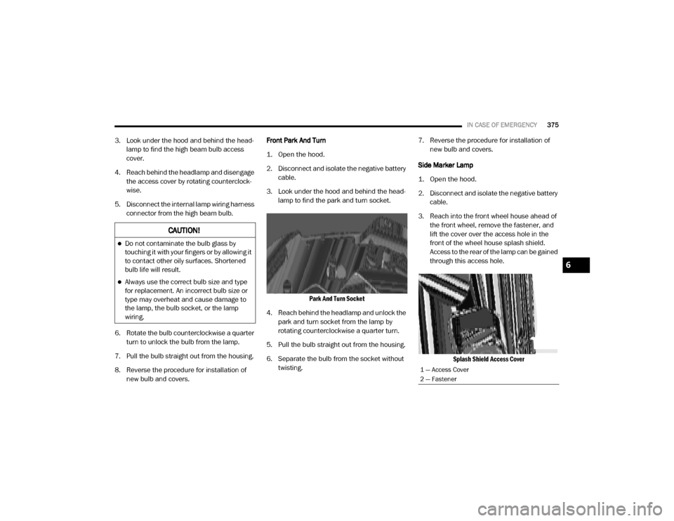
3. Look under the hood and behind the head -
lamp to find the park and turn socket.
Park And Turn Socket
4. Reach behind the headlamp and unlock the park and turn socket from the lamp by
rotating counterclockwise a quarter turn.
5. Pull the bulb straight out from the housing.
6. Separate the bulb from the socket without twisting. 7. Reverse the procedure for installation of
new bulb and covers.
Side Marker Lamp
1. Open the hood.
2. Disconnect and isolate the negative battery cable.
3. Reach into the front wheel house ahead of the front wheel, remove the fastener, and
lift the cover over the access hole in the
front of the wheel house splash shield.
Access to the rear of the lamp can be gained
through this access hole.
Splash Shield Access Cover
CAUTION!
Do not contaminate the bulb glass by
touching it with your fingers or by allowing it
to contact other oily surfaces. Shortened
bulb life will result.
Always use the correct bulb size and type
for replacement. An incorrect bulb size or
type may overheat and cause damage to
the lamp, the bulb socket, or the lamp
wiring.
1 — Access Cover
2 — Fastener
6
20_DJD2_OM_EN_USC_t.book Page 375
Page 432 of 553

430SERVICING AND MAINTENANCE
Tire Repair
If your tire becomes damaged, it may be
repaired if it meets the following criteria:
The tire has not been driven on when flat.
The damage is only on the tread section of
your tire (sidewall damage is not repairable).
The puncture is no greater than a ¼ of an
inch (6 mm).
Consult an authorized tire dealer for tire repairs
and additional information.
Damaged Run Flat tires, or Run Flat tires that
have experienced a loss of pressure should be
replaced immediately with another Run Flat tire
of identical size and service description (Load
Index and Speed Symbol). Replace the tire pres -
sure sensor as well as it is not designed to be
reused.
Run Flat Tires — If Equipped
Run Flat tires allow you the capability to drive
50 miles (80 km) at 50 mph (80 km/h) after a rapid loss of inflation pressure. This rapid loss
of inflation is referred to as the Run Flat mode.
A Run Flat mode occurs when the tire inflation
pressure is of/or below 14 psi (96 kPa). Once a
Run Flat tire reaches the run flat mode it has limited driving capabilities and needs to be
replaced immediately. A Run Flat tire is not
repairable. When a run flat tire is changed after
driving with underinflated tire condition, please
replace the TPM sensor as it is not designed to
be reused when driven under run flat mode 14
psi (96 kPa) condition.
NOTE:
TPM Sensor must be replaced after driving the
vehicle on a flat tire condition.
It is not recommended driving a vehicle loaded
at full capacity or to tow a trailer while a tire is in
the run flat mode.
See the tire pressure monitoring section for
more information.
Tire Spinning
When stuck in mud, sand, snow, or ice condi
-
tions, do not spin your vehicle's wheels above
30 mph (48 km/h) or for longer than 30
seconds continuously without stopping.
Refer to “Freeing A Stuck Vehicle” in “In Case Of
Emergency” for further information.
Tread Wear Indicators
Tread wear indicators are in the original equip -
ment tires to help you in determining when your
tires should be replaced.
Tire Tread
WARNING!
Fast spinning tires can be dangerous. Forces
generated by excessive wheel speeds may
cause tire damage or failure. A tire could
explode and injure someone. Do not spin your
vehicle's wheels faster than 30 mph (48 km/h)
for more than 30 seconds continuously when
you are stuck, and do not let anyone near a
spinning wheel, no matter what the speed.
1 — Worn Tire
2 — New Tire
20_DJD2_OM_EN_USC_t.book Page 430
Page 433 of 553

SERVICING AND MAINTENANCE431
These indicators are molded into the bottom of
the tread grooves. They will appear as bands
when the tread depth becomes a 1/16 of an
inch (1.6 mm). When the tread is worn to the
tread wear indicators, the tire should be
replaced.
Refer to “Replacement Tires” in this section for
further information.
Life Of Tire
The service life of a tire is dependent upon
varying factors including, but not limited to:
Driving style.
Tire pressure - Improper cold tire inflation
pressures can cause uneven wear patterns
to develop across the tire tread. These
abnormal wear patterns will reduce tread life,
resulting in the need for earlier tire replace -
ment.
Distance driven.
Performance tires, tires with a speed rating of
V or higher, and Summer tires typically have
a reduced tread life. Rotation of these tires
per the vehicle scheduled maintenance is
highly recommended. NOTE:
Wheel valve stem must be replaced as well
when installing new tires due to wear and tear
in existing tires.
Keep dismounted tires in a cool, dry place with
as little exposure to light as possible. Protect
tires from contact with oil, grease, and gasoline.
Replacement Tires
The tires on your new vehicle provide a balance
of many characteristics. They should be
inspected regularly for wear and correct cold
tire inflation pressures. The manufacturer
strongly recommends that you use tires equiva-
lent to the originals in size, quality and perfor
-
mance when replacement is needed. Refer to
the paragraph on “Tread Wear Indicators” in this section. Refer to the Tire and Loading Infor
-
mation placard or the Vehicle Certification Label
for the size designation of your tire. The Load
Index and Speed Symbol for your tire will be
found on the original equipment tire sidewall.
See the Tire Sizing Chart example found in the
“Tire Safety Information” section of this manual
for more information relating to the Load Index
and Speed Symbol of a tire.
It is recommended to replace the two front tires
or two rear tires as a pair. Replacing just one tire
can seriously affect your vehicle’s handling. If
you ever replace a wheel, make sure that the
wheel’s specifications match those of the orig -
inal wheels.
It is recommended you contact an authorized
tire dealer or original equipment dealer with any
questions you may have on tire specifications or
capability. Failure to use equivalent replace -
ment tires may adversely affect the safety,
handling, and ride of your vehicle.
WARNING!
Tires and the spare tire should be replaced
after six years, regardless of the remaining
tread. Failure to follow this warning can result
in sudden tire failure. You could lose control
and have a collision resulting in serious injury
or death.
7
20_DJD2_OM_EN_USC_t.book Page 431
Page 434 of 553
432SERVICING AND MAINTENANCE
Tire Types
All Season Tires — If Equipped
All Season tires provide traction for all seasons
(Spring, Summer, Autumn, and Winter). Traction
levels may vary between different all season
tires. All season tires can be identified by the
M+S, M&S, M/S or MS designation on the tire
sidewall. Use all season tires only in sets of four;
failure to do so may adversely affect the safety
and handling of your vehicle.
Summer Or Three Season Tires — If Equipped
Summer tires provide traction in both wet and
dry conditions, and are not intended to be
driven in snow or on ice. If your vehicle is
equipped with Summer tires, be aware these
tires are not designed for Winter or cold driving
conditions. Install Winter tires on your vehicle
when ambient temperatures are less than 40°F
(5°C) or if roads are covered with ice or snow. For more information, contact an authorized
dealer.
Summer tires do not contain the all season
designation or mountain/snowflake symbol on
the tire sidewall. Use Summer tires only in sets
of four; failure to do so may adversely affect the
safety and handling of your vehicle.
Snow Tires
Some areas of the country require the use of
snow tires during the Winter. Snow tires can be
identified by a “mountain/snowflake” symbol
on the tire sidewall.
If you need snow tires, select tires
equivalent in size and type to the orig -
inal equipment tires. Use snow tires
only in sets of four; failure to do so
may adversely affect the safety and handling of
your vehicle.
WARNING!
Do not use a tire, wheel size, load rating, or
speed rating other than that specified for
your vehicle. Some combinations of unap -
proved tires and wheels may change
suspension dimensions and performance
characteristics, resulting in changes to
steering, handling, and braking of your
vehicle. This can cause unpredictable
handling and stress to steering and
suspension components. You could lose
control and have a collision resulting in
serious injury or death. Use only the tire and
wheel sizes with load ratings approved for
your vehicle.
Never use a tire with a smaller load index or
capacity, other than what was originally
equipped on your vehicle. Using a tire with
a smaller load index could result in tire
overloading and failure. You could lose
control and have a collision.
Failure to equip your vehicle with tires
having adequate speed capability can
result in sudden tire failure and loss of
vehicle control.
CAUTION!
Replacing original tires with tires of a
different size may result in false speedometer
and odometer readings.
WARNING!
Do not use Summer tires in snow/ice
conditions. You could lose vehicle control,
resulting in severe injury or death. Driving too
fast for conditions also creates the possibility
of loss of vehicle control.
20_DJD2_OM_EN_USC_t.book Page 432