AUX Ram 2500 2020 Owner's Guide
[x] Cancel search | Manufacturer: RAM, Model Year: 2020, Model line: 2500, Model: Ram 2500 2020Pages: 553, PDF Size: 21.99 MB
Page 307 of 553
STARTING AND OPERATING305
Deactivation
The AUX Camera is deactivated by pressing the
“X” in the upper right corner of the touchscreen.
This will return the display back to the previ -
ously displayed screen.
NOTE:
If the AUX button is pressed and no AUX
Camera is connected, the touchscreen will
display a blue screen along with the message
“Camera System Unavailable.” The screen
can be exited out by pressing the “X” in the
upper right hand corner. This will return the
display back to the previously displayed
screen.
Zoom View is not available with the AUX
Camera feature.
The display will always default to the Trailer
Camera display (AUX 1).
SURROUND VIEW CAMERA SYSTEM — IF
EQUIPPED
Your vehicle may be equipped with the
Surround View Camera System that allows you
to see an on-screen image of the surroundings
and top view of your vehicle whenever the gear selector is put into REVERSE or manually acti
-
vated via the Uconnect system. The top view of
the vehicle will show which doors are open. The
image will be displayed on the touchscreen
display along with a caution note “Check Entire
Surroundings” across the top of the screen.
After five seconds, this note will disappear. The
Surround View Camera System is comprised of
four sequential cameras located in the front
grille, rear tailgate and side mirrors.
NOTE:
The Surround View Camera System has
programmable settings that may be selected
through the Uconnect System. Refer to “Ucon -
nect Settings” in “Multimedia” for further infor -
mation.
When the vehicle is shifted into REVERSE, the
rear camera view and top view is the default
view of the system (Automatic Activation).
When the vehicle is shifted out of REVERSE
(with camera delay turned on), the camera
image will continue to be displayed for up to 10
seconds after shifting out of REVERSE unless
the vehicle speed exceeds 8 mph (13 km/h),
the vehicle is shifted into PARK or the ignition is
placed in the OFF position. There is a touch -screen button “X” to disable the display of the
camera image.
When the vehicle is shifted out of REVERSE
(with camera delay turned off), the surround
view camera mode is exited and the last known
screen appears again.
While the “Rear View” camera is displayed and
guidelines are enabled, active guidelines are
overlaid on the image to illustrate the width of
the vehicle, including the side view mirrors and
its projected backup path based on the steering
wheel position.
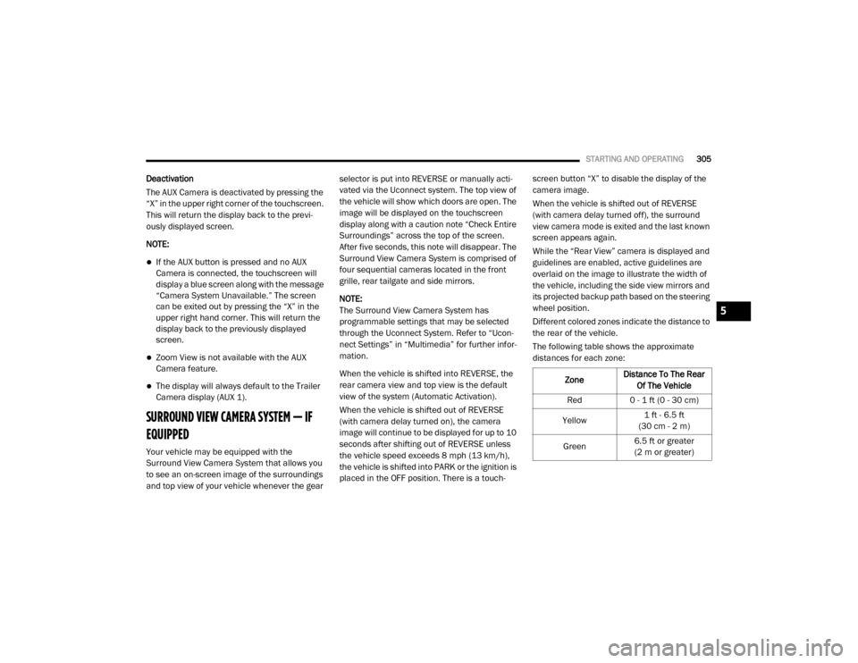
Different colored zones indicate the distance to
the rear of the vehicle.
The following table shows the approximate
distances for each zone:
Zone Distance To The Rear
Of The Vehicle
Red 0 - 1 ft (0 - 30 cm)
Yellow 1 ft - 6.5 ft
(30 cm - 2 m)
Green 6.5 ft or greater
(2 m or greater)
5
20_DJD2_OM_EN_USC_t.book Page 305
Page 313 of 553
STARTING AND OPERATING311
NOTE:
If the vehicle is not equipped with a Pickup Box:
The bottom wedge of the Top view will be
displayed in black.
The Rear Cross Path soft button will be
grayed out.
The guidelines will not be overlaid on Top
view/Rear view and Full Screen of Backup
Camera view.
Black video will be displayed for the right side
of the Top and Rear view, and full screen of
the Backup Camera view when the Rear View
Camera is not connected.
AUX Camera — If Equipped
Your vehicle may be equipped with one or two
AUX Cameras, which display rearview and side
view images from the trailer on the touch-
screen. Activation
The AUX Camera is activated by first pressing
the Backup Camera, Cargo Camera (if
equipped), or Surround View Camera (if
equipped) button on the touchscreen, followed
by the AUX button located in the upper left
corner of the rearview display. The AUX camera
can also be activated when the vehicle is in
REVERSE by pressing the AUX button.
If equipped with two AUX Cameras, you can
switch between each camera by then pressing
the AUX1 or AUX2 buttons on the Trailer Camera
display.
AUX1 Camera Button
AUX2 Camera Button Deactivation
The AUX Camera is deactivated by pressing the
“X” in the upper right corner of the touchscreen.
This will return the display back to the previ
-
ously displayed screen.
NOTE:
If the AUX button is pressed and no AUX
Camera is connected, the touchscreen will
display a blue screen along with the message
“Camera System Unavailable.” The screen
can be exited out by pressing the “X” in the
upper right hand corner. This will return the
display back to the previously displayed
screen.
Zoom View is not available with the AUX
Camera feature.
The display will always default to the Trailer
Camera display (AUX 1).
5
20_DJD2_OM_EN_USC_t.book Page 311
Page 344 of 553

342IN CASE OF EMERGENCY
(Continued)
NOTE:
Your vehicle may be transmitting data as
authorized by the subscriber.
Never place anything on or near the vehicle’s
LTE (voice/data) or 4G (data) and GPS
antennas. You could prevent LTE (voice/
data) or 4G (data) and GPS signal reception,
which can prevent your vehicle from placing
an emergency call. An operable LTE (voice/
data) or 4G (data) network connection and a
GPS signal is required for the SOS Call
system to function properly.
General Information
The following regulatory statement applies to all
Radio Frequency (RF) devices equipped in this
vehicle:
This device complies with Part 15 of the FCC
Rules and with Innovation, Science and
Economic Development Canada license-exempt
RSS standard(s). Operation is subject to the
following two conditions:
1. This device may not cause harmful interfer
-
ence, and
2. This device must accept any interference received, including interference that may
cause undesired operation.
Le présent appareil est conforme aux CNR
d`Innovation, Science and Economic Develop -
ment applicables aux appareils radio exempts
de licence. L'exploitation est autorisée aux deux
conditions suivantes:
1. l'appareil ne doit pas produire de brouil -
lage, et
2. l'utilisateur de l'appareil doit accepter tout brouillage radioélectrique subi, même si le
brouillage est susceptible d'en comprom -
ettre le fonctionnement.
La operación de este equipo está sujeta a las
siguientes dos condiciones:
1. es posible que este equipo o dispositivo no cause interferencia perjudicial y
2. este equipo o dispositivo debe aceptar cual -
quier interferencia, incluyendo la que
pueda causar su operación no deseada. NOTE:
Changes or modifications not expressly
approved by the party responsible for compli
-
ance could void the user’s authority to operate
the equipment.
JACKING AND TIRE CHANGING
WARNING!
Do not attempt to change a tire on the side
of the vehicle close to moving traffic. Pull
far enough off the road to avoid the danger
of being hit when operating the jack or
changing the wheel.
Being under a jacked-up vehicle is
dangerous. The vehicle could slip off the
jack and fall on you. You could be crushed.
Never put any part of your body under a
vehicle that is on a jack. If you need to get
under a raised vehicle, take it to a service
center where it can be raised on a lift.
Never start or run the engine while the
vehicle is on a jack.
20_DJD2_OM_EN_USC_t.book Page 342
Page 356 of 553
354IN CASE OF EMERGENCY
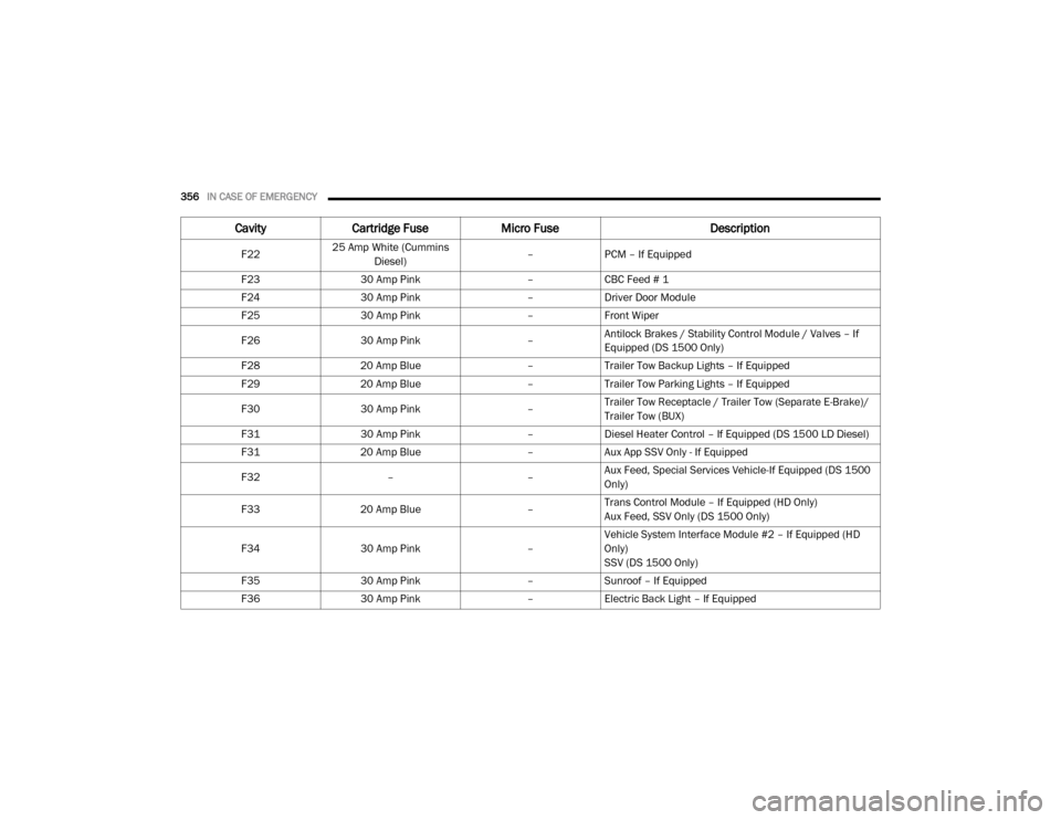
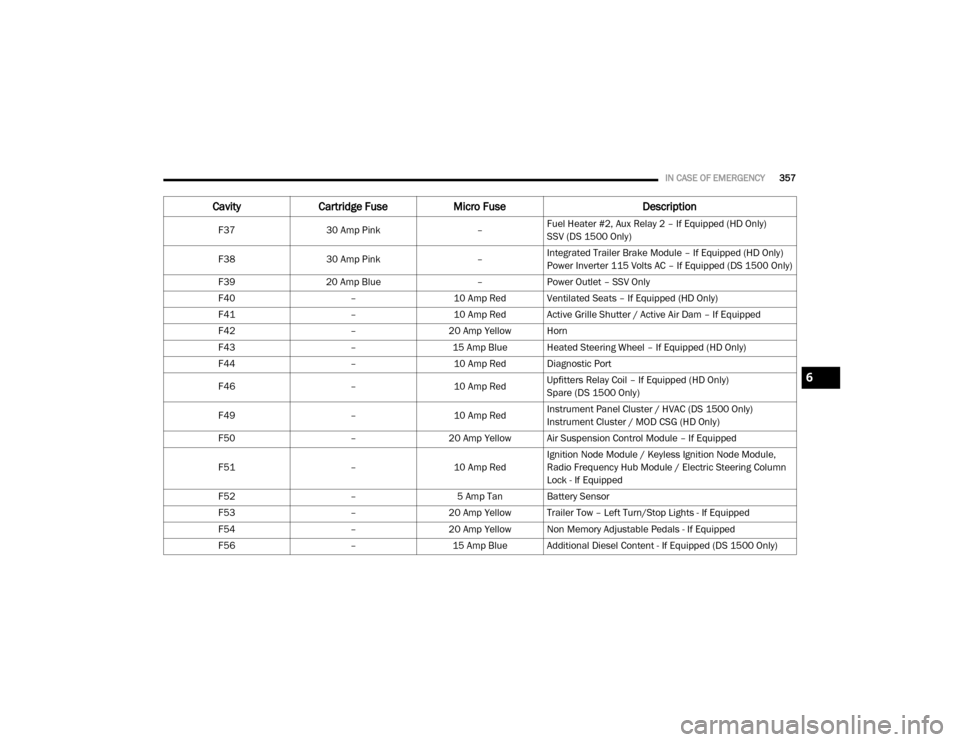
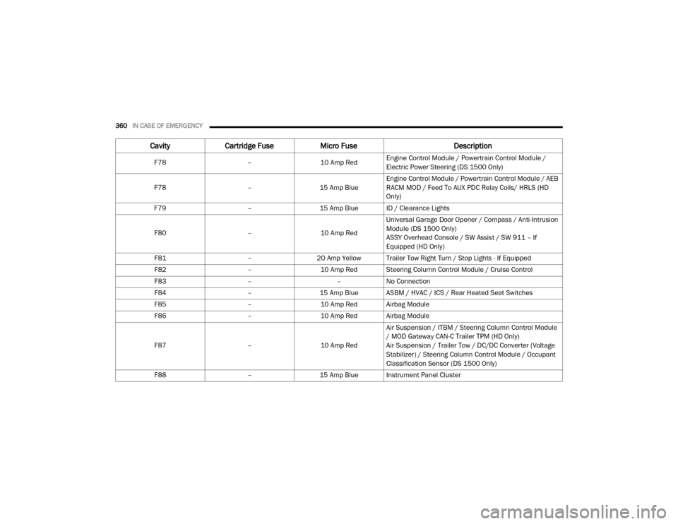
Power Distribution Center
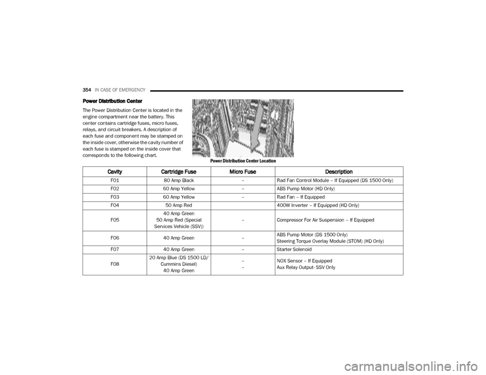
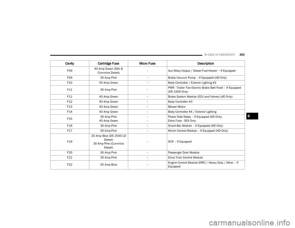
The Power Distribution Center is located in the
engine compartment near the battery. This
center contains cartridge fuses, micro fuses,
relays, and circuit breakers. A description of
each fuse and component may be stamped on
the inside cover, otherwise the cavity number of
each fuse is stamped on the inside cover that
corresponds to the following chart.
Power Distribution Center Location
CavityCartridge Fuse Micro Fuse Description
F0180 Amp Black –Rad Fan Control Module – If Equipped (DS 1500 Only)
F02 60 Amp Yellow –ABS Pump Motor (HD Only)
F03 60 Amp Yellow –Rad Fan – If Equipped
F04 50 Amp Red 400W Inverter – If Equipped (HD Only)
F05 40 Amp Green
50 Amp Red (Special
Services Vehicle (SSV)) –
Compressor For Air Suspension – If Equipped
F06 40 Amp Green –ABS Pump Motor (DS 1500 Only)
Steering Torque Overlay Module (STOM) (HD Only)
F07 40 Amp Green –Starter Solenoid
F08 20 Amp Blue (DS 1500 LD/
Cummins Diesel)40 Amp Green –
–
NOX Sensor – If Equipped
Aux Relay Output- SSV Only
20_DJD2_OM_EN_USC_t.book Page 354
Page 357 of 553
IN CASE OF EMERGENCY355
F0940 Amp Green (SSV &
Cummins Diesel) –
Aux Relay Output / Diesel Fuel Heater – If Equipped
F09 30 Amp Pink –Brake Vacuum Pump – If Equipped (HD Only)
F10 40 Amp Green –Body Controller / Exterior Lighting #2
F11 30 Amp Pink –PWR - Trailer Tow Electric Brake Batt Feed – If Equipped
(DS 1500 Only)
F11 40 Amp Green –Brake System Module (ECU and Valves) (HD Only)
F12 40 Amp Green –Body Controller #3
F13 40 Amp Green –Blower Motor
F14 40 Amp Green –Body Controller #4 / Exterior Lighting
F15 30 Amp Pink
40 Amp Green –
–Power Side Steps – If Equipped (HD Only)
Extra Fuse - SSV Only
F16 30 Amp Pink –Smart-Bar Module – If Equipped (HD Only)
F17 30 Amp Pink –Winch Control Module – If Equipped (HD Only)
F19 20 Amp Blue (DS 1500 LD
Diesel)
30 Amp Pink (Cummins Diesel) –
SCR – If Equipped
F20 30 Amp Pink –Passenger Door Module
F21 30 Amp Pink –Drive Train Control Module
F22 20 Amp Blue –Engine Control Module GPEC / Heavy Duty / Other – If
Equipped
Cavity
Cartridge Fuse Micro Fuse Description
6
20_DJD2_OM_EN_USC_t.book Page 355
Page 358 of 553
356IN CASE OF EMERGENCY
F2225 Amp White (Cummins
Diesel) –
PCM – If Equipped
F23 30 Amp Pink –CBC Feed # 1
F24 30 Amp Pink –Driver Door Module
F25 30 Amp Pink –Front Wiper
F26 30 Amp Pink –Antilock Brakes / Stability Control Module / Valves – If
Equipped (DS 1500 Only)
F28 20 Amp Blue –Trailer Tow Backup Lights – If Equipped
F29 20 Amp Blue –Trailer Tow Parking Lights – If Equipped
F30 30 Amp Pink –Trailer Tow Receptacle / Trailer Tow (Separate E-Brake)/
Trailer Tow (BUX)
F31 30 Amp Pink –Diesel Heater Control – If Equipped (DS 1500 LD Diesel)
F31 20 Amp Blue –Aux App SSV Only - If Equipped
F32 ––Aux Feed, Special Services Vehicle-If Equipped (DS 1500
Only)
F33 20 Amp Blue –Trans Control Module – If Equipped (HD Only)
Aux Feed, SSV Only (DS 1500 Only)
F34 30 Amp Pink –Vehicle System Interface Module #2 – If Equipped (HD
Only)
SSV (DS 1500 Only)
F35 30 Amp Pink –Sunroof – If Equipped
F36 30 Amp Pink –Electric Back Light – If Equipped
Cavity Cartridge Fuse Micro Fuse Description
20_DJD2_OM_EN_USC_t.book Page 356
Page 359 of 553
IN CASE OF EMERGENCY357
F3730 Amp Pink –Fuel Heater #2, Aux Relay 2 – If Equipped (HD Only)
SSV (DS 1500 Only)
F38 30 Amp Pink –Integrated Trailer Brake Module – If Equipped (HD Only)
Power Inverter 115 Volts AC – If Equipped (DS 1500 Only)
F39 20 Amp Blue –Power Outlet – SSV Only
F40 –10 Amp Red Ventilated Seats – If Equipped (HD Only)
F41 –10 Amp Red Active Grille Shutter / Active Air Dam – If Equipped
F42 –20 Amp Yellow Horn
F43 –15 Amp Blue Heated Steering Wheel – If Equipped (HD Only)
F44 –10 Amp Red Diagnostic Port
F46 –10 Amp RedUpfitters Relay Coil – If Equipped (HD Only)
Spare (DS 1500 Only)
F49 –10 Amp RedInstrument Panel Cluster / HVAC (DS 1500 Only)
Instrument Cluster / MOD CSG (HD Only)
F50 –20 Amp Yellow Air Suspension Control Module – If Equipped
F51 –10 Amp RedIgnition Node Module / Keyless Ignition Node Module,
Radio Frequency Hub Module / Electric Steering Column
Lock - If Equipped
F52 –5 Amp Tan Battery Sensor
F53 –20 Amp Yellow Trailer Tow – Left Turn/Stop Lights - If Equipped
F54 –20 Amp Yellow Non Memory Adjustable Pedals - If Equipped
F56 –15 Amp Blue Additional Diesel Content - If Equipped (DS 1500 Only)
CavityCartridge Fuse Micro Fuse Description
6
20_DJD2_OM_EN_USC_t.book Page 357
Page 362 of 553
360IN CASE OF EMERGENCY
F78 –10 Amp RedEngine Control Module / Powertrain Control Module /
Electric Power Steering (DS 1500 Only)
F78 –15 Amp BlueEngine Control Module / Powertrain Control Module / AEB
RACM MOD / Feed To AUX PDC Relay Coils/ HRLS (HD
Only)
F79 –15 Amp Blue ID / Clearance Lights
F80 –10 Amp RedUniversal Garage Door Opener / Compass / Anti-Intrusion
Module (DS 1500 Only)
ASSY Overhead Console / SW Assist / SW 911 – If
Equipped (HD Only)
F81 –20 Amp Yellow Trailer Tow Right Turn / Stop Lights - If Equipped
F82 –10 Amp Red Steering Column Control Module / Cruise Control
F83 ––No Connection
F84 –15 Amp Blue ASBM / HVAC / ICS / Rear Heated Seat Switches
F85 –10 Amp Red Airbag Module
F86 –10 Amp Red Airbag Module
F87 –10 Amp RedAir Suspension / ITBM / Steering Column Control Module
/ MOD Gateway CAN-C Trailer TPM (HD Only)
Air Suspension / Trailer Tow / DC/DC Converter (Voltage
Stabilizer) / Steering Column Control Module / Occupant
Classification Sensor (DS 1500 Only)
F88 –15 Amp Blue Instrument Panel Cluster
CavityCartridge Fuse Micro Fuse Description
20_DJD2_OM_EN_USC_t.book Page 360
Page 472 of 553

470MULTIMEDIA
Audio
After pressing the Audio button on the touchscreen, the following settings will be available:
Setting Name Selectable Options
Balance/FadeFrontBack LeftRight
NOTE:
The “Balance/Fade” feature allows you to adjust the Balance and Fade settings. Press and drag the Speaker icon or use the arrows to adjust, tap the
C icon to readjust to the center. Equalizer + –
NOTE:
When in the “Equalizer” display you may adjust the Bass, Mid and Treble settings. Speed Adjusted Volume Off123
NOTE:
The “Speed Adjusted Volume” feature increases or decreases volume relative to vehicle speed. Surround Sound — If Equipped On
Off
NOTE:
The “Surround Sound” feature provides simulated surround sound mode. AUX Volume Offset — If Equipped On
Off
NOTE:
The “AUX Volume Offset” feature provides the ability to tune the audio level for portable devices connected through the AUX input. Loudness — If Equipped On Off
NOTE:
The “Loudness” feature improves sound quality at lower volumes.
20_DJD2_OM_EN_USC_t.book Page 470
Page 490 of 553
488MULTIMEDIA
NOTE:
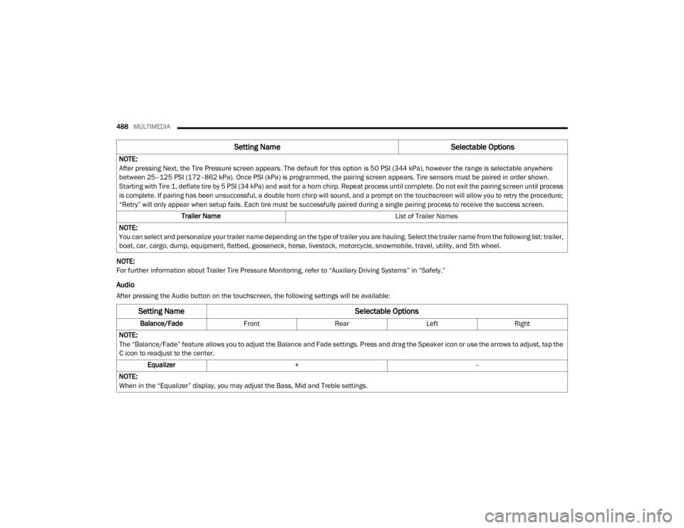
For further information about Trailer Tire Pressure Monitoring, refer to “Auxiliary Driving Systems” in “Safety.”
Audio
After pressing the Audio button on the touchscreen, the following settings will be available:NOTE:
After pressing Next, the Tire Pressure screen appears. The default for this option is 50 PSI (344 kPa), however the range is selectable anywhere
between 25–125 PSI (172–862 kPa). Once PSI (kPa) is programmed, the pairing screen appears. Tire sensors must be paired in order shown.
Starting with Tire 1, deflate tire by 5 PSI (34 kPa) and wait for a horn chirp. Repeat process until complete. Do not exit the pairing screen until process
is complete. If pairing has been unsuccessful, a double horn chirp will sound, and a prompt on the touchscreen will allow you to retry the procedure;
“Retry” will only appear when setup fails. Each tire must be successfully paired during a single pairing process to receive the success screen.
Trailer Name List of Trailer Names
NOTE:
You can select and personalize your trailer name depending on the type of trailer you are hauling. Select the trailer name from the following list: trailer,
boat, car, cargo, dump, equipment, flatbed, gooseneck, horse, livestock, motorcycle, snowmobile, travel, utility, and 5th wheel.
Setting Name Selectable Options
Setting NameSelectable Options
Balance/Fade Front Rear LeftRight
NOTE:
The “Balance/Fade” feature allows you to adjust the Balance and Fade settings. Press and drag the Speaker icon or use the arrows to adjust, tap the
C icon to readjust to the center. Equalizer + –
NOTE:
When in the “Equalizer” display, you may adjust the Bass, Mid and Treble settings.
20_DJD2_OM_EN_USC_t.book Page 488